Videotec NTL Benutzerhandbuch
- Kategorie
- Überwachungskamera-Zubehör
- Typ
- Benutzerhandbuch

1
Bedienungsanweisung
Manuel d’instruction
Operating instructions
Manuale istruzioni
Grande custodia in acciaio Inox per telecamere termiche
Large stainless steel thermal cameras housing
Grand caisson en acier Inox pour caméras thermiques
Große Gehäuse aus rostfreiem Stahl für Wärmebildkameras
Крупный кожух из нержавеющей стали для тепловых
телекамер

2
NORME DI SICUREZZA 3
DESCRIZIONE 3
Prodotti ed accessori 3
Pulizia del vetro IR 3
INSTALLAZIONE 3
Apertura della custodia 3
Installazione della telecamera 3
Installazione della custodia 4
Installazione ricambio vetro al germanio 4
Limiti di utilizzo 4
SPECIFICHE TECNICHE 5
Custodia 5
Riscaldamento 5
Supporti 5
Certificazioni 5
INDICE
ITALIANO Custodia per grandi ottiche
SAFETY RULES 6
INTRODUCTION 6
Product and accessories 6
Cleaning IR glass 6
INSTALLATION 6
How to open the housing 6
How to install the camera 6
Installing the housing 7
Changing the germanium glass 7
Limits to use 7
TECHNICAL SPECIFICATIONS 8
Housing 8
Heater 8
Brackets 8
Certifications 8
INDEX
ENGLISH Housing for big lenses
NORMES DE SECURITÉ 9
DESCRIPTION 9
Produits et accessoires 9
Nettoyage de la vitre IR 9
INSTALLATION 9
Ouverture du caisson 9
Installation de la camera 9
Installation du caisson 10
Installation vitre au germanium de remplacement 10
Limites d’utilisation 10
SPÉCIFICATIONS TECHNIQUES 11
Caisson 11
Chauffage 11
Supports 11
Certifications 11
ПРАВИЛА ТЕХНИКИ БЕЗОПАСНОСТИ 15
ОПИСАНИЕ 15
15
15
УСТАНОВКА 15
15
15
16
. 16
16
ТЕХНИЧЕСКАЯ СПЕЦИФИКАЦИЯ 17
17
17
17
INDEX
FRANCAIS
РУССКИЙ
Caisson pour grandes optiques
Предохранительный кожух для больших объективов
SICHEREITSNORMEN 12
BESCHREIBUNG 12
Produkte und zubehör 12
Reinigung der IR-Scheibe 12
INSTALLATION 12
Öffnung des Schutzgehauses 12
Installation der Kamera 12
Installation des Gehaüse 13
Einbau des Germanium-Austauschglases 13
Anwendungsbereiche 13
TECHNISCHE DATEN 14
Gehäuse 14
Heizung 14
Halterungen 14
Zertifizierungen 14
INHALTSVERZEICHNIS
DEUTSCH Gehäuse für große Optiken

3
Custodia antivandalismo per telecamera ed accessori
ITALIANO
NORME DI SICUREZZA
• Collegare ad una linea di alimentazione
corrispondente a quella indicata sulle etichette
di marcatura.
• La presa di alimentazione deve essere connessa
adeguatamente a terra secondo le norme
vigenti.
• Prima di spostare o effettuare interventi
tecnici sull’apparecchio, isolarlo e scollegarlo
dall’alimentazione.
• Non utilizzare cavi di tensione con segni di usura
o invecchiamento, in quanto rappresentano un
grave pericolo per l’incolumità degli utilizzatori.
• L’installazione dell’apparecchio (e dell’intero
impianto di cui esso fa parte) deve essere
effettuata da personale tecnico adeguatamente
qualificato.
• Non utilizzare l’apparecchio in presenza di
sostanze infiammabili.
• Accertarsi che l’apparecchio sia fissato in
maniera solida utilizzando fissaggi adeguati per
il peso e la superficie di montaggio.
• L’apparecchio si considera disattivato soltanto
quando l’alimentazione é isolata e i cavi di
collegamento con altri dispositivi sono stati
scollegati dall’alimentazione.
• Conservare con cura il presente manuale per
ogni futura consultazione.
DESCRIZIONE
Custodia ermetica per telecamere CCD, interamente
costruita in acciaio inox, chiusa da 2 flange di grosso
spessore. La flangia posteriore permette il passaggio
dei cavi mediante 4 pressacavi PG13,5. Costruita
in acciaio inox AISI 316, é particolarmente indicata
per ambienti marini o industriali dove gli agenti
atmosferici sono altamente aggressivi.
h
Le operazioni di installazione elettrica
devono essere eseguite solo da
personale qualificato secondo le normative
vigenti. Prima di eseguire qualsiasi operazione
assicurarsi che sia tolta l’alimentazione elettrica.
Prodotti ed accessori
- Tettuccio parasole
- Tergicristallo + pompa lavavetri
- Riscaldamento 1 PTC
- Alimentatore per telecamera
Pulizia del vetro IR
Si consigliano saponi neutri diluiti con acqua.
h
Pulire la finestra con il filtro IR prestando
attenzione a non graffiare o rigare la
superficie esterna trattata con carbon coating.
Danneggiando tale rivestimento c’è il rischio
di compromettere la trasparenza all’infrarosso
della superficie. Sono da evitare alcool etilico,
solventi, idrocarburi idrogenati, acidi forti e
alcali. L’utilizzo di detti prodotti danneggia in
modo irreparabile la superficie del vetro IR e
delle parti in plastica.
INSTALLAZIONE
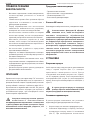
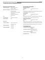
Apertura della custodia
Per l’apertura della custodia svitare le viti poste
sul fondo posteriore (Fig. 1) utilizzando la chiave
esagonale in dotazione. Si può accedere all’interno
della custodia sia dalla flangia posteriore che da
quella anteriore. Una volta aperta la custodia
togliere il fermo (Fig. 2, punto 2) e sfilare la slitta
interna utilizzando l’apposita feritoia di presa (Fig. 2,
punto 3).
h
Nel caso si acceda alla custodia dalla
flangia anteriore prestare particolare
attenzione al PTC di riscaldamento (indicazioni
riportate su etichette presenti).
Installazione della telecamera
Questa sezione descrive come installare la
telecamera all’interno della custodia.
1. Aprire la custodia come precedentemente
descritto.
2. Montare la telecamera sulla slitta utilizzando la
piastrina isolante e la vite da 1/4” in dotazione (Fig. 3).
Se necessario utilizzare i distanziali per posizionare

ITALIANO
Custodia antivandalismo per telecamera ed accessori
4
nel modo corretto telecamera ed ottica.
3. Inserire i cavi attraverso i pressacavi ed eseguire
le connessioni elettriche necessarie, assicurarsi
che i pressacavi siano fissati saldamente.
Versione 12V DC/24V AC: Il circuito risulterà
connesso tramite i morsetti indicati nello
schema in Fig. 4 nel caso di tensione di
alimentazione del riscaldamento di 24V AC.
Versione 115/230V AC: Il circuito risulterà
connesso tramite i morsetti indicati nello
schema in Fig. 5 nel caso di tensione
di alimentazione del riscaldamento di
115/230V AC.
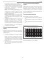
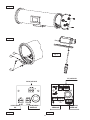
4. Fissare la flangia anteriore completa di vetro al
germanio, e flangia posteriore completa dei 4
pressacavi, al corpo custodia tramite le apposite
viti di fissaggio (Fig.6). Prestare attenzione a non
danneggiare le guarnizioni di tenuta (assicurarsi
che siano correttamente inserite nelle proprie
sedi).
Installazione della custodia
Questa sezione descrive come installare la custodia
su staffa a parete o su brandeggio.
1. Montaggio tettuccio parasole: interporre fra il
tettuccio e le flange della custodia i distanziali
cilindrici in dotazione. Fissare quindi il tettuccio
sulla custodia con le viti in dotazione, in
corrispondenza dei distanziali (Fig. 7)
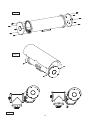
2. Montare la custodia sulla staffa a parete (Fig. 9)
oppure sulla staffa del brandeggio (Fig. 8).
Installazione ricambio vetro al
germanio
Il vetro al germanio presenta due colorazioni.
All’interno della custodia grazie ad uno strato
anti riflesso assume una colorazione variabile
(in funzione dell’orientamento). All’esterno
è presente invece uno strato anti-graffio il
quale conferisce una colorazione grigio scuro.
Per installare il ricambio fare riferimento alla
Fig. 6.
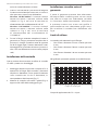
Limiti di utilizzo
La custodia può montare 3 tipi di flangia:
• Con finestra diametro 55 mm e vetro spessore
2 mm
• Con finestra diametro 70 mm e vetro spessore
2 mm
• Con finestra diametro 110 mm e vetro spessore
3 mm
Nel grafico è riportato lo spettro visivo della finestra.
0
10
20
30
40
50
60
70
80
90
100
2,5
3
4
5
6
7
8
9
10
11
12
13
14
Ge AR 2 lati - Spessore 2mm
Lunghezza d’onda (µm)
Trasmittanza (%)
Campo di applicazione da 7.5 a 14 µm.

5
Custodia antivandalismo per telecamera ed accessori
ITALIANO
SPECIFICHE TECNICHE
Custodia
-Dimensioni esterne:
228x211x720 mm / 9x8.3x28.3 in
(con tettuccio)
-Dimensioni interne:
116x116x562 mm / 4.5x4.5x22.1 in
(lunghezza massima)
116x116x477 mm / 4.5x4.5x18.7 in
(con circuito, Fig. 4)
116x116x473 mm / 4.5x4.5x18.6 in
(con circuito, Fig. 5)
-Peso:
13 Kg
-Materiale:
Acciaio inossidabile AISI 316
-Grado di protezione:
IP67
Riscaldamento
-Alimentazione:
12V DC/24V AC, 20 W
110-240V AC, 40 W
-Temperatura ON:
< 15°C ± 3°C
< 59°F ± 5°F
-Temperatura OFF:
> 22°C ± 3°C
> 72°F ± 5°F
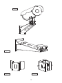
Supporti
Staffa a parete
-Dimensioni:
140x185x597 mm / 5.5x7.3x23.5 in
-Peso:
5,5 Kg
Fissaggio a parete: lo snodo consente la regolazione su due assi, portata
55 Kg. Vedi Fig. 10.
Adattatore angolare
-Dimensioni:
295x180x165 mm / 11.6x7.1x6.5 in
-Peso:
2,3 Kg
Questo adattatore permette, assieme alla staffa, il fissaggio ad angolo
della custodia. Portata 50 Kg. Vedi Fig. 11.
Adattatore a palo
-Dimensioni:
190x174x100 mm / 7.5x6.9x4 in
-Peso:
2,5 Kg
Questo adattatore permette, assieme alla staffa, il fissaggio a palo della
custodia. Dimensioni del palo comprese tra Ø 110 e Ø 150 mm. Portata
50 Kg. Vedi Fig. 12.
Certificazioni
-Sicurezza elettrica (CE):
EN60065
-Compatibilità elettromagnetica (CE):
EN50130-4, EN61000-6-3
-Grado di protezione IP:
EN60529 (IP66/IP67)
-Certificazione EAC

6
ENGLISH
Vandal resistant camera housing and accessories
SAFETY RULES
• Connect the unit to a power supply corresponding
to the one indicated on the rating.
• The outlet must be adequately earthed
according to the regulations in force.
• Before moving or carrying out technical
operations on the unit, isolate and disconnect it
from the power supply.
• Do not use worn or damaged power cords, since
they represent a serious risk for the user’s safety.
• The installation of the unit (and the associated
equipment of which the unit is part) must be
carried out by adequately skilled technical
personnel.
• Do not use the device in areas containing
inflammable substances.
• Make sure that the unit is mounted securely
using fixings adequate for the weight and the
mounting surface.
• The unit is considered switched off only when
the power supply is isolated and the connecting
cables to the unit are disconnected from the
supply.
• Keep this manual safe for future reference.
INTRODUCTION
Weatherproof housing for CCD camera, entirely
constructed of stainless steel, enclosed by 2 heavy
duty flanges. The back flange allows the cables to
run though 4 PG13,5 cable glands. Made of AISI 316
stainless steel, it is particularly designed for marine
and industrial environments where the external
agents are highly corrosive.
h
The electrical installation operations
must only be carried out by qualified
personnel, according to the laws and regulations
in force. Turn off the power before performing
any operation.
Product and accessories
- Sunshield
- Wiper and washer
- Heater 1 PTC
- Camera power supply
Cleaning IR glass
We recommend using neutral soap diluted in water.
h
When cleaning the window with the IR
filter, take extra care not to scratch or
damage the outer surface treated with carbon
coating. Damage to this coating could also
interfere with the transparency of the surface to
infrared light. Do not use ethyl alcohol, solvents,
hydrogenated hydrocarbons, strong acids or
alkalis. These products will irreparably damage
the surface of the IR glass and the plastic parts.
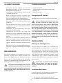
INSTALLATION
How to open the housing
To open the housing unscrew the bolts on the
bottom flange (Fig. 1) using the hexagonal spanner
supplied. The access into the housing can be both
from the back flange and from the front one. When
the housing is opened remove the slide block (Fig. 2,
point 2) and slip off the inner slide using the relevant
fixing slit (Fig. 2, point 3).
h
Opening the housing from the frontal
flange pay attention to the PTC heating
(see the marks shown on the labels).
How to install the camera
This chapter described how to install the camera
into the housing.
1. Open the housing as described previously.
2. Fit the camera on the slide, using the insulating
plate and the supplied 1/4” screw (Fig. 3).
If necessary, use the spacers to position the
camera and optics correctly.
3. Feed the cables through the cable grip, and make
the necessary electrical connections, ensuring that
the cable grips are holding firmly.
Version 12V DC/24V AC: When the power supply
voltage is 24V AC the circuit will be connected by
the terminals shown in the diagram in Fig. 4.
Version 115/230V AC: When the power supply
voltage is 115/230V AC the circuit will be
connected by the terminals shown in the diagram
in Fig. 5.

7
Vandal resistant camera housing and accessories
ENGLISH
4. Fix the frontal flange, complete with the
germanium glass, and the back flange, complete
with the 4 cable glands, to the housing body
using the supplied fixing screws (Fig.6). Pay
attention not to damage the sealing rings (be
sure they are properly inserted in their seats).
Installing the housing
This section describes how to install the housing on
the wall bracket or on the Pan & Tilt head.
1. Sunshield assembly: between the sunshield
and the flanges of the housing, position the
spacers supplied. Then, fasten the sunshield
to the housing with the screws supplied,
corresponding to the spacers (Fig. 7).
2. Mount the housing on the wall bracket (Fig. 9) or
on the Pan & Tilt head bracket (Fig. 8).
Changing the germanium glass
Germanium glass has two colours. Inside the
housing there is an anti-reflection coating that
changes colour (depending on the direction of
vision). On the outside, on the other hand, there
is a scratchproof coating to make the glass dark
grey in colour. To install the new glass see
Fig. 6.
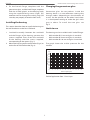
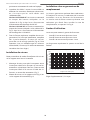
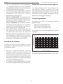
Limits to use
The housing can be installed with 3 kind of flange:
• With window Ø 55 mm and glass 2 mm thick
• With window Ø 70 mm and glass 2 mm thick
• With window Ø 110 mm and glass 3 mm thick
The graph shows the visible spectrum for the
window.
0
10
20
30
40
50
60
70
80
90
100
2,5
3
4
5
6
7
8
9
10
11
12
13
14
Ge AR 2 sides - 2mm Thick
Wavelength (µm)
Transmittance (%)
Field of application from 7.5 to 14 µm.

8
ENGLISH
Vandal resistant camera housing and accessories
TECHNICAL SPECIFICATIONS
Housing
-External dimensions:
228x211x720 mm / 9x8.3x28.3 in
(with sunshield)
-Internal dimensions:
116x116x562 mm / 4.5x4.5x22.1 in
(max. lenght)
116x116x477 mm / 4.5x4.5x18.7 in
(with circuit, Fig. 4)
116x116x473 mm / 4.5x4.5x18.6 in
(with circuit, Fig. 5)
-Weight:
13 Kg
-Material:
Stainless steel AISI 316
-Weatherproof:
IP67
Heater
-Power supply:
12V DC/24V AC, 20 W
110-240V AC, 40 W
-Temperature ON:
< 15°C ± 3°C
< 59°F ± 5°F
-Temperature OFF:
> 22°C ± 3°C
> 72°F ± 5°F
Brackets
Wall bracket
-Dimensions:
140x185x597 mm / 5.5x7.3x23.5 in
-Weight:
5,5 Kg
Wall mount, two degrees of freedom, load rating 55 Kg. See Fig. 10.
Angled adapter
-Dimensions:
295x180x165 mm / 11.6x7.1x6.5 in
-Weight:
2,3 Kg
This adapter, along with the bracket, allows you to fix the housing at an
angle. Load rating 50 kg. See Fig. 11.
Pole adapter
-Dimensions:
190x174x100 mm / 7.5x6.9x4 in
-Weight:
2,5 Kg
This adapter, along with the bracket, allows you to fix the housing onto
a pole. The size of the pole can be between Ø 110 and Ø 150 mm in
diameter. Load rating: 50 kg. See Fig. 12.
Certifications
-Electrical safety (CE):
EN60065
-Electromagnetic compatibility (CE):
EN50130-4, EN61000-6-3
-IP protection degree:
EN60529 (IP66/IP67)
-EAC certification

9
Caisson antivandalisme pour camera video et accessoires
FRANÇAIS
NORMES DE SECURITÉ
• Raccorder à un feeder suivant les indications
des plaques des caractéristiques.
• La prise d’alimentation doit être raccordée
à la terre conformément aux normes en
vigueur.
• Avant de déplacer ou effectuer des
interventions techniques sur l’appareil,
l’isoler et le débrancher de l’alimentation.
• Ne pas employer de câbles de tension avec
signes d’usure ou vieillissement, parce qu’ils
peuvent compromettre sérieusement la
sécurité des utilisateurs.
• L’installation de l’appareil (et du système
complet dont il fait partie) doit être
effectuée par une personne qualifiée du
point de vue téchnique.
• Ne pas employer l’appareil en présence de
substances inflammables.
• Vérifier si l’appareil est fixé de façon solide
en utilsant les fixages appropriés pour le
poids et la surface de montage.
• L’appareil est désactivé seulement quand
l’alimentation est isolée et les câbles de
raccordement avec d’autres dispositifs ont
été enlevés de l’alimentation.
• Conserver soigneusement ce manuel pour
toute consultation future.
DESCRIPTION
Caisson de protection étanche pour caméra CCD,
entièrement construite en acier inox, fermé avec
2 brides de grosse épaisseur. La bride arrière
permet le passage des câbles au moyen de 4
serre-câbles PG13,5. Construit en accier Inox
AISI 316, il est particulièrement indiqué pour
ambiances marines ou industrielles où les agents
externes sont trés agressifs.
h
Les opérations d’installation
électrique doivent être effectuées
uniquement par du personnel qualifié
conformément aux normes en vigueur.
Avant d’effectuer toute opération, il est
indispensable de couper l’alimentation.
Produits et accessoires
- Toit pare-soleil
- Essuie glace et lave glace
- Chauffage 1 PTC
- Alimentation pour caméra
Nettoyage de la vitre IR
Il est conseillé d’utiliser un savon neutre dilué à l’eau.
h
Nettoyer la fenêtre avec filtre IR en
ayant soin de ne pas rayer ni érafler
l’enduit protecteur de carbone externe.
L’endommagement du revêtement risque de
compromettre la transparence à l’infrarouge
de la surface. Éviter toute utilisation d’alcool
éthylique, de solvants, d’hydrocarbures
hydrogénés, d’acides forts et d’alcalis.
L’utilisation de ce type de produit endommagera
irrémédiablement la surface de la vitre IR et des
parties en plastique.
INSTALLATION
Ouverture du caisson
Pour ouvrir le caisson dévisser les vis placées sur le
fond arrière (Fig. 1) en utilisant la clef hexagonale
fournie. On peut ouvrir soit la bride arrière que
la bride antérieure. Aprés l’ouverture du caisson,
remuer l’arrêtoir (Fig. 2, point 2) et enlever la glissière
interne en utilisant la fente d’accrochage (Fig. 2,
point 3).
h
Dans le cas où on va ouvrir le caisson par
la bride antérieure faire attention au PTC
du chauffage (informations indiquées dans les
etiquettes presentes).
Installation de la camera
Cette section explique comment installer la caméra à
l’interieur du caisson.
1. Ouvrir le caisson en suivant les descriptions
précédentes.
2. Monter la caméra sur la glissière en utilisant la
plaque isolante et la vis de 1/4’’ fournie en dotation
(Fig. 3). Utiliser s’il le faut les entretoises pour

10
FRANÇAIS
Caisson antivandalisme pour camera video et accessoires
positionner correctement la caméra et l’optique.
3. Introduire les câbles à travers le serre-câbles et
effectuer les conexions électriques nécessaires,
en s’assurant que les serre-câbles sont
solidement fixés.
Version 12V DC/24V AC: Le circuit est connecté
au moyen des bornes indiquées sur le
schéma de la Fig. 4 dans le cas d'une tension
d'alimentation de chauffage de 24V AC.
Version 115/230V AC: Le circuit est connecté au
moyen des bornes indiquées sur le schéma de la
Fig. 5 dans le cas d'une tension d'alimentation
de chauffage de 115/230V AC.
4. Fixer la flasque antérieure, complète du vitre au
germanium, et la flasque postérieure, complète
des 4 presse-étoupes, au corps du caisson
parmi des vis de serrage spéciaux (Fig. 6). Faire
attention à ne pas endommager les anneaux
d’étanchéité (s’assurer qu’ils soient correctement
introduits dans leur sièges).
Installation du caisson
Cette partie décrit le mode d’installation du caisson
sur le support mural ou sur la tourelle.
1. Montage du toit pare-soleil: interposez entre
le toit pare-soleil et les flasques du caisson les
entretoises cylindriques fournies. Fixez ensuite
le toit pare-soleil sur le caisson à l’aide des vis
fournies, au niveau des entretoises (Fig. 7).
2. Monter le caisson sur le support mural (Fig. 9) ou
sur le support de la tourelle (Fig. 8).
Installation vitre au germanium de
remplacement
La vitre au germanium présente deux colorations.
À l’intérieur du caisson, la coloration de la couche
antireflets varie en fonction de l’orientation.
La couche anti-éraflures externe présente une
coloration gris foncé. Pour installer la vitre de
remplacement, se reporter à la Fig. 6.
Limites d’utilisation
Le caisson peut monter 3 genres de face avant:
• Avec Ø 55 mm et verre épaisseur 2 mm
• Avec Ø 70 mm et verre épaisseur 2 mm
• Avec Ø 110 mm et verre épaisseur 3 mm
Le diagramme représente le spectre visuel de la
fenêtre.
0
10
20
30
40
50
60
70
80
90
100
2,5
3
4
5
6
7
8
9
10
11
12
13
14
Ge AR 2 côtés - Épaisseur 2mm
Longueur d’onde (µm)
Transmittance (%)
Plage d’application de 7,5 à 14 µm.

11
Caisson antivandalisme pour camera video et accessoires
FRANÇAIS
SPÉCIFICATIONS TECHNIQUES
Caisson
-Surface extérieure:
228x211x720 mm / 9x8.3x28.3 in
(avec toit pare-soleil)
-Surface intérieure:
116x116x562 mm / 4.5x4.5x22.1 in
(longueur max.)
116x116x477 mm / 4.5x4.5x18.7 in
(avec circuit, Fig. 4)
116x116x473 mm / 4.5x4.5x18.6 in
(avec circuit, Fig. 5)
-Poids:
13 Kg
-Matériau:
Acier inoxydable AISI 316
-Degré d’étanchéité:
IP67
Chauffage
-Alimentation:
12V DC/24V AC, 20 W
110-240V AC, 40 W
-Température ON:
< 15°C ± 3°C
< 59°F ± 5°F
-Température OFF:
> 22°C ± 3°C
> 72°F ± 5°F
Supports
Support mural
-Dimentionnement:
140x185x597 mm / 5.5x7.3x23.5 in
-Poids:
5,5 Kg
Support mural: deux degrés de liberté, charge utile 55 Kg. Voir Fig. 10.
Adaptateur angulaire
-Dimensionnement:
295x180x165 mm / 11.6x7.1x6.5 in
-Poids:
2,3 Kg
Cet adaptateur permet, avec l’étrier, de fixer le caisson à angle. Charge
utile: 50 kg. Voir Fig. 11.
Adaptateur sur support à tige
-Dimentionnement:
190x174x100 mm / 7.5x6.9x4 in
-Poids:
2,5 Kg
Cet adaptateur permet, avec l’étrier, de fixer le caisson sur un support à
tige. Les dimensions de la tige varient entre Ø 110 et Ø 150 mm. Charge
utile: 50 kg. Voir Fig. 12.
Certifications
-Sécurité électrique (CE):
EN60065
-Compatibilité électromagnétique (CE):
EN50130-4, EN61000-6-3
-Degré de protection IP:
EN60529 (IP66/IP67)
-Certification EAC

12
DEUTSCH
Antivandalismus Kameragehäuse und Zubehör
SICHEREITSNORMEN
• Schließen Sie die Einheit an eine der
Betriebseigenschaften auf den Datenschildern
entsprechende Stromquelle an.
• Gemäß dem in Kraft befindlichen Gesetz muss die
Steckdose geerdet sein.
• Bevor Sie die Einrichtung verstellen oder
technische Eingriffe vornehmen, stellen Sie sicher,
dass das System isoliert und ausgeschaltet ist.
• Keine beschädigten oder verschlissenen Netzkabel
benutzen, weil sie die Sicherheit der Benutzer
gefährden.
• Die Installation des Geräts (und der ganzen
Anlage) muss nur von qualifiziertem Personal
ausgeführt werden.
• Vermeiden Sie die Arbeitszone, die leicht
entzündbare Stoffe enthalten.
• Vergewissern Sie sich, dass das Gerät stabil
befestigt ist und dass geeignete Halterungen für
die Einsatzoberfläche und für das Gewicht benutzt
werden.
• Das Gerät wird deaktiviert gehalten, wenn die
Strom versorgung isoliert und ausgeschaltet ist
und die Verbindungskabel, die das Gerät mit
anderen Einheiten verbinden, entfernt worden
sind.
• Bewahren Sie das vorliegende Bedienungs-
handbuch sorgfältig für zukunftiges Nachschlagen
auf.
BESCHREIBUNG
Wasserfestes Gehäuse für CCD-Kamera aus AISI 316
Edelstahl, umgeben von 2 dicken Flanschen. Der
hintere Flansch gestattet den Durchlauf der Kabel
durch 4 PG13,5 Kabelschellen. Es ist besonders
geeignet für Seegebiete oder Industriebetriebe wo die
Witterungsein-flüsse seher aggressiv sind.
h
Die elektrische Installation darf nur vom
qualifizierten Personal unter Beachtung
der geltenden Normen durchgeführt werden.Vor
allen Eingriffen immer den Netzstecker aus der
Steckdose ziehen!
Produkte und zubehör
- Sonnen Schutzdach
- Scheibenwischer und Scheibenwascherpumpe
- Heizung 1 PTC
- Netzteil für Kamera
Reinigung der IR-Scheibe
Empfohlen wird eine in Wasser verdünnte Neutralseife.
h
Bei der Reinigung des Fensters mit dem
IR-Filter ist darauf zu achten, dass die
mit Carbon Coating behandelte Oberfläche
nicht verkratzt oder gerillt wird. Wenn diese
Beschichtung Schaden nimmt, besteht die Gefahr,
dass die Durchlässigkeit der Oberfläche für
Infrarotstrahlen beeinträchtigt wird. Zu vermeiden
sind Äthylalkohol, Lösungsmittel, hydrierte
Kohlenwasserstoffe, starke Säuren und Alkalien.
Durch diese Produkte wird die Oberfläche der
IR-Glasscheibe und der Kunststoffteile irreparabel
geschädigt.
INSTALLATION
Öffnung des Schutzgehauses
Um das Gehäuse zu öffnen, die Schrauben am
hinteren Boden ausdrehen (Fig. 1), indem man
den mitgelieferten Sechskantschlüssel verwendet.
Der Zugriff kann an Innere des Gehäuses sowohl
vom Vorderflansch als auch vom Hinterflansch
sein. Wenn das Gehäuse geöffnet worden ist, die
Schlittensperre (Fig. 2, Punkt 2) abnehem und den
internen Schlitten durch den Schlitz (Fig. 2, Punkt 3)
herausziehen.
h
Wenn man das Gehäuse vom vorderen
Flansch öffnet, muss man auf der PTC-
Heizung aufmerksam sein (siehe die Hinweis-
etikette).
Installation der Kamera
In diesem Abschnitt wird beschrieben, wie die Kamera
im Inneren des Schutzgehäuses installiert wird.
1. Das Gehäuse wie zuvor beschrieben öffnen.
2. Die Kamera auf den Schlitten positionieren, indem

13
Antivandalismus Kameragehäuse und Zubehör
DEUTSCH
man das Isolierplättchen und die mitgelieferte
1/4“ Schraube benutzt (Fig. 3). Falls erforderlich
Abstandstücke benutzen, um die Fernsehkamera
unddie Optik korrekt zu positionieren.
3. Die Kabel durch die Kabelschellen einführen
und die notwendigen elektrischen Anschlüsse
durchführen; sich vergewissern, daß die
Kabelschellen gut befestigt sind.
Version 12V DC/24V AC: Die Schaltung wird,
wenn die Heizung mit einer Spannung von 24V AC
versorgt wird, mit den Klemmen angeschlossen,
die im Schema der Fig. 4 dargestellt sind.
Version 115/230V AC: Die Schaltung wird, wenn
die Heizung mit einer Spannung von 115/230V AC
versorgt wird, mit den Klemmen angeschlossen,
die im Schema der Fig. 5 dargestellt sind.
4. Den vorderen Flansch mit Germanium Glass und
den rückseitigen Flansch mit 4 Kabelschellen
zusammen mit dem Körper des Gehäuses
befestigen. Benützen den Befestigungsschrauben,
die ausgestatten werden (Fig. 6). Versichern
sich die Dichtungen nicht zu beschädigen, (die
Dichtungen in die richtigen Sitze einreihen).
Installation des Gehaüse
In diesem Abschnitt wird beschrieben, wie man
das Gehaüse auf der Wandhalterung oder auf dem
Schwenkkopf installiert.
1.
Montage Sonnenschutzdach: zwischen
Sonnenschutzdach und den Flanschen des
Gehäuses die im Lieferumfang enthaltenen
zylindrischen Abstandsstücke einlegen. Dann
das Sonnenschutzdach am Gehäuse mit den im
Lieferumfang enthaltenen Schrauben entsprechend
der Abstandsstücke befestigen (Fig. 7).
2. Das Gehaüse auf der Wandhalterung (Fig. 9) oder
auf der Schwenkkopf-Halterung (Fig. 8) montieren.
Einbau des Germanium-Austauschglases
Das Germaniumglas weist zwei Farbtöne auf.
Innerhalb des Gehäuses verändert sich wegen
einer reflexmindernden Schicht die Farbe mit der
Ausrichtung. Auf der Außenseite ist es wegen der
kratzfesten Schicht hingegen dunkelgrau. Für den
Einbau des Austauschglases siehe Fig. 6.
Anwendungsbereiche
Das Gehäuse kann mit 3 verschiedenen Flansche
geliefert werden:
• Mit Ø 55 mm und Glasdicke 2 mm
• Mit Ø 70 mm und Glasdicke 2 mm
• Mit Ø 110 mm und Glasdicke 3 mm
In der Grafik ist das sichtbare Spektrum des Fensters
dargestellt.
0
10
20
30
40
50
60
70
80
90
100
2,5
3
4
5
6
7
8
9
10
11
12
13
14
Ge AR 2 Seiten - 2mm- Dicke
Wellenlänge (µm)
Transmission (%)
Der Anwendungsbereich liegt zwischen 7.5 und 14 µm.

14
DEUTSCH
Antivandalismus Kameragehäuse und Zubehör
TECHNISCHE DATEN
Gehäuse
-Ausmaße:
228x211x720 mm / 9x8.3x28.3 in
(mit Sonnenschutzdach)
-Innenmaße:
116x116x562 mm / 4.5x4.5x22.1 in
(max. Länge)
116x116x477 mm / 4.5x4.5x18.7 in
(mit Kreis, Fig. 4)
116x116x473 mm / 4.5x4.5x18.6 in
(mit Kreis, Fig. 5)
-Gewicht:
13 Kg
-Material:
Rostfreier Stahl AISI 316
-Schutzart:
IP67
Heizung
-Ausmaße:
12V DC/24V AC, 20 W
110-240V AC, 40 W
-Temperatur ON:
< 15°C ± 3°C
< 59°F ± 5°F
-Temperatur OFF:
> 22°C ± 3°C
> 72°F ± 5°F
Halterungen
Wandhalterung
-Ausmaße:
140x185x597 mm / 5.5x7.3x23.5 in
-Gewicht:
5,5 Kg
Wandhalterung, Max.Tragkraft kk Kg. Siehe Fig. 10.
Eckadapter
-Ausmaße:
295x180x165 mm / 11.6x7.1x6.5 in
-Gewicht:
2,3 Kg
Dieser Adapter gestattet zusammen mit dem Bügel die Eckbefestigung
des Gehäuses. Max.Tragkraft 50 kg. Siehe Fig. 11.
Pfahladapter
-Ausmaße:
190x174x100 mm / 7.5x6.9x4 in
-Gewicht:
2,5 Kg
Dieser Adapter gestattet zusammen mit dem Bügel die
Pfahlbefestigung des Gehäuses. Abmessungen des Pfahls zwischen Ø
110 und Ø 150 mm. Max.Tragkraft 50 kg. Siehe Fig. 12.
Zertifizierungen
-Elektrische Sicherheit (CE):
EN60065
-Elektromagnetische Verträglichkeit (CE):
EN50130-4, EN61000-6-3
-Schutzart IP:
EN60529 (IP66/IP67)
-EAC-Zertifizierung

15
Вандалозащищенный кожух для камеры и аксессуаров
РУССКИЙ
ПРАВИЛА ТЕХНИКИ
БЕЗОПАСНОСТИ
• ,
.
•
.
•
,
.
•
,
.
• (
, )
.
•
.
• ,
,
.
• ,
,
,
.
•
.
ОПИСАНИЕ
2
.
4 PG13.5.
AISI 316,
,
.
h
Операции электроустановки должны
выполняться исключительно
квалифицированным персоналом и в соответствии
с действующими местными правилами. Перед
выполнением любой операции убедиться, что
источники питания отсечены.
Продукция и комплектующие
-
- - +
- 1 PTC
-
Очистка ИК стекла
, .
h
Очистите окно с фильтром IR, обращая
внимание на то, чтобы не поцарапать
внешнюю поверхность, обработанную
графитовым покрытием. При повреждении этой
поверхности, существует риск негативно повлиять
на инфракрасную прозрачность поверхности.
Избегать применение этилового спирта,
растворителей, гидрированных углеводородов,
сильных кислот и щелочей. Использование
названных продуктов наносит непоправимый
вред поверхности ИК стекла и пластмассовым
поверхностям.
УСТАНОВКА
Открытие корпуса
, ,
(. 1)
.
,
. ,
(. 2, 2)
, (. 2,
3).
h
В случае доступа к кожуху из переднего
фланца, обратить особое внимание на ПТК
нагрева (инструкции на имеющихся этикетках).
Установка видеокамеры
,
.
1. , .
2. ,
1/4
(. 3).

16
РУССКИЙ
Вандалозащищенный кожух для камеры и аксессуаров
.
3.
,
.
Версия 12 В пост.т./24 В пер.т.:
,
. 4
24 ..
Версия 115/230 В пер.т.:
, . 5
115/230
..
4.
, 4
(.6).
,
(,
).
Установка предохранительного
кожуха
,
.
1. :
.
,
(. 7).
2.
(. 9)
(. 8).
Установка запасного германиевого
окошка.
2 .
( ).
,
- .
. . 6.
Эксплуатационные пределы
3 :
• 55 2
• 70 2
• 110 3
.
0
10
20
30
40
50
60
70
80
90
100
2,5
3
4
5
6
7
8
9
10
11
12
13
14
Ge AR 2 стороны - Толщина 2мм
Длина волны (µm)
Переходная проводимость (%)
7,5 14 .

17
РУССКИЙ
Вандалозащищенный кожух для камеры и аксессуаров
ТЕХНИЧЕСКАЯ СПЕЦИФИКАЦИЯ
Предохранительный кожух
-Внешние габариты: 228x211x720 мм / 9x8.3x28.3 в
(с проивос. панелью)
-Внутренние габариты
: 116x116x562 мм / 4.5x4.5x22.1 в
(максимальная длина)
116x116x477 мм / 4.5x4.5x18.7 дюймов
(с контуром, Рис. 4)
116x116x473 мм / 4.5x4.5x18.6 в
(с контуром, Рис. 5)
-Вес: 13 кг
-Тип материала: Нержавеющая сталь AISI 316
-Класс защиты: IP67
Нагреватель
-Система питания: 12 В пост.т./24 В пер.т., 20 Вт
110-240 В пер.т., 40 Вт
-Температура ВКЛ: < 15°C ± 3°C
< 59°F ± 5°F
-Температура ВЫКЛ: > 22°C ± 3°C
> 72°F ± 5°F
Кронштейны крепления
Настенный кронштейн
-Размеры: 140x185x597 мм / 5.5x7.3x23.5 в
-Вес: 5,5 кг
Настенный монтаж: соединение позволяет выполнять регулировку в двух осях
свободы, несущая способность 55 кг. См. рис. 10.
Угловой адаптер
-Размеры: 295x180x165 мм / 11.6x7.1x6.5 в
-Вес: 2,3 кг
Данный адаптер позволяет вместе с кронштейном выполнять угловой монтаж
предохрнительного кожуха. Несущая способность 50 кг. См. рис. 11.
Адаптер с опорным шестом
-Размеры: 190x174x100 мм / 7.5x6.9x4 в
-Вес: 2,5 кг
Данный адаптер позволяет вместе с кронштейном выполнять монтаж с
опорным шестом предохранительного кожуха. Опорный шест имеет размеры
включительно между Ø 110 и Ø 150 мм. Несущая способность 50 кг. См. рис. 12.
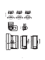
Сертификация
-Электрическая безопасность (CE):
EN60065
-Электромагнитная совместимость (CE):
EN50130-4, EN61000-6-3
-Степень защиты IP корпуса:
EN60529 (IP66/IP67)
-Сертификат EAC

18
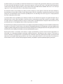
12V DC/24V AC
HEATER OUT
12V DC/24V AC
OUT
12V DC/24V AC IN
115/230V AC IN
115/230V AC
HEATER OUT
115/230V AC
CAMERA OUT
1
2
3
Fig. 5Fig. 4
Fig. 3
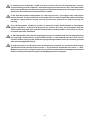
Fig. 2
Fig. 1

19
Fig. 8
Fig. 7
Fig. 6

20
Fig. 10
Fig. 11 Fig. 12
Fig. 9
Seite wird geladen ...
Seite wird geladen ...
Seite wird geladen ...
Seite wird geladen ...
-
 1
1
-
 2
2
-
 3
3
-
 4
4
-
 5
5
-
 6
6
-
 7
7
-
 8
8
-
 9
9
-
 10
10
-
 11
11
-
 12
12
-
 13
13
-
 14
14
-
 15
15
-
 16
16
-
 17
17
-
 18
18
-
 19
19
-
 20
20
-
 21
21
-
 22
22
-
 23
23
-
 24
24


Videotec NTL Benutzerhandbuch
- Kategorie
- Überwachungskamera-Zubehör
- Typ
- Benutzerhandbuch
in anderen Sprachen
- français: Videotec NTL Manuel utilisateur
- italiano: Videotec NTL Manuale utente
Verwandte Artikel
-
Videotec NTL Benutzerhandbuch
-
-
-
-
-
-
-
-
-