Mitsubishi SEZ-KD25VAL Bedienungsanleitung
- Kategorie
- Split-System-Klimaanlagen
- Typ
- Bedienungsanleitung
Dieses Handbuch eignet sich auch für

INSTALLATION MANUAL
For safe and correct use, please read this installation manual thoroughly before installing the air-conditioner
unit.
INSTALLATIONSHANDBUCH
Zum sicheren und ordnungsgemäßen Gebrauch der Klimaanlage das Installationshandbuch gründlich
durchlesen.
MANUEL D’INSTALLATION
Veuillez lire le manuel d’installation en entier avant d’installer ce climatiseur pour éviter tout accident et vous
assurer d’une utilisation correcte.
E°XEIPI¢IO O¢H°IøN E°KATA™TA™H™
°È· ·ÛÊ¿ÏÂÈ· Î·È ÛˆÛÙ‹ ¯Ú‹ÛË, ·Ú·Î·Ï›ÛÙ ‰È·‚¿ÛÂÙ ÚÔÛ¯ÙÈο ·˘Ùfi ÙÔ ÂÁ¯ÂÈÚ›‰ÈÔ ÂÁηٿÛÙ·Û˘
ÚÈÓ ·Ú¯›ÛÂÙ ÙËÓ ÂÁηٿÛÙ·ÛË Ù˘ ÌÔÓ¿‰·˜ ÎÏÈÌ·ÙÈÛÌÔ‡.
MANUAL DE INSTALACIÓN
Para un uso seguro y correcto, lea detalladamente este manual de instalación antes de montar la unidad de
aire acondicionado.
INSTALLATIEHANDLEIDING
Voor een veilig en juist gebruik moet u deze installatiehandleiding grondig doorlezen voordat u de airconditioner
installeert.
MANUALE DI INSTALLAZIONE
Per un uso sicuro e corretto, leggere attentamente questo manuale di installazione prima di installare il condizionatore
d’aria.
INSTALLATIONSMANUAL
Läs denna installationsmanual noga för säkert och korrekt bruk innan luftkonditioneringen installeras.
INSTALLATIONSMANUAL
Læs venligst denne installationsmanual grundigt, før De installerer airconditionanlægget, af hensyn til sikker og
korrekt anvendelse.
MANUAL DE INSTALAÇÃO
Para segurança e utilização correctas, leia atentamente este manual de instalação antes de instalar a unidade
de ar condicionado.
РУКОВОДСТВО ПО УСТАНОВКЕ
Для осторожного и правильного использования прибора необходимо тщательно ознакомиться с данным
руководством по установке до выполнения установки кондиционера.
MONTAJ ELK‹TABI
Emniyetli ve do¤ru biçimde nas›l kullan›laca¤›n› ö¤renmek için lütfen klima cihaz›n› monte etmeden önce bu
elkitab›n› dikkatle okuyunuz.
FOR INSTALLER
FÜR INSTALLATEURE
POUR L’INSTALLATEUR
°π∞ ∞À∆√¡ ¶√À ∫∞¡∂π ∆∏¡ ∂°∫∞∆∞™∆∞™∏
PARA EL INSTALADOR
VOOR DE INSTALLATEUR
PER L’INSTALLATORE
TIL INSTALLATØREN
PARA O INSTALADOR
FÖR INSTALLATÖREN
ДЛЯ УСТАНОВИТЕЛЯ
MONTÖR ‹Ç‹N
English
Deutsch
Français
Español
Italiano
Nederlands
Svenska
Dansk
Português
∂ÏÏËÓÈο
Русский
Türkçe
Air-Conditioners
SEZ-KD25,KD35,KD50,KD60,KD71VAL
KB79H173H01_cv.p65 07.7.9, 2:12 PM1

2
3
[Fig. 3-1]
4
[Fig. 4-1]
B
A
A
C
D
C
E
D
A Unit body
B Lifting machine
C Nuts (field supply)
D Washers (accessory)
E M10 hanging bolt (field supply)
5
[Fig. 5-1] [Fig. 5-2] [Fig. 5-3]
YX
LW
A
Z
A Center of gravity
A Indoor unit’s bottom surface
A
D
C
A
B
[Fig. 3-2]
A 100 mm or more
B 350 mm or more
C Basically open 100 mm or more without only obstruction in front and on
both sides of the unit.
D 200 mm or more (Open two sides of left, right, or rear side.)
■ SUZ-KA25VA
3.1
5.2
5.1
3.3
B
C
D
A
F
G
3
4
E
A
50~150 450
450
49
625
777
20
100
90
23
C
B
A
D
B
E
200
1
2
A Access door
B Electrical parts box
C Air inlet
D Air outlet
E Ceiling surface
F Service space (viewed from the side)
G Service space (viewed from the direction of arrow)
1 600 mm or more
2 100 mm or more
3 10 mm or more
4 300 mm or more
Model
SEZ-KD25
SEZ-KD35, 50
SEZ-KD60, 71
A
700
900
1100
B
752
952
1152
C
798
998
1198
D
660
860
1060
E
800
1000
1200
(mm)
KB79H173H01_illust.p65 07.7.9, 2:12 PM2

3
6
[Fig. 6-1]
ØB
ØA
a
b
a Indoor unit
b Outdoor unit
a
d
cb
ef
90°
d
c
b
a
b
a
a
b
e
b
c
d
c
A
c
b
a
defgh
i
[Fig. 6-9]
A
B
C
D
F
G
E
M
L
E
F
L
AG
H
H
K
L
J
I
J
O
O
N
N
20
20
20
20
A
B 1
[Fig. 6-10]
[Fig. 6-3]
[Fig. 6-6]
[Fig. 6-4] [Fig. 6-5]
a Flare nut
b Copper tube
a Burr
b Copper tube/pipe
c Spare reamer
d Pipe cutter
[Fig. 6-7]
[Fig. 6-8]
C C C
D 2
E
A Downward slope 1/100 or more
B Connection dia. R1 external thread
C Indoor unit
D Collective piping
E Maximize this length to approx. 10 cm
a Flaring tool
b Die
c Copper tube
d Flare nut
e Yo k e
a Smooth all around
b Inside is shining without
any scratches
c Even length all around
d Too much
e Tilted
f Scratch on
flared plane
g Cracked
h Uneven
i Bad examples
6.1
6.2
a Copper tubes
b Good
c No good
d Tilted
e Uneven
f Burred
6.3
6.5
Model
SEZ-KD25, 35
SEZ-KD50
SEZ-KD60
SEZ-KD71
A
9.52
12.7
15.88
15.88
B
6.35
6.35
6.35
9.52
D
E
H
G
I
F
B
C
525
A
A Indoor unit
B Pipe cover (short) (accessory)
C Tie band (accessory)
D Band fixing part
E Insertion margin
F Drain hose (accessory)
G Drain pipe (O.D. ø32 PVC TUBE, field supply)
H Insulating material (field supply)
I Max.145 ± 5 mm
[Fig. 6-11]
A Pipe cover (small) (accessory)
B Caution:
Pull out the thermal insulation on the refrigerant piping at the
site, insert the flare nut to flare the end, and replace the insu-
lation in its original position.
Take care to ensure that condensation does not form on ex-
posed copper piping.
C Liquid end of refrigerant piping
D Gas end of refrigerant piping
E Site refrigerant piping
F Main body
G Pipe cover (large) (accessory)
H Thermal insulation (field supply)
I Pull
J Flare nut
K Return to original position
L Ensure that there is no gap here
M Plate on main body
N Band (accessory)
O Ensure that there is no gap here. Place join upwards.
KB79H173H01_illust.p65 07.7.9, 2:12 PM3

4
E
F
I
H
G
S3
S2
S1
S3
S2S1
CN90
L
J
K
A
B
A Indoor unit
B Outdoor unit
C Signal receiving unit
D Wireless remote controller
E Main switch/fuse
F Grounding
[Fig. 8-1]
[Fig. 8-2-1]
A
C
D
B
E
S3
S3
S2
S1
S2S1
For Power supply
For Power
supply
E Use PG bushing to keep the weight of the cable and external force from being
applied to the power supply terminal connector. Use a cable tie to secure the cable.
F Power source wiring
G Tensile force
H Use ordinary bushing
I Signal receiving unit wiring
J Terminal bed for power source and indoor transmission
K To 1-phase power source
L Connecting the signal receiving unit
Connect the signal receiving unit to the CN90 (Connect to the wireless remote
controller board) on the indoor unit using the supplied remote controller wire. Con-
nect the signal receiving units to all the indoor units.
A Terminal bed box
B Knockout hole
C Remove
A Screw holding cover (2pcs)
B Cover
[Fig. 8-2-3] [Fig. 8-2-4]
[Fig. 8-2-2]
F
G
E
DC
BA
[Fig. 7-1]
A Air inlet
B Air outlet
C Access door
D Ceiling surface
E Canvas duct
F Air filter
G Inlet grille
7
E
F
C C
B
A A
C
A
8.2
A
B
C
8
8.1
KB79H173H01_illust.p65 07.7.9, 2:13 PM4

5
A For installation in the switch box:
B For direct installation on the wall select one of the following:
• Prepare a hole through the wall to pass the remote controller cord (in order to run the remote controller cord from
the back), then seal the hole with putty.
• Run the remote controller cord through the cut-out upper case, then seal the cut-out notch with putty similarly as
above.
C Wall
D Conduit
E Lock nut
F Bushing
G Switch box
H Remote controller cord
I Seal with putty
F
A
H
C
D
E
G
I
I
I
H
B
B-1. B-2.
[Fig. 8-4]
8.3
[Fig. 8-3]
A Indoor terminal block
B Earth wire (green/yellow)
C Indoor/outdoor unit connecting wire 3-
core 1.5 mm
2
or more
D Outdoor terminal block
E Power supply cord : 2.0 mm
2
or more
F Indoor controller board
1 Connecting cable
Cable 3-core 1.5 mm
2
, in conformity
with Design 245 IEC 57.
2 Indoor terminal block
CN90
6
5
2
4
3
7
L
N
1
A Indoor terminal block
C Indoor/outdoor unit
connecting wire
3-core 1.5 mm
2
or
more
D Outdoor terminal block
B Earth wire (green/yellow)
E Power supply cord : 2.0 mm
2
or more
3 Outdoor terminal block
4 Always install an earth wire (1-core 1.5
mm
2
) longer than other cables
5 Signal receiving unit cable (accessory)
(wire length : 5 m)
6 Signal receiving unit
7 Power supply cord
Cable 3-core 2.0 mm
2
or more, in con-
formity with Design 245 IEC 57.
F Indoor controller
board
8
8.2
J41
J42
JP1
JP2
JP3
CN90 CN4F CN44 CN20(Red) CNMF
SW1 SW2
CN32
CN41CN51
ON OFF
SWE
CN2L
CN22(Blue)
CNP
(Blue)
CN3C(Blue)
CN01
(Black)
CN90: Connector for remote controller wire connection
Controller circuit board on the indoor unit (reference)
IC
OC(00)
CN90
TB1
TB4
1
D
C
A
B
Standard 1:1
[Fig. 8-5]
[Fig. 8-6]
IC IC IC IC
CN90 CN90 CN90 CN90
Pair number: 0
[Fig. 8-7]
IC
CN90
IC
CN90
IC IC IC IC
CN90 CN90 CN90 CN90
[Fig. 8-9][Fig. 8-8]
Pair number: 0 Pair number: 1 Pair number: 2 Pair number: 3
Pair number: 0 Pair number: 1 Pair number: 2 Pair number: 3
Pair number: 0 Pair number: 0 Pair number: 0 Pair number: 0
Pair number: 0 Pair number: 0
Pair number: 0
A Outdoor unit
B Refrigerant address
C Indoor unit
D Signal receiving unit
Indoor/outdoor wiring
Signal receiving unit wiring
KB79H173H01_illust.p65 07.7.9, 2:13 PM5

6
8
8.3
A
B
C
D
E
G
H
F
A Signal receiving unit external
B Center of Switch box
C Switch box
D Installation pitch
E 6.5 mm (1/4 inch)
F 70 mm (2 - 3/4 inch)
G 83.5 ± 0.4 mm (3 - 9/32 inch)
H Protrusion (pillar, etc)
[Fig. 8-11]
A
B
C
A Remote controller wire
B Hole (drill a hole on the ceiling to pass the remote controller wire.)
C Signal Receiving Unit
Ceiling cassette type, Ceiling concealed type
[Fig. 8-12]
A
B
C
A Fix tightly with tape.
B Remote controller wire
C Order wire
[Fig. 8-13]
A
Insert the minus screwdriver toward the
arrow pointed and wrench it to remove
the cover.
A flat screwdriver whose width of blade is
between 4 and 7 mm (5/32 - 9/32 inch)
must be used.
[Fig. 8-14]
1
1
2
A
Indoor unit
1 Hang the cover to the upper hooks (2 places).
2 Mount the cover to the lower case
A Cross-section of upper hooks
[Fig. 8-10]
[Fig. 8-15]
H
J
I
When using the switch box
When installing directly on the wall
A 150 mm (5 - 15/16 inch)
B Remote controller wire (Accessory)
C Wiring pipe
D Locknut
H Seal around here with putty
I Remote controller wire
J Seal around here with putty
E Bushing
F Switch box
G Seal around here with putty
C
D
B
F
E
G
A
Wall
KB79H173H01_illust.p65 07.7.9, 2:13 PM6

7
8
8.3
[Fig. 8-16]
[Fig. 8-17]
AB
C
D
A Thin-wall portion
B Bottom case
C Remote controller wire
D Conducting wire
[Fig. 8-18]
A
A Screw (M4 × 30)
* When installing the lower case directly on the wall or the ceiling,
use wood screws.
Insert the minus screwdriver toward the
arrow pointed and wrench it to remove the
cover.
A flat screwdriver whose width of blade is
between 4 and 7 mm (5/32 - 9/32 inch)
must be used.
[Fig. 8-19]
1
1
2
A
1 Hang the cover to the upper hooks (2 places).
2 Mount the cover to the lower case
A Cross-section of upper hooks
A Loosen terminal screw
B Terminal block
C Lead wire
B
C
A
[Fig.8-20] [Fig. 8-21]
Service panel
Remove one fixing
screw to open the
service panel.
Be sure to fix the
indoor/outdoor unit
connecting wire using
this cord clamp.
8.4
KB79H173H01_illust.p65 07.7.9, 2:13 PM7

8
3
12
CHECK CHECK
CHECKCHECK
4
ON/OFF TEMP
FAN
VANE
TEST RUN
AUTO STOP
AUTO START
h
min
LOUVER
MODE
CHECK
RESETSET CLOCK
CHECK
E
F
D
C
A
B
A Hour button
B Minute button
C TEMP button
D TEMP button
E ON/OFF button
F CHECK button
[Fig.8-22]
8.5
9
[Fig. 9-1]
A TEST RUN button
B MODE button
C FAN button
D VANE button
9.1
ON/OFF TEMP
FAN
VANE
TEST RUN
AUTO STOP
AUTO START
h
min
LOUVER
MODE
CHECK
RESETSET CLOCK
TEST RUN
B
A
C
D
10
[Fig. 10-1]
B
A
G
H
K
L
M
I
J
C
D
E
F
A Indoor unit
B Union
C Liquid pipe
D Gas pipe
E Stop valve
F Outdoor unit
G Refrigerant gas cylinder operating valve
H Refrigerant gas cylinder for R410A with
siphon
I Refrigerant (liquid)
J Electronic scale for refrigerant charging
K Charge hose (for R410A)
L Gauge manifold valve (for R410A)
M Service port
10.1
KB79H173H01_illust.p65 07.7.9, 2:13 PM8

9
Contents
1. Safety precautions
• Please report to or take consent by the supply authority before connection
to the system.
• Be sure to read “The following should always be observed for safety” before
installing the air conditioner.
• Be sure to observe the cautions specified here as they include important
items related to safety.
• The indications and meanings are as follows.
Warning:
Could lead to death, serious injury, etc.
Caution:
Could lead to serious injury in particular environments when operated incor-
rectly.
• After reading this manual, be sure to keep it together with the instruction
manual in a handy place on the customer’s site.
Symbols put on the unit
: Indicates an action that must be avoided.
: Indicates that important instructions must be followed.
: Indicates a part which must be grounded.
: Indicates that caution should be taken with rotating parts.
: Indicates that the main switch must be turned off before servicing.
: Beware of electric shock.
: Beware of hot surface.
Warning:
Carefully read the labels affixed to the main unit.
Warning:
• Do not install it by yourself (customer).
Incomplete installation could cause injury due to fire, electric shock, the unit
falling or leakage of water. Consult the dealer from whom you purchased the
unit or special installer.
• Install the unit securely in a place which can bear the weight of the unit.
When installed in an insufficient strong place, the unit could fall causing in-
jured.
• Use the specified wires to connect the indoor and outdoor units securely and
attach the wires firmly to the terminal board connecting sections so the stress
of the wires is not applied to the sections.
Incomplete connecting and fixing could cause fire.
• Do not use intermediate connection of the power cord or the extension cord
and do not connect many devices to one AC outlet.
It could cause a fire or an electric shock due to defective contact, defective
insulation, exceeding the permissible current, etc.
• Check that the refrigerant gas does not leak after installation has completed.
• Perform the installation securely referring to the installation manual.
Incomplete installation could cause a personal injury due to fire, electric shock,
the unit falling or leakage of water.
• Perform electrical work according to the installation manual and be sure to
use an exclusive circuit.
If the capacity of the power circuit is insufficient or there is incomplete elec-
trical work, it could result in a fire or an electric shock.
• Attach the electrical part cover to the indoor unit and the service panel to the
outdoor unit securely.
If the electrical part cover in the indoor unit and/or the service panel in the
outdoor unit are not attached securely, it could result in a fire or an electric
shock due to dust, water, etc.
• Be sure to use the part provided or specified parts for the installation work.
The use of defective parts could cause an injury or leakage of water due to a
fire, an electric shock, the unit falling, etc.
• Ventilate the room if refrigerant leaks during operation.
If the refrigerant comes in contact with a flame, poisonous gases will be re-
leased.
Caution:
• Perform grounding.
Do not connect the ground wire to a gas pipe, water pipe arrester or telephone
ground wire. Defective grounding could cause an electric shock.
• Do not install the unit in a place where an inflammable gas leaks.
If gas leaks and accumulates in the area surrounding the unit, it could cause
an explosion.
• Install a ground leakage breaker depending on the installation place (where it
is humid).
If a ground leakage breaker is not installed, it could cause an electric shock.
• Perform the drainage/piping work securely according to the installation
manual.
If there is a defect in the drainage/piping work, water could drop from the unit
and household goods could be wet and damaged.
• Fasten a flare nut with a torque wrench as specified in this manual.
When fastened too tight, a flare nut may broken after a long period and cause
a leakage of refrigerant.
2. Selecting the installation location
2.1. Indoor unit
• Where airflow is not blocked.
• Where cool air spreads over the entire room.
• Where it is not exposed to direct sunshine.
• At a distance 1 m or more away from your TV and radio (to prevent picture from
being distorted or noise from being generated).
• In a place as far away as possible from fluorescent and incandescent lights (so the
infrared remote control can operate the air conditioner normally).
• Where the air filter can be removed and replaced easily.
Warning:
Mount the indoor unit into a ceiling strong enough to withstand the weight of
the unit.
2.2. Outdoor unit
• Where it is not exposed to strong wind.
• Where airflow is good and dustless.
• Where it is not exposed to rain and direct sunshine.
• Where neighbours are not annoyed by operation sound or hot air.
• Where rigid wall or support is available to prevent the increase of operation sound
or vibration.
• Where there is no risk of combustible gas leakage.
• When installing the unit at a high level, be sure to fix the unit legs.
• Where it is at least 3 m away from the antenna of TV set or radio. (Otherwise,
images would be disturbed or noise would be generated.)
• Install the unit horizontally.
Caution:
Avoid the following places for installation where air conditioner trouble is li-
able to occur.
• Where there is too much machine oil.
• Salty environment as seaside areas.
• Hot-spring areas.
• Where sulfide gas exists.
• Other special atmospheric areas.
This Installation Manual describes only for the indoor unit and the connected
outdoor unit of SUZ series.
If the connected outdoor unit is MXZ series, refer to the Installation Manual for
MXZ series.
1. Safety precautions ................................................................................... 9
2. Selecting the installation location ............................................................. 9
3. Selecting an installation site & Accessories ........................................... 10
4. Fixing hanging bolts ............................................................................... 10
5. Installing the unit .................................................................................... 10
6. Refrigerant piping work .......................................................................... 11
7. Duct work ............................................................................................... 12
8. Electrical work ........................................................................................ 13
9. Test run .................................................................................................. 15
10. Maintenance .......................................................................................... 17
KB79H173H01_en.p65 07.7.9, 5:13 PM9

10
3. Selecting an installation site & Accessories
• Select a site with sturdy fixed surface sufficiently durable against the weight of unit.
• Before installing unit, the routing to carry in unit to the installation site should be
determined.
• Select a site where the unit is not affected by entering air.
• Select a site where the flow of supply and return air is not blocked.
• Select a site where refrigerant piping can easily be led to the outside.
• Select a site which allows the supply air to be distributed fully in room.
• Do not install unit at a site with oil splashing or steam in much quantity.
• Do not install unit at a site where combustible gas may generate, flow in, stagnate
or leak.
• Do not install unit at a site where equipment generating high frequency waves (a
high frequency wave welder for example) is provided.
• Do not install unit at a site where fire detector is located at the supply air side. (Fire
detector may operate erroneously due to the heated air supplied during heating
operation.)
• When special chemical product may scatter around such as site chemical plants
and hospitals, full investigation is required before installing unit. (The plastic com-
ponents may be damaged depending on the chemical product applied.)
• If the unit is run for long hours when the air above the ceiling is at high temperature/
high humidity (due point above 26 °C), due condensation may be produced in the
indoor unit. When operating the units in this condition, add insulation material (10-
20 mm) to the entire surface of the indoor unit to avoid due condensation.
3.1. Install the indoor unit on a ceiling strong enough
to sustain its weight
[Fig. 3-1] (P.2)
A Access door B Electrical parts box
C Air inlet D Air outlet
E Ceiling surface
F Service space (viewed from the side)
G Service space (viewed from the direction of arrow)
1 600 mm or more 2 100 mm or more
3 10 mm or more 4 300 mm or more
* If the optional long-life filter is installed, the dimensions of the air conditioner
increase.
Rear inlet: Depth increases by 30 mm (*1)
Bottom inlet: Height increases by 30 mm (*2)
Warning:
The unit must be securely installed on a structure that can sustain its weight. If
the unit is mounted on an unstable structure, it may fall down causing injuries.
3.2. Securing installation and service space
• Select the optimum direction of supply airflow according to the configuration of the
room and the installation position.
• As the piping and wiring are connected at the bottom and side surfaces, and the
maintenance is made at the same surfaces, allow a proper space properly. For the
efficient suspension work and safety, provide a space as much as possible.
3.3. Outdoor unit
Ventilation and service space
■ SUZ-KA25VA
[Fig. 3-2] (P.2)
A 100 mm or more
B 350 mm or more
C Basically open 100 mm or more without only obstruction in front and on both sides of the
unit.
D 200 mm or more (Open two sides of left, right, or rear side.)
When the piping is to be attached to a wall containing metals (tin plated) or metal
netting, use a chemically treated wooden piece 20 mm or thicker between the wall
and the piping or wrap 7 to 8 turns of insulation vinyl tape around the piping.
Units should be installed by licensed contractor accordingly to local code require-
ment.
3.4. Indoor unit accessories
The unit is provided with the following accessories:
No. Name Quantity
1 Pipe cover (for refrigerant piping joint) Small diameter 1
2 Pipe cover (for refrigerant piping joint) Large diameter 1
3
Bands for temporary tightening of pipe cover and drain hose
6
4 Remote controller parts 1
5 Signal receiving unit 1
6 Signal receiving unit cable 1
7 Washer 8
8 Drain hose 1
9 Pipe cover (for Drain hose) short 1
4. Fixing hanging bolts
4.1. Fixing hanging bolts
[Fig. 4-1] (P.2)
A Center of gravity
(Give site of suspension strong structure.)
Hanging structure
• Ceiling: The ceiling structure varies from building to one another. For detailed infor-
mation, consult your construction company.
• If necessary, reinforce the hanging bolts with anti-quake supporting members as
countermeasures against earthquakes.
* Use M10 for hanging bolts and anti-quake supporting members (field supply).
1 Reinforcing the ceiling with additional members (edge beam, etc.) must be re-
quired to keep the ceiling at level and to prevent the ceiling from vibrations.
2 Cut and remove the ceiling members.
3 Reinforce the ceiling members, and add other members for fixing the ceiling boards.
5. Installing the unit
5.1. Hanging the unit body
ss
ss
s Bring the indoor unit to an installation site as it is packed.
ss
ss
s To hang the indoor unit, use a lifting machine to lift and pass through the
hanging bolts.
[Fig. 5-1] (P.2)
A Unit body
B Lifting machine
[Fig. 5-2] (P.2)
C Nuts (field supply)
D Washers (accessory)
E M10 hanging bolt (field supply)
5.2. Confirming the unit’s position and fixing hanging
bolts
ss
ss
s Use the gage supplied with the panel to confirm that the unit body and
hanging bolts are positioned in place. If they are not positioned in place, it
may result in dew drops due to wind leak. Be sure to check the positional
relationship.
ss
ss
s Use a level to check that the surface indicated by
AA
AA
A is at level. Ensure that
the hanging bolt nuts are tightened to fix the hanging bolts.
ss
ss
s To ensure that drain is discharged, be sure to hang the unit at level using a
level.
[Fig. 5-3] (P.2)
A Indoor unit’s bottom surface
Caution:
Be sure to install the unit body at level.
Center of gravity and Product Weight
Model name
SEZ-KD25
SEZ-KD35
SEZ-KD50
SEZ-KD60
SEZ-KD71
W
625
625
625
625
625
L
752
952
952
1152
1152
X
263
286
280
285
285
Y
351
448
437
527
527
Z
106
104
104
104
104
Product Weight (kg)
18
21
24
28
28
KB79H173H01_en.p65 07.7.9, 5:13 PM10

11
6. Refrigerant piping work
6.1. Refrigerant pipe
[Fig. 6-1] (P.3)
a Indoor unit
b Outdoor unit
Refer to the Instruction Manual that came with the outdoor unit for the restrictions on
the height difference between units and for the amount of additional refrigerant
charge.
Avoid the following places for installation where air conditioner trouble is liable to
occur.
• Where there is too much oil such as for machine or cooking.
• Salty environment as seaside areas.
• Hot-spring areas.
• Where sulfide gas exists.
• Other special atmospheric areas.
• This unit has flared connections on both indoor and outdoor sides. (Fig. 6-1)
• Refrigerant pipes are used to connect the indoor and outdoor units as shown in the
figure below.
• Insulate both refrigerant and drainage piping completely to prevent condensation.
Piping preparation
• Refrigerant pipes of 3, 5, 7, 10 and 15 m are available as optional items.
(1) Table below shows the specifications of pipes commercially available.
(2) Ensure that the 2 refrigerant pipes are well insulated to prevent condensation.
(3) Refrigerant pipe bending radius must be 10 cm or more.
Caution:
Using careful insulation of specified thickness. Excessive thickness prevents
storage behind the indoor unit and smaller thickness causes dew drippage.
6.2. Flaring work
• Main cause of gas leakage is defect in flaring work.
Carry out correct flaring work in the following procedure.
6.2.1. Pipe cutting
[Fig. 6-3] (P.3)
a Copper tubes
b Good
c No good
d Tilted
e Uneven
f Burred
• Using a pipe cutter cut the copper tube correctly.
6.2.2. Burrs removal
[Fig. 6-4] (P.3)
a Burr
b Copper tube/pipe
c Spare reamer
d Pipe cutter
• Completely remove all burrs from the cut cross section of pipe/tube.
• Put the end of the copper tube/pipe to downward direction as you remove burrs in
order to avoid burrs drop in the tubing.
6.2.3. Putting nut on
[Fig. 6-5] (P.3)
a Flare nut
b Copper tube
• Remove flare nuts attached to indoor and outdoor unit, then put them on pipe/tube
having completed burr removal.
(not possible to put them on after flaring work)
6.2.4. Flaring work
[Fig. 6-6] (P.3)
a Flaring tool
b Die
c Copper tube
d Flare nut
e Yo k e
• Carry out flaring work using flaring tool as shown below.
Dimension
Pipe diameter A (mm)
(mm)
When the tool for R410A is used
B (mm)
Clutch type
6.35 0 - 0.5 9.1
9.52 0 - 0.5 13.2
12.7 0 - 0.5 16.6
15.88 0 - 0.5 19.7
Firmly hold copper tube in a die in the dimension shown in the table at above.
6.2.5. Check
[Fig. 6-7] (P.3)
a Smooth all around f Scratch on flared plane
b Inside is shining without any scratches g Cracked
c Even length all around h Uneven
d Too much i Bad examples
e Tilted
• Compare the flared work with a figure in right side hand.
• If flare is noted to be defective, cut off the flared section and do flaring work again.
6.3. Pipe connection
[Fig. 6-8] (P.3)
• Apply a thin coat of refrigeration oil on the seat surface of pipe.
• For connection first align the center, then tighten the first 3 to 4 turns of flare nut.
• Use tightening torque table below as a guideline for indoor unit side union joint section,
and tighten using two wrenches. Excessive tightening damages the flare section.
Copper pipe O.D. Flare nut O.D. Tightening torque
(mm) (mm) (N·m)
ø6.35 17 14 - 18
ø9.52 22 34 - 42
ø12.7 26 49 - 61
ø15.88 29 68 - 82
Warning:
Be careful of flying flare nut! (Internally pressurized)
Remove the flare nut as follows:
1. Loosen the nut until you hear a hissing noise.
2. Do not remove the nut until the gas has been completely released (i.e., hiss-
ing noise stops).
3. Check that the gas has been completely released, and then remove the nut.
Outdoor unit connection
Connect pipes to stop valve pipe joint of the outdoor unit in the same manner applied
for indoor unit.
• For tightening use a torque wrench or spanner, and use the same tightening torque
applied for indoor unit.
Refrigerant pipe insulation
• After connecting refrigerant piping, insulate the joints (flared joints) with thermal
insulation tubing as shown below.
[Fig. 6-9] (P.3)
A Pipe cover (small) (accessory)
B Caution:
Pull out the thermal insulation on the refrigerant piping at the site, insert the flare nut to flare
the end, and replace the insulation in its original position.
Take care to ensure that condensation does not form on exposed copper piping.
C Liquid end of refrigerant piping D Gas end of refrigerant piping
E Site refrigerant piping F Main body
G Pipe cover (large) (accessory) H Thermal insulation (field supply)
I Pull J Flare nut
K Return to original position L Ensure that there is no gap here
M Plate on main body N Band (accessory)
O Ensure that there is no gap here. Place join upwards.
Outside diameter
mm inch
6.35 1/4
9.52 3/8
6.35 1/4
9.52 3/8
6.35 1/4
12.7 1/2
6.35 1/4
15.88 5/8
9.52 3/8
15.88 5/8
+0
-0.4
Pipe
For liquid
For gas
For liquid
For gas
For liquid
For gas
For liquid
For gas
For liquid
For gas
Model
SEZ-
KD25
SEZ-
KD35
SEZ-
KD50
SEZ-
KD60
SEZ-
KD71
Insulation
material
Heat resisting
foam plastic
0.045 specific
gravity
Insulation
thickness
8 mm
8 mm
8 mm
8 mm
8 mm
8 mm
8 mm
8 mm
8 mm
8 mm
Min wall
thickness
0.8 mm
0.8 mm
0.8 mm
0.8 mm
0.8 mm
0.8 mm
0.8 mm
1.0 mm
0.8 mm
1.0 mm
KB79H173H01_en.p65 07.7.9, 5:13 PM11

12
6. Refrigerant piping work
6.5. Drain piping work
• Ensure that the drain piping is downward (pitch of more than 1/100) to the outdoor
(discharge) side. Do not provide any trap or irregularity on the way. (1)
• Ensure that any cross-wise drain piping is less than 20 m (excluding the difference
of elevation). If the drain piping is long, provide metal braces to prevent it from
waving. Never provide any air vent pipe. Otherwise drain may be ejected.
• Use a hard vinyl chloride pipe O.D. ø32 for drain piping.
• Ensure that collected pipes are 10 cm lower than the unit body’s drain port as
shown in 2.
• Do not provide any odor trap at the drain discharge port.
• Put the end of the drain piping in a position where no odor is generated.
• Do not put the end of the drain piping in any drain where ionic gases are generated.
[Fig. 6-10] (P.3)
A Downward slope 1/100 or more
B Connection dia. R1 external thread
C Indoor unit
D Collective piping
E Maximize this length to approx. 10 cm
1.Insert the drain hose (accessory) into the drain port.
(The drain hose must not be bent more than 45° to prevent the hose from breaking
or clogging.)
The connecting part between the indoor unit and the drain hose may be discon-
nected at the maintenance. Fix the part with the accessory band, not be adhered.
2.Attach the drain pipe (O.D. ø32 PVC TUBE, field supply).
(Attach the pipe with glue for the hard vinyl chloride pipe, and fix it with the band
(small, accessory).)
3.Perform insulation work on the drain pipe (O.D. ø32 PVC TUBE) and on the socket
(including elbow).
[Fig. 6-11] (P.3)
A Indoor unit
B Pipe cover (short) (accessory)
C Tie band (accessory)
D Band fixing part
E Insertion margin
F Drain hose (accessory)
G Drain pipe (O.D. ø32 PVC TUBE, field supply)
H Insulating material (field supply)
I Max.145 ± 5 mm
1.Remove and discard the rubber bung which is inserted in the end of the unit piping.
2.Flare the end of the site refrigerant piping.
3.Pull out the thermal insulation on the site refrigerant piping and replace the insula-
tion in its original position.
Cautions On Refrigerant Piping
ss
ss
s Be sure to use non-oxidative brazing for brazing to ensure that no foreign
matter or moisture enter into the pipe.
ss
ss
s Be sure to apply refrigerating machine oil over the flare connection seating
surface and tighten the connection using a double spanner.
ss
ss
s Provide a metal brace to support the refrigerant pipe so that no load is
imparted to the indoor unit end pipe. This metal brace should be provided
50 cm away from the indoor unit’s flare connection.
6.4. Purging procedures leak test
PURGING PROCEDURES
Connect the refrigerant pipes (both the liquid and gas pipes) between the indoor
and the outdoor units.
Remove the service port cap of the stop valve on the side of the outdoor unit gas pipe.
(The stop valve will not work in its initial state fresh out of the factory (totally closed
with cap on).)
Connect the gage manifold valve and the vacuum pump to the service port of the
stop valve on the gas pipe side of the outdoor unit.
Run the vacuum pump. (Vacuumize for more than 15 minutes.)
Check the vacuum with the gage manifold valve, then close the gage manifold valve,
and stop the vacuum pump.
Leave it as is for one or two minutes. Make sure the pointer of the gage manifold
valve remains in the same position. Confirm that the pressure gage show -0.101MPa
(-760 mmHg).
*Close
*Open
Hexagonal wrench
Stop valve
*4 to 5 turns
Stop valve
(or the vacuum
pump with the
function to
prevent the back
flow)
Gauge manifold
valve (for R410A)
Pressure gauge
(for R410A)
Compound pressure
gauge (for R410A)
-0.101MPa
(-760 mmHg)
Handle
Low
Handle High
Window
Charge hose
(for R410A)
Vacuum
pump
Adapter for
preventing
the back flow
Charge hose
(for R410A)
Service port
Stop
valve
Remove the gage manifold valve quickly from the service port of the stop valve.
After refrigerant pipes are connected and evacuated, fully open all stop valves on
gas and liquid pipe sides.
Operating without fully opening lowers the performance and causes trouble.
7. Duct work
• When connecting ducts, insert a canvas duct between the main body and the duct.
• Use non-combustible duct components.
Caution:
• The noise from the intake will increase dramatically if intake
AA
AA
A is fitted
directly beneath the main body. Intake
AA
AA
A should therefore be installed as
far away from the main body as possible.
Particular care is required when using it with bottom inlet specifications.
• Install sufficient thermal insulation to prevent condensation forming on
outlet duct flanges and outlet ducts.
• To connect the air conditioner main body and the duct for potential equali-
zation.
• Keep the distance between the inlet grille and the fan over 850 mm.
If it is less than 850 mm, install a safety guard not to touch the fan.
[Fig. 7-1] (P.4)
A Air inlet
B Air outlet
C Access door
D Ceiling surface
E Canvas duct
F Air filter
G Inlet grille
Pipe length :
7 m maximum
No gas charge is needed.
Pipe length exceeding 7 m
Charge the prescribed
amount of gas.
Tighten the cap to the service port to obtain the initial status.
Retighten the cap
Leak test
KB79H173H01_en.p65 07.7.9, 5:13 PM12

13
8. Electrical work
5 Signal receiving unit cable (accessory) (wire length : 5 m)
6 Signal receiving unit
7 Power supply cord
Cable 3-core 2.0 mm
2
or more, in conformity with Design 245 IEC 57.
• Connect the terminal blocks as shown in the diagram below.
Caution:
• Use care not to make mis-wiring.
• Firmly tighten the terminal screws to prevent them from loosening.
• After tightening, pull the wires lightly to confirm that they do not move.
8.3. Remote controller
8.3.1. For wireless remote controller
1) Installing procedures
(1) Select an installing position for the remote controller.
The temperature sensors are located on both remote controller and indoor unit.
s Procure the following parts locally:
Two piece switch box
Thin copper conduit tube
Lock nuts and bushings
(2) Seal the service entrance for the remote controller cord with putty to prevent pos-
sible invasion of dew drops, water, cockroaches or worms.
[Fig. 8-4] (P.5)
A For installation in the switch box:
B For direct installation on the wall select one of the following:
• Prepare a hole through the wall to pass the remote controller cord (in order to run the remote
controller cord from the back), then seal the hole with putty.
• Run the remote controller cord through the cut-out upper case, then seal the cut-out notch
with putty similarly as above.
C Wall G Switch box
D Conduit H Remote controller cord
E Lock nut I Seal with putty
F Bushing
B-1. To lead the remote controller cord from the back of the controller:
B-2. To run the remote controller cord through the upper portion:
(3) For direct installation on the wall
8.3.2. Signal Receiving Unit
1) Sample system connection
[Fig. 8-5] (P.5)
Only the wiring from the signal receiving unit and between the remote controllers is
shown in Fig. 8-5. The wiring differs depending on the unit to be connected or the
system to be used.
For details on restrictions, refer to the installation manual or the service handbook
that came with the unit.
1. Connecting to Mr. SLIM air conditioner
(1) Standard 1:1
1 Connecting the signal receiving unit
Connect the signal receiving unit to the CN90 (Connect to the wireless re-
mote controller board) on the indoor unit using the supplied remote controller
wire. Connect the signal receiving units to all the indoor units.
2) Setting the pair number switch
[Fig. 8-6] (P.5)
1. Setting method
Assign the same pair number to the wireless remote controller as that of the indoor
unit. If not doing so, the remote controller cannot be operated. Refer to the instal-
lation manual that came with the wireless remote controller for how to set pair
numbers of wireless remote controllers.
Position of daisy wire on the controller circuit board on the indoor unit.
8.1. Power supply
Electrical specification Input capacity Main Switch/Fuse (A)
Power supply
SEZ-KD25 SEZ-KD35 SEZ-KD50 SEZ-KD60 SEZ-KD71
(1 phase ~/N, 230V, 50Hz) 10 10 20 20 20
Warning:
• The compressor will not operate unless the power supply phase connection
is correct.
• Grounding protection with a no-fuse breaker (earth leakage breaker [ELB]) is
usually installed for
DD
DD
D.
• The connection wiring between the outdoor and indoor units can be extended
up to a maximum of 50 meters, and the total extension including the crosso-
ver wiring between rooms is a maximum of 80 m.
A switch with at least 3 mm contact separation in each pole shall be provided
by the air conditioner installation.
* Label each breaker according to purpose (heater, unit etc.).
[Fig. 8-1] (P.4)
A Indoor unit
B Outdoor unit
C Signal receiving unit
D Wireless remote controller
E Main switch/fuse
F Grounding
8.2. Indoor wire connection
Work procedure
1.Remove 2 screws to detach the electric component cover.
2.Route each cable through the wiring intake into the electric component box. (Pro-
cure power cable and in-out connecting cable locally and use remote control cable
supplied with the unit.)
3.Securely connect the power cable and the in-out connecting cable and the remote
control cable to the terminal blocks.
4.Secure the cables with clamps inside the electric component box.
5.Attach the electric component cover as it was.
• Fix power supply cable and indoor/outdoor cable to control box by using buffer
bushing for tensile force. (PG connection or the like.)
Warning:
• Attach the electrical part cover securely. If it is attached incorrectly, it could
result in a fire, electric shock due to dust, water, etc.
• Use the specified indoor/outdoor unit connecting wire to connect the indoor
and outdoor units and fix the wire to the terminal bed securely so that no
stress is applied to the connecting section of the terminal bed. Incomplete
connection or fixing of the wire could result in a fire.
[Fig. 8-2-1] (P.4)
A Screw holding cover (2 pcs)
B Cover
[Fig. 8-2-2] (P.4)
A Terminal bed box
B Knockout hole
C Remove
[Fig. 8-2-3] (P.4)
E Use PG bushing to keep the weight of the cable and external force from being applied to the
power supply terminal connector. Use a cable tie to secure the cable.
F Power source wiring
G Tensile force
H Use ordinary bushing
I Signal receiving unit wiring
[Fig. 8-2-4] (P.4)
J Terminal bed for power source and indoor transmission
K To 1-phase power source
L Connecting the signal receiving unit
Connect the signal receiving unit to the CN90 (Connect to the wireless remote controller
board) on the indoor unit using the supplied remote controller wire. Connect the signal re-
ceiving units to all the indoor units.
• Perform wiring as shown in the diagram to the lower left. (Procure the cable locally.)
Make sure to use cables of the correct polarity only.
[Fig. 8-3] (P.5)
A Indoor terminal block
B Earth wire (green/yellow)
C Indoor/outdoor unit connecting wire 3-core 1.5 mm
2
or more
D Outdoor terminal block
E Power supply cord : 2.0 mm
2
or more
F Indoor controller board
1 Connecting cable
Cable 3-core 1.5 mm
2
, in conformity with Design 245 IEC 57.
2 Indoor terminal block
3 Outdoor terminal block
4 Always install an earth wire (1-core 1.5 mm
2
) longer than other cables
KB79H173H01_en.p65 07.7.9, 5:13 PM13

14
8. Electrical work
2. Setting example
(1) To use the units in the same room
[Fig. 8-7] (P.5)
1 Separate setting
Assign a different pair number to each indoor unit to operate each indoor unit
by its own wireless remote controller.
[Fig. 8-8] (P.5)
2 Single setting
Assign the same pair number to all the indoor units to operate all the indoor
units by a single wireless remote controller.
[Fig. 8-9] (P.5)
(2) To use the units in different rooms
Assign the same pair number to the wireless remote controller as that of the
indoor unit. (Leave the setting as it is at purchase.)
3) How To Install
[Fig. 8-10] (P.6) to [Fig. 8-19] (P.7)
1. Common items for “Installation on the ceiling” and “Installation on the switch
box or on the wall”
[Fig. 8-10] (P.6)
A Signal receiving unit external E 6.5 mm (1/4 inch)
B Center of Switch box F 70 mm (2 - 3/4 inch)
C Switch box G 83.5 ± 0.4 mm (3 - 9/32 inch)
D Installation pitch H Protrusion (pillar, etc)
[Fig. 8-11] (P.6)
A Remote controller wire
B Hole (drill a hole on the ceiling to pass the remote controller wire.)
C Signal Receiving Unit
(1) Select the installation site.
The following must be observed.
1 Connect the signal receiving unit to the indoor unit with the supplied remote
controller wire. Note that the length of the remote controller wire is 5 m (16 ft).
Install the remote controller within the reach of the remote controller wire.
2 When installing on either the switch box or the wall, allow space around the
Signal Receiving Unit as shown in the figure in [Fig. 8-10].
3 When installing the Signal Receiving Unit to the switch box, the Signal Re-
ceiving Unit slipped downward for 6.5 mm (1/4 inch) as right illustrated.
4 Parts which must be supplied on site.
Switch box for one unit
Thin-copper wiring pipe
Lock nut and bushing
5 The thickness of the ceiling to which the remote controller is installed must be
between 9 mm (3/8 inch) and 25 mm (1 inch).
6 Install the unit on the ceiling or on the wall where the signal can be received
from the wireless remote controller.
The area where the signal from the wireless remote controller can be re-
ceived is 45 ° and 7 m (22 ft) away from the front of the signal receiving unit.
7 Install the signal receiving unit to the position depending on the indoor unit
model.
8 Connect the remote controller wire securely to the order wire. To pass the
remote controller wire through the conduit, follow the procedure as shown in
Fig. 8-12.
[Fig. 8-12] (P.6)
A Fix tightly with tape. C Order wire
B Remote controller wire
Note:
• The point where the remote controller wire is connected differs depending
on the indoor unit model.
Take into account that the remote controller wire cannot be extended when
selecting the installation site.
• lf the Signal Receiving Unit is installed near a fluorescent lamp specially
inverter type,signal interception may occur.
Be careful for installing the Signal Receiving Unit or replacing the lamp.
2. Installation on the switch box or on the wall
(1) Use the remote controller wire to connect it to the connector (CN90) on
the controller circuit board on the indoor unit.
Refer to the 2) Setting the Pair Number Switch for details on controller circuit
board on the indoor unit.
(2) Seal the Signal Receiving Unit cord lead-in hole with putty in order to
prevent the possible entry of dew, water droplets, cockroaches, other in-
sects, etc.
[Fig. 8-15] (P.6)
A 150 mm (5 - 15/16 inch)
B Remote controller wire (Accessory)
C Wiring pipe
D Locknut
E Bushing
F Switch box
G Seal around here with putty
• When installing on the switch box, seal the connections between the switch
box and wiring pipe with putty.
[Fig. 8-15] (P.6)
H Seal around here with putty
I Remote controller wire
J Seal around here with putty
• When opening a hole using a drill for Signal Receiving Unit wire (or taking the
wire out of the back of the Signal Receiving Unit), seal that hole with putty.
• When routing the wire via the portion cut off from the upper case, equally seal
that portion with putty.
(3) Install the remote control wire to the terminal block. (Fig. 8-16)
(4) Installing hole when the Signal Receiving Unit is installed on the wall
direct. (Fig. 8-17)
• Cut the thin-wall portion inside the bottom case (oblique section) by a knife or a
nipper.
• Take out the connected remote controller wire to the terminal brock through
this space.
(5) Install the lower case on the switch box or directly on the wall. (Fig. 8-18)
Mounting the cover (Fig. 8-19)
Caution:
• Insert the cover securely until the clicking sound is made. If not doing so, the
cover may fall.
8.4. Outdoor unit
[Fig. 8-20] (P.7)
• Connect cable from the indoor unit correctly on the terminal-block.
• Use the same terminal block and polarity as is used with the indoor unit.
• For aftercare maintenance, give extra length to connecting cable.
• Both end of connecting cable (extension wire) are peeled off. When too long,
or connected by cutting off the middle, peel off power supply cable to the size
given in the figure.
• Be careful not to contact connecting cable with piping.
[Fig. 8-21] (P.7)
A Loosen terminal screw
B Terminal block
C Lead wire
Caution:
• Use care not to make mis-wiring. (Fig. 8-21)
• Firmly tighten the terminal screws to prevent them from loosening.
• After tightening, pull the wires lightly to confirm that they do not move.
Warning:
• Be sure to attach the service panel of the outdoor unit securely. If it is not
attached correctly, it could result in a fire or an electric shock due to dust,
water, etc.
• Tighten terminal screws securely.
• Wiring should be done so that the power lines are not subject to tension.
Otherwise, heat may be generated or fire may occur.
For pair number settings, the following 4 patters (A-D) are available.
Pair number setting pattern
A
B
C
D
Pair number on remote controller side
0
1
2
3~9
Indoor controller circuit board side
Point where the daisy wire is disconnected
Not disconnected
J41 disconnected
J42 disconnected
J41 and J42 disconnected
°
KB79H173H01_en.p65 07.7.9, 5:13 PM14

15
8. Electrical work
8.5. Function settings
8.5.1 Function setting on the unit (Selecting the unit functions)
1) AUTO RESTART FUNCTION
For wireless remote controller only [Fig. 8-22] (P.8)
This model is equipped with the AUTO RESTART FUNCTION.
When the indoor unit is controlled with the remote controller, the operation mode, set
temperature, and the fan speed are memorized by the indoor controller board. The
auto restart function sets to work the moment the power has restored after power
failure, then, the unit will restart automatically.
8.5.2. Function setting on the unit (Selecting the unit functions)
[Fig. 8-22] (P.8)
Changing the power voltage setting
• Be sure to change the power voltage setting depending on the voltage used.
1 Go to the function select mode
Press the CHECK button F twice continuously.
(Start this operation from the status of remote controller display turned off.)
CHECK
is lighted and “00” blinks.
Press the TEMP button C once to set “50”. Direct the wireless remote controller
toward the receiver of the indoor unit and press the Hour button A.
2 Setting the unit number
Press the TEMP button C and D to set the unit number “00”. Direct the wireless
remote controller toward the receiver of the indoor unit and press the Minute
button B.
Function table
Select unit number 00
Settings
Not available
Available
Indoor unit operating average
Set by indoor unit’s remote controller
Remote controller’s internal sensor
Not Supported
Supported (indoor unit is not equipped with outdoor-air intake)
Supported (indoor unit is equipped with outdoor-air intake)
Energy saving cycle automatically enabled
Energy saving cycle automatically disabled
Mode no. Setting no. Initial setting Setting
1 (*1)
01
2
1
02 2
3
1
03 2
3
1
05
2
Mode
Power failure automatic recovery*1
(AUTO RESTART FUNCTION)
Indoor temperature detecting
LOSSNAY connectivity
Auto mode
Select unit numbers 01 to 03 or all units (AL [wired remote controller]/07 [wireless remote controller])
*1 When the power supply returns, the air conditioner will start 3 minutes later.
Mode
Filter sign
External static pressure
Settings
100 Hr
2500 Hr
No filter sign indicator
15 Pa
35 Pa
50 Pa
The same as setting of mode no.08
5 Pa (set mode no. 08 to 1)
Mode no. Setting no. Initial setting Setting
1
07 2
3
1
08 2
3
1
10
2
9.1. Before test run
s After completing installation and the wiring and piping of the indoor and outdoor
units, check for refrigerant leakage, looseness in the power supply or control
wiring, wrong polarity, and no disconnection of one phase in the supply.
s Use a 500-volt megohmmeter to check that the resistance between the power
supply terminals and ground is at least 1.0 MΩ.
s Do not carry out this test on the control wiring (low voltage circuit) termi-
nals.
Warning:
Do not use the air conditioner if the insulation resistance is less than 1.0 MΩ.
Insulation resistance
After installation or after the power source to the unit has been cut for an extended
period, the insulation resistance will drop below 1 MΩ due to refrigerant accumulat-
ing in the compressor. This is not a malfunction. Perform the following procedures.
1. Remove the wires from the compressor and measure the insulation resistance of
the compressor.
2. If the insulation resistance is below 1 MΩ, the compressor is faulty or the resist-
ance dropped due the accumulation of refrigerant in the compressor.
3. After connecting the wires to the compressor, the compressor will start to warm
up after power is supplied. After supplying power for the times indicated below,
measure the insulation resistance again.
• The insulation resistance drops due to accumulation of refrigerant in the com-
pressor. The resistance will rise above 1 MΩ after the compressor is warmed
up for two to three hours.
(The time necessary to warm up the compressor varies according to atmos-
pheric conditions and refrigerant accumulation.)
• To operate the compressor with refrigerant accumulated in the compressor,
the compressor must be warmed up at least 12 hours to prevent breakdown.
4. If the insulation resistance rises above 1 MΩ, the compressor is not faulty.
9. Test run
Caution:
• The compressor will not operate unless the power supply phase connection
is correct.
• Turn on the power at least 12 hours before starting operation.
- Starting operation immediately after turning on the main power switch can result in
severe damage to internal parts. Keep the power switch turned on during the op-
erational season.
9.2. Test run
9.2.1. Using wireless remote controller
[Fig. 9-1] (P.8)
1 Turn on the power to the unit at least 12 hours before the test run.
2 Press the TEST RUN button A twice continuously.
(Start this operation from the status of remote controller display turned off.)
TEST RUN
and current operation mode are displayed.
3 Press the MODE button B to activate COOL mode, then check whether cool air
is blown out from the unit.
4 Press the MODE button B to activate HEAT mode, then check whether warm air
is blown out from the unit.
5 Press the FAN button C and check whether fan speed changes.
6 Press the VANE button D and check whether the auto vane operates properly.
7 Press the ON/OFF button to stop the test run.
Note:
• Point the remote controller towards the indoor unit receiver while following
steps
22
22
2 to
77
77
7.
• It is not possible to run the in FAN, DRY or AUTO mode.
3 Selecting a mode
Enter 04 to change the power voltage setting using the C and D buttons.
Direct the wireless remote controller toward the receiver of the indoor unit and
press the Hour button A.
Current setting number: 1 = 1 beep (one second)
2 = 2 beeps (one second each)
3 = 3 beeps (one second each)
4 Selecting the setting number
Use the C and D buttons to change the power voltage setting to 01 (240 V).
Direct the wireless remote controller toward the sensor of the indoor unit and
press the Hour button A.
5 To select multiple functions continuously
Repeat steps 3 and 4 to change multiple function settings continuously.
6 Complete function selection
Direct the wireless remote controller toward the sensor of the indoor unit and
press the ON/OFF button E.
Note:
• Whenever changes are made to the function settings after installation or main-
tenance, be sure to record the changes with a mark in the “Setting” column of
the Function table.
8.5.3 Function setting on the remote controller
Refer to the indoor unit operation manual.
KB79H173H01_en.p65 07.7.9, 5:13 PM15

16
• If the unit cannot be operated properly after the above test run has been performed, refer to the following table to remove the cause.
On the wireless remote controller with conditions above, following phenomena takes place.
• No signals from the remote controller are accepted.
• OPE lamp is blinking.
• The buzzer makes a short ping sound.
Note:
Operation is not possible for about 30 seconds after cancellation of function selection. (Correct operation)
PLEASE WAIT
PLEASE WAIT
→
Error code
Display messages do not appear
even when operation switch is
turned ON (operation lamp does
not light up).
Symptom
After LED 1, 2 are lighted, LED 2 is turned
off, then only LED 1 is lighted. (Correct
operation)
Only LED 1 is lighted.
→
LED 1, 2 blink.
Only LED 1 is lighted.
→
LED 1, 2 blinks
twice, LED 2 blinks once.
• For about 2 minutes after power-on, operation of the
remote controller is not possible due to system start-up.
(Correct operation)
• Connector for the outdoor unit’s protection device is not
connected.
• Reverse or open phase wiring for the outdoor unit’s power
terminal block (L1, L2, L3)
• Incorrect wiring between indoor and outdoor units
(incorrect polarity of S1, S2, S3)
• Remote controller wire short
For about 2 minutes
following power-on
After about 2 min-
utes has expired
following power-on
LED 1, 2 (PCB in outdoor unit)Wired remote controller
Cause
[Output pattern B] Errors detected by unit other than indoor unit (outdoor unit, etc.)
Wireless remote controller
Beeper sounds/OPERATION INDICATOR
lamp flashes (Number of times)
1
2
3
4
5
6
7
8
9
10
11
12
13
14
Symptom
Indoor/outdoor unit communication error (Transmitting error) (Outdoor unit)
Compressor overcurrent interruption
Open/short of outdoor unit thermistors
Compressor overcurrent interruption (When compressor locked)
Abnormal high discharging temperature/49C worked/ insufficient refrigerant
Abnormal high pressure (63H worked)/ Overheating safeguard operation
Abnormal temperature of heat sink
Outdoor unit fan protection stop
Compressor overcurrent interruption/Abnormal of power module
Abnormality of super heat due to low discharge temperature
Abnormality such as overvoltage or voltage shortage and abnormal
synchronous signal to main circuit/Current sensor error
–
–
Other errors (Refer to the technical manual for the outdoor unit.)
Remark
For details, check the LED
display of the outdoor controller
board.
9. Test run
[Output pattern A] Errors detected by indoor unit
Wireless remote controller
Beeper sounds/OPERATION
INDICATOR lamp flashes
(Number of times)
1
2
3
4
5
6
7
8
9
10
11
12
No sound
Wired remote
controller
Check code
P1
P2, P9
E6, E7
P4
P5
P6
EE
P8
E4
–
–
Fb
– –
Symptom
Intake sensor error
Pipe (Liquid or 2-phase pipe) sensor error
Indoor/outdoor unit communication error
Drain sensor error
Drain pump error
Freezing/Overheating safeguard operation
Communication error between indoor and outdoor units
Pipe temperature error
Remote controller signal receiving error
–
–
Indoor unit control system error (memory error, etc.)
No corresponding
Remark
*1 If the beeper does not sound again after the initial two beeps to confirm the self-check start signal was received and the OPERATION INDICATOR lamp does not
come on, there are no error records.
*2 If the beeper sounds three times continuously “beep, beep, beep (0.4 + 0.4 + 0.4 sec.)” after the initial two beeps to confirm the self-check start signal was
received, the specified refrigerant address is incorrect.
• On wireless remote controller
The continuous buzzer sounds from receiving section of indoor unit.
Blink of operation lamp
• On wired remote controller
Check code displayed on the LCD.
KB79H173H01_en.p65 07.7.9, 5:13 PM16

17
Indicates whether control power is supplied. Make sure that this LED is always lit.
Indicates whether power is supplied to the remote controller. This LED lights only in the case of
the indoor unit which is connected to the outdoor unit refrigerant address “0”.
Indicates state of communication between the indoor and outdoor units. Make sure that this LED is
always blinking.
LED 1 (power for microcomputer)
LED 2 (power for remote controller)
LED 3 (communication between indoor and outdoor units)
9. Test run
10. Maintenance
10.1. Gas charge
[Fig. 10-1] (P.8)
A Indoor unit
B Union
C Liquid pipe
D Gas pipe
E Stop valve
F Outdoor unit
G Refrigerant gas cylinder operating valve
H Refrigerant gas cylinder for R410A with siphon
I Refrigerant (liquid)
J Electronic scale for refrigerant charging
K Charge hose (for R410A)
L Gauge manifold valve (for R410A)
M Service port
1. Connect gas cylinder to the service port of stop valve (3-way).
2. Execute air purge of the pipe (or hose) coming from refrigerant gas cylinder.
3. Replenish specified amount of refrigerant, while running the air conditioner
for cooling.
Note:
In case of adding refrigerant, comply with the quantity specified for the refrigerating
cycle.
Caution:
• Do not discharge the refrigerant into the atmosphere.
Take care not to discharge refrigerant into the atmosphere during installa-
tion, reinstallation, or repairs to the refrigerant circuit.
• For additional charging, charge the refrigerant from liquid phase of the gas
cylinder.
If the refrigerant is charged from the gas phase, composition change may
occur in the refrigerant inside the cylinder and the outdoor unit. In this case,
ability of the refrigerating cycle decreases or normal operation can be impos-
sible. However, charging the liquid refrigerant all at once may cause the com-
pressor to be locked. Thus, charge the refrigerant slowly.
To maintain the high pressure of the gas cylinder, warm the gas cylinder with warm
water (under 40°C) during cold season. But never use naked fire or steam.
9.3. AUTO RESTART FUNCTION
Indoor controller board
This model is equipped with the AUTO RESTART FUNCTION.
When the indoor unit is controlled with the remote controller, the operation mode, set
temperature, and the fan speed are memorized by the indoor controller board. The
auto restart function sets to work the moment the power has restored after power
failure, then, the unit will restart automatically.
Set the AUTO RESTART FUNCTION using the wireless remote controller. (Mode
no.1).
For description of each LED (LED1, 2, 3) provided on the indoor controller, refer to the following table.
KB79H173H01_en.p65 07.7.9, 5:13 PM17

18
Inhaltsverzeichnis
1. Sicherheitsvorkehrungen
1. Sicherheitsvorkehrungen ....................................................................... 18
2. Wahl des aufstellortes ........................................................................... 18
3. Wahl eines Aufstellortes & des Zubehörs .............................................. 19
4. Befestigung der Hängebolzen ................................................................ 19
5. Aufstellen der Anlage ............................................................................. 20
6. Arbeiten an den Kältemittelrohrleitungen ............................................... 20
7. Strömungskanalarbeiten ........................................................................ 22
8. Elektroarbeiten ....................................................................................... 22
9. Testlauf .................................................................................................. 25
10. Wartung ................................................................................................. 26
Diese Installationsanleitung beschreibt nur die Innenanlage und angeschlosse-
ne Außenanlage der Modellreihen SUZ.
Wenn das angeschlossene Außenanlage zur Baureihe MXZ gehört, die
Installationsanleitung für die Baureihe MXZ beachten.
• Vor Anschluß an das System dem Energieversorger Mitteilung machen oder
seine Einwilligung einholen.
• Sicherstellen, daß vor Aufstellung dieser Klimaanlage das Kapitel “Aus
sicherheitsgründen muss stets folgendes beachtet werden.”gelesen wurde.
• Darauf achten, daß die hier angegebenen Vorsichtsmaßregeln beachtet wer-
den, da sie wichtige Sicherheitsgesichtspunkte enthalten.
• Nachstehend die Zeichen und ihre Bedeutung.
Warnung:
Kann zum Tode, zu schwerwiegenden Verletzungen etc. führen.
Vorsicht:
Kann bei unsachgemäßem Betrieb unter besonderen Umfeldbedingungen zu
schwerwiegenden Verletzungen führen.
• Dafür sorgen, daß nach dem Lesen dieses Handbuch zusammen mit den
Anweisungsunterlagen in den Innenräumen des Kunden griffbereit aufbe-
wahrt wird.
Symbole auf dem Anlage
: Beschreibt eine Handlung, die unterbleiben muß.
: Zeigt an, daß wichtige Anweisungen zu befolgen sind.
: Verweist auf einen Teil der Anlage, der geerdet werden muß.
: Zeigt an, daß bei rotierenden Teilen Vorsicht geboten ist.
: Zeigt an, daß vor Beginn der Wartungsarbeiten der Hauptschalter ausgeschal-
tet werden muß.
: Gefahr von elektrischem Schlag.
: Verbrennungsgefahr.
Warnung:
Sorgfältig die auf der Hauptanlage aufgebrachten Aufschriften lesen.
Warnung:
• Anlage nicht selbst aufstellen (Kunde).
Unsachgemäße und unvollständige Aufstellung kann Verletzungen durch
Brand, Stromschläge, Herunterfallen der Anlage oder austretendes Wasser
verursachen. Den Händler, bei dem Sie die Anlage gekauft haben oder einen
Fachinstallateur zur Beratung heranziehen.
• Die Anlage sicher an einem Ort aufstellen, der das Gewicht der Anlage aus-
halten kann.
Bei Aufstellung an einem Ort mit ungenügender Tragkraft kann die Anlage
fallen und Verletzungen hervorrufen.
• Zum sicheren Anschluß der Innen- und Außenanlage die angegebenen Elektro-
leitungen verwenden und diese fest im Anschlußbereich der Anschlußtafel
anbringen, damit die Belastung der Elektroleitungen nicht auf die Anschluß-
bereiche übertragen wird.
Unsachgemäßer Anschluß und ungenügende Befestigung können Brand ver-
ursachen.
• Keine Zwischenverbindung des Netzkabels oder der Kabelverlängerung ver-
wenden und nicht mehrere Geräte an einen Wandstecker anschließen.
Durch defekte Kontakte, defekte Isolierungen, Überschreiten der zulässigen
Stromstärke etc. können Brände oder Stromschläge verursacht werden.
• Vergewissern, daß nach Abschluß der Aufstellung kein Kältemittelgas aus-
tritt.
• Aufstell- und Installationsarbeiten vorschriftsmäßig und sicher gemäß Auf-
stellungshandbuch ausführen.
Durch unsachgemäße Aufstellung können Verletzungen durch Brand, Strom-
schläge, Umfallen der Anlage oder austretendes Wasser verursacht werden.
• Elektroarbeiten gemäß Aufstellungshandbuch ausführen und darauf achten,
daß ein gesonderter Stromkreis verwendet wird.
Bei ungenügender Leistung des Netzstromkreises oder bei nichtsachgemäß
durchgeführten Elektroarbeiten können Brände oder Stromschläge verursacht
werden.
• Die Abdeckung des Elektroteils der Innenanlage anbringen und die
Bedienungsplatte der Außenanlage sicher befestigen.
Wenn die Abdeckung des Elektrobereichs der Innenanlage und/oder die
Bedienungsplatte der Außenanlage nicht sicher angebracht wurden, können
durch Staub, Wasser etc. Brände oder Stromschläge auftreten.
• Dafür sorgen, daß bei den Aufstellunsarbeiten die mitgelieferten oder ange-
gebenen Teile verwendet werden.
Durch Einsatz defekter Teile können durch Brände, Stromschläge, fallende
Anlagen etc. Verletzungen hervorgerufen werden, oder es kann Wasser aus-
treten.
• Lüften Sie den Raum gut durch, wenn Kühlflüssigkeit bei Benutzung aus-
läuft.
Es entstehen giftige Gase, wenn die Kühlflüssigkeit mit Feuer in Berührung
kommt.
Vorsicht:
• Erdung vornehmen.
Die Erdleitung nicht an eine Gasrohrleitung, den Blitzableiter, eine Wasser-
rohrleitung oder an eine Telefonerdungsleitung anschließen. Fehlerhafte Er-
dung kann einen Stromschlag verursachen.
• Die Anlage nicht an einem Ort aufstellen, an dem brennbare Gase austreten.
Wenn Gas austritt und sich um die Anlage herum ansammelt, kann dies zu
einer Explosion führen.
• Je nach Umfeld des Aufstellortes (wo es feucht ist) einen
Erdschlußunterbrecher installieren.
Wenn kein Erdschlußunterbrecher installiert wurde, könnte ein Stromschlag
verursacht werden.
• Dränage-/Verrohrungsarbeiten sachgemäß, wie im Aufstellungshandbuch fest-
gelegt, ausführen.
Bei unsachgemäßer Ausführung der Dränage-/Verrohrungsarbeiten kann Was-
ser aus der Anlage tropfen und Einrichtungsgegenstände durch Nässe be-
schädigen.
• Mit einem Drehmomentschlüssel eine Konusmutter gemäß den Angaben in
dieser Anleitung befestigen.
Wenn die Konusmutter zu fest angezogen wird, kann sie nach längerer Zeit
bersten und das Austreten von Kältemittel verursachen.
2. Wahl des aufstellortes
2.1. Innenanlage
• Einen Ort wählen, an dem die Luftströmung nicht blockiert ist.
• Einen Ort wählen, von dem die Kühlluft über den gesamten Raum verteilt wird.
• Einen Ort wählen, an der die Inneneinheit keiner direkten Sonneneinstrahlung aus-
gesetzt ist.
• Einen Ort wählen, der mindestens 1 m von Ihrem Fernseher oder Radio entfernt ist
(anderenfalls kann es zu Verzerrungen im Bild bzw. zu Rauschstörungen im Ton
kommen).
• Einen ort wählen, der möglichst weit entfernt von Leuchtstoff- oder Glühlampen ist
(damit die Klimaanlage normal mit der Fernbedienung betätigt werden kann).
• Einen Ort wählen, an dem das Luftfilter einfach entfernt und ausgetauscht werden
kann.
Warnung:
Die Innenanlage an einer Decke montieren, die stark genug ist, um das Gewicht
der Anlage zu tragen.
KB79H173H01_de.p65 07.7.9, 2:14 PM18

19
3. Wahl eines Aufstellortes & des Zubehörs
• Einen Aufstellort mit stabiler, fester Fläche, die für das Gewicht der Anlage haltbar
genug ist, wählen.
• Vor Einbau der Anlage muß der Weg zum Transport der Anlage an den Aufstellort
festgelegt werden.
• Einen Aufstellort wählen wo die Anlage nicht durch eindringende Luft beeinflußt wird.
• Einen Aufstellort wählen wo der Strom der Zu- und Abluft nicht behindert ist.
• Einen Aufstellort wählen wo die Kältemittelrohrleitung problemlos nach außen ge-
leitet werden kann.
• Einen Aufstellort wählen wo die Luft aus der Anlage sich vollständig im Raum ver-
teilen kann.
• Die Anlage nicht an einem Ort aufstellen, wo in größeren Mengen Öl verspritzt
oder Dampf erzeugt wird.
• Die Anlage nicht an einem Ort aufstellen, wo brennbares Gas erzeugt werden,
hereinströmen, verbleiben oder austreten kann.
• Die Anlage nicht an einem Ort aufstellen, wo durch Einrichtungen Hochfrequenz-
wellen entstehen können (z.B. durch ein Hochfrequenz-Schweißgerät).
• Die Anlage nicht an einem Ort aufstellen, wo sich an der Seite, wo die Luftaustritt,
ein Feuermelder befindet. (Der Feuermelder kann versehentlich in Gang gesetzt
werden, wenn während des Heizbetriebs Warmluft austritt)
• Wo spezielle chemische Produkte im Raum verteilt sein können, wie in chemi-
schen Anlagen und Krankenhäusern, ist vor Aufstellung der Anlage eine umfas-
sende Untersuchung erforderlich. (Die Kunststoffteile können je nach Art der che-
mischen Produkte, denen sie ausgesetzt sind, beschädigt werden)
• Wenn das Anlage lange Zeit betrieben wird, während eine hohe Temperatur/hohe
Luftfeuchtigkeit (Taupunkt über 26 °C) in der Decke herrscht, kann es zu Konden-
sation in der Innenanlage kommen. Wenn Anlage in solchen Bedingungen betrie-
ben werden, so fügen Sie Isolierungsmaterial (10 – 20 mm) über die gesamte Ober-
fläche der Innenanlage zu, um Kondensation zu verhindern.
3.1. Die Innenanlage an einer Decke montieren, die stark
genug ist, um das Gewicht zu halten
[Fig. 3-1] (P.2)
A Zugangstür B Kasten für Elektroteile
C Lufteingang D Luftausgang
E Deckenfläche F Wartungsöffnung (Seitenansicht)
G Wartungsöffnung (Ansicht aus Pfeilrichtung)
1 600 mm oder mehr 2 100 mm oder mehr
3 10 mm oder mehr 4 300 mm oder mehr
* Wenn der, als Sonderzubehör erhältliche, langlebige Filter installiert ist, ver-
größern sich die Maße der Klimaanlage.
Einlaß an der Rückseite: Die Tiefe vergrößert sich um 30 mm (*1)
Einlaß an der Unterseite: Die Höhe vergrößert sich um 30 mm (*2)
Warnung:
Die Anlage muß an einem Gebäudeteil, der das Gewicht tragen kann, sicher an-
gebracht werden. Wenn die Anlage an einem Gebäudeteil mit ungenügender Trag-
kraft montiert wird, kann sie herunterfallen und Personenschäden verursachen.
3.2. Sicherstellen des Freiraums für Montage und War-
tung/Bedienung
• Entsprechend der Raumanordnung und der Aufstellposition die optimale Strömungs-
richtung der Luft aus der Anlage feststellen und auswählen.
• Wenn Rohrleitungen und Elektroleitungen an den Boden- und Seitenflächen ange-
schlossen sind und die Bedienung und Wartung an der gleichen Fläche vorgenom-
men wird, genügend Freiraum vorsehen. Zur effizienten Vornahme der Aufhängungs-
arbeiten und zur Sicherheit soviel Freiraum wie möglich vorsehen.
3.3. Außenanlage
Freiraum für Belüftung und Bedienung
■ SUZ-KA25VA
[Fig. 3-2] (P.2)
A 100 mm oder mehr
B 350 mm oder mehr
C Grundsätzlich an der Vorderseite und an beiden Seiten der Anlage 100 mm oder mehr
hindernisfrei halten.
D 200 mm oder mehr (Zwei Seiten, links, rechts oder hinten, öffnen.)
Wenn die Rohrleitung an einer Mauer, in der sich Metalle (Zinkbleche) oder Metall-
matten befinden, angebracht werden muß, ein chemisch behandeltes Holzstück von
20 mm oder stärker zwischen Mauer und Rohrleitung einfügen oder Rohrleitung mit
7 bis 8 Lagen Vinylisolierband umwickeln.
Anlagen sind von einem staatlich geprüften Fachtechniker gemäß den vor Ort
geltenden gesetzlichen Bestimmungen aufzustellen und zu installieren.
3.4. Versorgungseinrichtungen der Innenanlage
Die Anlage ist mit folgenden Versorgungseinrichtungen versehen:
Nr. Bezeichnung Menge
1
Rohrabdeckung (für Kältemittelleitungsverbindung) Kleiner Durchmesser
1
2
Rohrabdeckung (für Kältemittelleitungsverbindung) Großer Durchmesser
1
3
Bänder zur provisorischen Befestigung von Rohrabdeckung und Ablaufschlauch
6
4 Teile der Fernbedienung 1
5 Signalempfangseinheit 1
6 Signalempfangseinheit-Kabel 1
7 Unterlegscheibe 8
8 Abflussleitung 1
9 Rohrabdeckung (Ablaufschlauch) kurz 1
4. Befestigung der Hängebolzen
4.1. Befestigung der Hängebolzen
[Fig. 4-1] (P.2)
A Schwerpunkt
(Die Aufhängeposition muß eine starke Baustruktur aufweisen.)
Baustruktur für die Aufhängung
• Decke: Die Deckenstruktur ist von Gebäude zu Gebäude unterschiedlich. Holen
Sie nähere Informationen bei der jeweiligen Bauunternehmung ein.
• Verstärken Sie die Aufhängungsbolzen erforderlichenfalls mit Erdbebenunter-
stützungen als Maßnahme gegen Erdbeben.
* Verwenden Sie M10 für Aufhängungsbolzen und Erdbebenunterstützungen
(lokal beizustellen).
1 Verstärkung der Decken durch zusätzliche Stützglieder (Deckenträger etc.) ist
erforderlich, um die Decke in der Waagerechten zu halten und um Schwingun-
gen der Decke zu vermeiden.
2 Die Stützglieder der Decke abtrennen und herausnehmen.
3 Die Stützglieder der Decke verstärken und weitere Bauelemente zur Befestigung
der Deckenplatten hinzufügen.
2.2. Außenanlage
• Einen Ort wählen, der keinem starken Wind ausgesetzt ist.
• Einen Ort wählen, an dem ein guter Luftstrom sichergestellt und der frei von Staub
ist.
• Einen Ort wählen, der weder Regen noch direkter Sonnenstrahlung ausgesetzt ist.
• Einen Ort wählen, an dem die Nachbarn nicht durch Betriebsgeräusche oder heiße
Luft gestört werden.
• Einen Ort wählen, an dem eine feste Wand oder eine feste Abstützung vorhanden
ist, um eine Zunahme der Betriebsgeräusche und Vibrationen zu vermeiden.
• Einen Ort wählen, an dem keine brennbaren Gase austreten.
• Wenn die Anlage an einem hohen Ort installiert wird, unbedingt Stützbeine an der
Anlage anbringen.
• Wo wenigstens 3 m Abstand zu einer Fernseh- oder Radioantenne vorhanden ist.
(da sonst Bildstörungen oder Geräusche auftreten.)
• Die Anlage waagerecht installieren.
Vorsicht:
Die folgenden Orte bei der Installation vermeiden, da es sonst zu Störungen
der Klimaanlage kommen kann.
• Orte mit zu viel Maschinenöl.
• Orte mit salzhaltiger Luft in Meeresnähe.
• Orte mit Thermalbädern.
• Orte, an welchen schwefelige Gase auftreten.
• Orte mit andere speziellen Luftbedingungen.
Schwerpunkt und Erzeugnisgewicht
2. Wahl des aufstellortes
Modellbezeichnung
SEZ-KD25
SEZ-KD35
SEZ-KD50
SEZ-KD60
SEZ-KD71
W
625
625
625
625
625
L
752
952
952
1152
1152
X
263
286
280
285
285
Y
351
448
437
527
527
Z
106
104
104
104
104
Erzeugnisgewicht (kg)
18
21
24
28
28
KB79H173H01_de.p65 07.7.9, 2:14 PM19

20
6. Arbeiten an den Kältemittelrohrleitungen
6.1. Rohrleitung für Kältemittel
[Fig. 6-1] (P.3)
a Innenanlage
b Außenanlage
Siehe mit der Außenanlage mitgelieferte Bedienungsanleitung bezüglich Begrenzun-
gen für Höhenunterschied zwischen Anlagen und Menge der zusätzlichen Kältemittel-
beschickung.
Folgende Orte, bei denen mit großer Wahrscheinlichkeit Störungen der Klimaanlage
auftreten, meiden.
• Wo viel Öl vorhanden ist, wie etwa für Maschinen oder zum Kochen.
• In salzhaltiger Umgebung, wie etwa im Bereich der Meeresküste.
• In der Nähe von heißen Quellen.
• Wo Schwefelgas vorhanden ist.
• In anderen Umgebungen mit besonderen atmosphärischen Bedingungen.
• Diese Anlage hat auf der Innen- und auf der Außenseite konische Anschlüsse.
(Fig. 6-1)
• Kältemittelrohrleitungen, wie in der nachstehenden Abbildung dargestellt, dienen
zur Verbindung der Innen- und Außenanlage.
• Kältemittel- und Auslauf-/Dränagerohrleitungen vollständig isolieren, um
Kondenswasserbildung zu verhindern.
Vorbereitungen zur verrohrung
• Kältemittelrohrleitungsabschnitte von 3, 5, 7, 10 und 15 m sind wahlweise erhält-
lich.
(1) Nachstehende Tabelle zeigt die technischen Daten für im Handel erhältliche Rohr-
leitungen.
6.2. Usführung der konischen aufbiehung
• Hauptursache für Gasaustritt ist unsachgemäße konische Aufbiegung der Rohrlei-
tungen.
Zur sachgemäßen Ausführung der konischen Aufbiegung der Rohrleitung folgende
Verfahren anwenden.
6.2.1. Abschneiden des Rohres
[Fig. 6-3] (P.3)
a Kupferrohre
b Gut
c Nicht gut
d Schräg
e Ungerade
f Mit Schnittgraten
• Mit einem Rohrschneider das Kupferrohr sachgerecht abtrennen.
6.2.2. Schnittgrate entfernen
[Fig. 6-4] (P.3)
a Schnittgrat
b Kupferrohr/Rohrleitung
c Zusätzliche Reibahle
d Rohrschneider
• Alle Schnittgrate vollständig vom Querschnitt der Rohrleitung/des Rohres entfer-
nen.
• Ende des Kupferrohres/der Rohrleitung beim Entfernen der Schnittgrate nach un-
ten neigen, um zu vermeiden, daß Metallteilchen in das Rohr fallen.
6.2.3. Mutter aufsetzen
[Fig. 6-5] (P.3)
a Konusmutter
b Kupferrohr
• An der Innen- und der Außenanlage angebrachte Konusmuttern abnehmen und
sie dann nach der Schnittgratbeseitigung auf das Rohr aufsetzen.
(Nach Abschluß der Aufbiegung können sie nicht mehr aufgesetzt werden)
6.2.4. Aufbiegungsarbeiten
[Fig. 6-6] (P.3)
a Aufbiegewerkzeug
b Gewindeschneidbacke
c Kupferrohr
d Konusmutter
e Yo k e
• Aufweitungsarbeiten mit dem Aufweitungswerkzeug, wie unten dargestellt, vorneh-
men.
Abmessungen
A (mm)
B (mm)
Kupplungstyp
6,35 0 – 0,5 9,1
9,52 0 – 0,5 13,2
12,7 0 – 0,5 16,6
15,88 0 – 0,5 19,7
Kupferrohr fest in eine Gewindeschneidbacke, die die in der obigen Tabelle angege-
benen Abmessungen aufweist, einklemmen.
+0
-0,4
Wenn das Werkzeug für R410A
verwendet wird.
Rohrdurchmesser
(mm)
5. Aufstellen der Anlage
5.1. Aufhängen des Anlagenkörpers
ss
ss
s Die Innenanlage in der Verpackung an den Aufstellungsort bringen.
ss
ss
s Zum Aufhängen der Innenanlage diese mit einer Hebevorrichtung anheben
und durch die Hängebolzen führen.
[Fig. 5-1] (P.2)
A Anlagenkörper
B Hebevorrichtung
[Fig. 5-2] (P.2)
C Muttern (Vor Ort zu beschaffen)
D Unterlegscheiben (Zubehör)
E M10-Hängebolzen (Vor Ort zu beschaffen)
5.2. Sich über die richtige Lage der Anlage vergewis-
sern und die Hängebolzen befestigen
ss
ss
s Mit der mit der Füllplatte gelieferten Lehre vergewissern, daß der Anlagen-
körper und die Hängebolzen sich in der richtigen Lage befinden. Wenn sie
nicht richtig angeordnet sind, kann dies aufgrund von Luftdurchgangs-
öffnungen zur Tropfenbildung führen.
Vergewissern, daß das Lageverhältnis genau überprüft wird.
ss
ss
s Mit einer Wasserwaage vergewissern, daß sich die mit
AA
AA
A gekennzeichnete
Fläche in der Waagerechten befindet. Auch dafür sorgen, daß die Muttern
der Hängebolzen fest angezogen sind, um die Hängebolzen zu sichern.
ss
ss
s Um zu gewährleisten, daß der Wasserauslauf stattfindet, mit einer Wasser-
waage sicherstellen, daß die Anlage in der Waagerechten hängt.
[Fig. 5-3] (P.2)
A Bodenfläche der Innenanlage
Vorsicht:
Dafür sorgen, daß der Anlagenkörper waagerecht angebracht wird.
Außendurchmesser
mm inch
6,35 1/4
9,52 3/8
6,35 1/4
9,52 3/8
6,35 1/4
12,7 1/2
6,35 1/4
15,88 5/8
9,52 3/8
15,88 5/8
Rohrleitung
Für Flüssigkeit
Für Gas
Für Flüssigkeit
Für Gas
Für Flüssigkeit
Für Gas
Für Flüssigkeit
Für Gas
Für Flüssigkeit
Für Gas
Modell
SEZ-
KD25
SEZ-
KD35
SEZ-
KD50
SEZ-
KD60
SEZ-
KD71
Isoliermaterial
Hitzebeständi-
ger Kunststoff-
schaum
spezifisches
Gewicht 0,045
Stärke der
Isolation
8 mm
8 mm
8 mm
8 mm
8 mm
8 mm
8 mm
8 mm
8 mm
8 mm
Mindest-
wandstärke
0,8 mm
0,8 mm
0,8 mm
0,8 mm
0,8 mm
0,8 mm
0,8 mm
1,0 mm
0,8 mm
1,0 mm
(2) Dafür sorgen, daß die beiden Kältemittelrohrleitungen zur Verhinderung der
Kondenswasserbildung gut isoliert sind.
(3) Biegeradius der Kältemittelrohrleitung muß 10 cm oder mehr betragen.
Vorsicht:
Sorgfältig darauf achten, daß die Isolierung die angegebene Stärke hat. Über-
mäßige Stärke verhindert Lagerung hinter der Innenanlage und geringere Stär-
ke verursacht Heruntertropfen von Kondenswasser.
KB79H173H01_de.p65 07.7.9, 2:14 PM20
Seite wird geladen ...
Seite wird geladen ...
Seite wird geladen ...
Seite wird geladen ...
Seite wird geladen ...
Seite wird geladen ...
Seite wird geladen ...
Seite wird geladen ...
Seite wird geladen ...
Seite wird geladen ...
Seite wird geladen ...
Seite wird geladen ...
Seite wird geladen ...
Seite wird geladen ...
Seite wird geladen ...
Seite wird geladen ...
Seite wird geladen ...
Seite wird geladen ...
Seite wird geladen ...
Seite wird geladen ...
Seite wird geladen ...
Seite wird geladen ...
Seite wird geladen ...
Seite wird geladen ...
Seite wird geladen ...
Seite wird geladen ...
Seite wird geladen ...
Seite wird geladen ...
Seite wird geladen ...
Seite wird geladen ...
Seite wird geladen ...
Seite wird geladen ...
Seite wird geladen ...
Seite wird geladen ...
Seite wird geladen ...
Seite wird geladen ...
Seite wird geladen ...
Seite wird geladen ...
Seite wird geladen ...
Seite wird geladen ...
Seite wird geladen ...
Seite wird geladen ...
Seite wird geladen ...
Seite wird geladen ...
Seite wird geladen ...
Seite wird geladen ...
Seite wird geladen ...
Seite wird geladen ...
Seite wird geladen ...
Seite wird geladen ...
Seite wird geladen ...
Seite wird geladen ...
Seite wird geladen ...
Seite wird geladen ...
Seite wird geladen ...
Seite wird geladen ...
Seite wird geladen ...
Seite wird geladen ...
Seite wird geladen ...
Seite wird geladen ...
Seite wird geladen ...
Seite wird geladen ...
Seite wird geladen ...
Seite wird geladen ...
Seite wird geladen ...
Seite wird geladen ...
Seite wird geladen ...
Seite wird geladen ...
Seite wird geladen ...
Seite wird geladen ...
Seite wird geladen ...
Seite wird geladen ...
Seite wird geladen ...
Seite wird geladen ...
Seite wird geladen ...
Seite wird geladen ...
Seite wird geladen ...
Seite wird geladen ...
Seite wird geladen ...
Seite wird geladen ...
Seite wird geladen ...
Seite wird geladen ...
Seite wird geladen ...
Seite wird geladen ...
Seite wird geladen ...
Seite wird geladen ...
Seite wird geladen ...
Seite wird geladen ...
Seite wird geladen ...
Seite wird geladen ...
Seite wird geladen ...
Seite wird geladen ...
Seite wird geladen ...
Seite wird geladen ...
Seite wird geladen ...
Seite wird geladen ...
Seite wird geladen ...
Seite wird geladen ...
Seite wird geladen ...
Seite wird geladen ...
Seite wird geladen ...
Seite wird geladen ...
Seite wird geladen ...
Seite wird geladen ...
Seite wird geladen ...
Seite wird geladen ...
Seite wird geladen ...
Seite wird geladen ...
-
 1
1
-
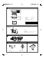 2
2
-
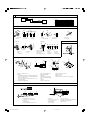 3
3
-
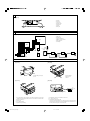 4
4
-
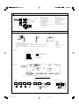 5
5
-
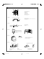 6
6
-
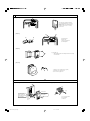 7
7
-
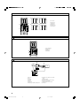 8
8
-
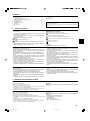 9
9
-
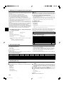 10
10
-
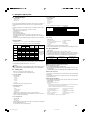 11
11
-
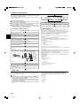 12
12
-
 13
13
-
 14
14
-
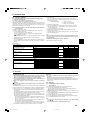 15
15
-
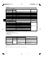 16
16
-
 17
17
-
 18
18
-
 19
19
-
 20
20
-
 21
21
-
 22
22
-
 23
23
-
 24
24
-
 25
25
-
 26
26
-
 27
27
-
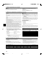 28
28
-
 29
29
-
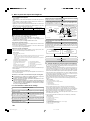 30
30
-
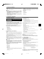 31
31
-
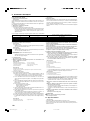 32
32
-
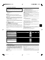 33
33
-
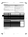 34
34
-
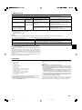 35
35
-
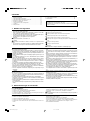 36
36
-
 37
37
-
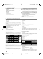 38
38
-
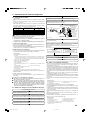 39
39
-
 40
40
-
 41
41
-
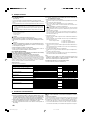 42
42
-
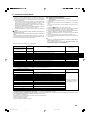 43
43
-
 44
44
-
 45
45
-
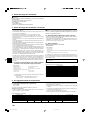 46
46
-
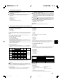 47
47
-
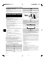 48
48
-
 49
49
-
 50
50
-
 51
51
-
 52
52
-
 53
53
-
 54
54
-
 55
55
-
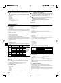 56
56
-
 57
57
-
 58
58
-
 59
59
-
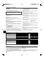 60
60
-
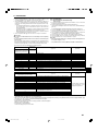 61
61
-
 62
62
-
 63
63
-
 64
64
-
 65
65
-
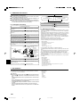 66
66
-
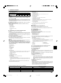 67
67
-
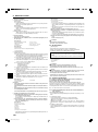 68
68
-
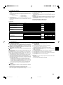 69
69
-
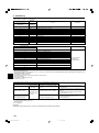 70
70
-
 71
71
-
 72
72
-
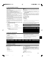 73
73
-
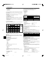 74
74
-
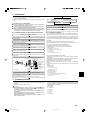 75
75
-
 76
76
-
 77
77
-
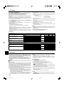 78
78
-
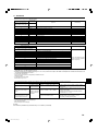 79
79
-
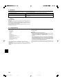 80
80
-
 81
81
-
 82
82
-
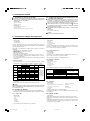 83
83
-
 84
84
-
 85
85
-
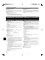 86
86
-
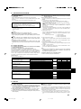 87
87
-
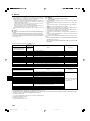 88
88
-
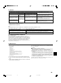 89
89
-
 90
90
-
 91
91
-
 92
92
-
 93
93
-
 94
94
-
 95
95
-
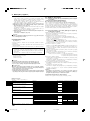 96
96
-
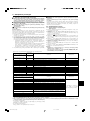 97
97
-
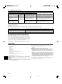 98
98
-
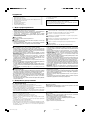 99
99
-
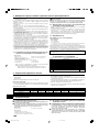 100
100
-
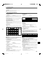 101
101
-
 102
102
-
 103
103
-
 104
104
-
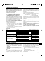 105
105
-
 106
106
-
 107
107
-
 108
108
-
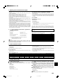 109
109
-
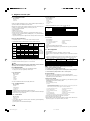 110
110
-
 111
111
-
 112
112
-
 113
113
-
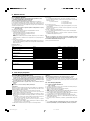 114
114
-
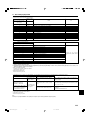 115
115
-
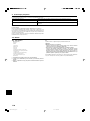 116
116
-
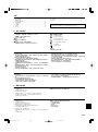 117
117
-
 118
118
-
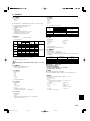 119
119
-
 120
120
-
 121
121
-
 122
122
-
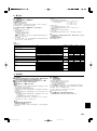 123
123
-
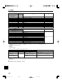 124
124
-
 125
125
-
 126
126
-
 127
127
-
 128
128


Mitsubishi SEZ-KD25VAL Bedienungsanleitung
- Kategorie
- Split-System-Klimaanlagen
- Typ
- Bedienungsanleitung
- Dieses Handbuch eignet sich auch für
in anderen Sprachen
- English: Mitsubishi SEZ-KD25VAL Owner's manual
- français: Mitsubishi SEZ-KD25VAL Le manuel du propriétaire
- español: Mitsubishi SEZ-KD25VAL El manual del propietario
- italiano: Mitsubishi SEZ-KD25VAL Manuale del proprietario
- русский: Mitsubishi SEZ-KD25VAL Инструкция по применению
- Nederlands: Mitsubishi SEZ-KD25VAL de handleiding
- português: Mitsubishi SEZ-KD25VAL Manual do proprietário
- dansk: Mitsubishi SEZ-KD25VAL Brugervejledning
- svenska: Mitsubishi SEZ-KD25VAL Bruksanvisning
- Türkçe: Mitsubishi SEZ-KD25VAL El kitabı
Verwandte Artikel
Andere Dokumente
-
Mitsubishi Electric KOMPAKT MXZ-2D33VA Installationsanleitung
-
-
-
 Mitsubishi Electronics AR-FL32MA Benutzerhandbuch
-
-
mundoclima Series MUCR-H8 “Duct Full Inverter H8” Installationsanleitung
-
-
-
Chariot Carriers Merci Installationsanleitung
-
