EuroLite LED WMS 8-fold Set RBG Benutzerhandbuch
- Kategorie
- Stroboskope
- Typ
- Benutzerhandbuch

©
Copyright
Nachdruck verboten!
Reproduction prohibited!
Réproduction interdit!
Prohibida toda reproducción.
Für weiteren Gebrauch aufbewahren!
Keep this manual for future needs!
Gardez ce mode d’emploi pour des
utilisations ultérieures!
Guarde este manual para posteriores usos.
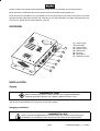
BEDIENUNGSANLEITUNG
USER MANUAL
MODE D'EMPLOI
MANUAL DEL USUARIO
LED WMS 8-fold Set
RBG Lighting Effect

51930200X18NXS_V_1_0.DOC
2/35
MULTI-LANGUAGE-INSTRUCTIONS
Inhaltsverzeichnis
Table of contents
Sommaire
Contenido
EINFÜHRUNG................................................................................................................................................... 4
SICHERHEITSHINWEISE................................................................................................................................. 4
BESTIMMUNGSGEMÄSSE VERWENDUNG .................................................................................................. 5
GERÄTEÜBERSICHT....................................................................................................................................... 6
INSTALLATION ................................................................................................................................................ 7
Montage ......................................................................................................................................................... 7
Hängende Installation .................................................................................................................................... 7
BEDIENUNG ..................................................................................................................................................... 8
Chaser............................................................................................................................................................ 8
Stand Alone-Betrieb....................................................................................................................................... 9
DMX-gesteuerter Betrieb ............................................................................................................................... 9
Adressierung des Projektors.......................................................................................................................... 9
DMX-Protokoll................................................................................................................................................ 9
Dimmer Steuerkanäle .................................................................................................................................. 10
REINIGUNG UND WARTUNG........................................................................................................................ 10
Sicherungswechsel ...................................................................................................................................... 11
TECHNISCHE DATEN.................................................................................................................................... 11
INTRODUCTION ............................................................................................................................................. 12
SAFETY INSTRUCTIONS .............................................................................................................................. 12
OPERATING DETERMINATIONS.................................................................................................................. 13
OVERVIEW ..................................................................................................................................................... 14
INSTALLATION .............................................................................................................................................. 14
Rigging ......................................................................................................................................................... 14
Hanging installation...................................................................................................................................... 14
OPERATION ................................................................................................................................................... 16
Chaser.......................................................................................................................................................... 16
Stand Alone operation.................................................................................................................................. 16
DMX-controlled operation ............................................................................................................................ 16
Addressing ................................................................................................................................................... 17
DMX-protocol ............................................................................................................................................... 17
Dimmer Control Channels............................................................................................................................ 18
CLEANING AND MAINTENANCE ................................................................................................................. 18
Replacing the fuse ....................................................................................................................................... 19
TECHNICAL SPECIFICATIONS..................................................................................................................... 19

51930200X18NXS_V_1_0.DOC
3/35
INTRODUCTION ............................................................................................................................................. 20
INSTRUCTIONS DE SÉCURITÉ .................................................................................................................... 20
EMPLOI SELON LES PRESCRIPTIONS....................................................................................................... 21
APERÇUE DES PARTIES .............................................................................................................................. 22
INSTALLATION .............................................................................................................................................. 22
Montage ....................................................................................................................................................... 22
Installation suspendu ................................................................................................................................... 23
MANIEMENT................................................................................................................................................... 24
Chaser.......................................................................................................................................................... 24
Opération Stand Alone................................................................................................................................. 24
Contrôle par DMX ........................................................................................................................................ 24
Codage du projecteur................................................................................................................................... 25
Protocôle DMX............................................................................................................................................. 25
Canal de Contrôle Dimmer .......................................................................................................................... 26
NETTOYAGE ET MAINTENANCE................................................................................................................. 26
Remplacer le fusible..................................................................................................................................... 27
CARACTÉRISTIQUES TECHNIQUES........................................................................................................... 27
INTRODUCCIÓN............................................................................................................................................. 28
INSTRUCCIONES DE SEGURIDAD .............................................................................................................. 28
INSTRUCCIONES DE MANEJO .................................................................................................................... 29
DESCRIPCIÓN DE LAS PARTES.................................................................................................................. 30
INSTALACIÓN ................................................................................................................................................ 30
Montaje ........................................................................................................................................................ 30
Instalación suspendida ................................................................................................................................ 31
OPERACIÓN ................................................................................................................................................... 32
Chaser.......................................................................................................................................................... 32
Operación Stand Alone................................................................................................................................ 32
Control por DMX .......................................................................................................................................... 32
Direccionamiento del proyector ................................................................................................................... 33
Protócolo DMX............................................................................................................................................. 33
Canal de Control de Dimmer ....................................................................................................................... 34
LIMPIEZA Y MANTENIMIENTO..................................................................................................................... 34
Reemplazar el fusible................................................................................................................................... 35
ESPECIFICACIONES TÉCNICAS.................................................................................................................. 35
Das neueste Update dieser Bedienungsanleitung finden Sie im Internet unter:
You can find the latest update of this user manual in the Internet under:
Vous pouvez trouvez la dernière version de ce mode d'emploi dans l'Internet sous:
Vd. puede encontrar la versión más reciente de este manual en el Internet bajo:
www.eurolite.de

51930200X18NXS_V_1_0.DOC
4/35
BEDIENUNGSANLEITUNG
LED WMS 8-fach Set RBG
Lichteffekt
Lesen Sie vor der ersten Inbetriebnahme zur eigenen Sicherheit diese Bedienungsanleitung sorgfältig durch!
Alle Personen, die mit der Aufstellung, Inbetriebnahme, Bedienung, Wartung und Instandhaltung dieses
Gerätes zu tun haben, müssen
- entsprechend qualifiziert sein
- diese Bedienungsanleitung genau beachten
- die Bedienungsanleitung als Teil des Produkts betrachten
- die Bedienungsanleitung während der Lebensdauer des Produkts behalten
- die Bedienungsanleitung an jeden nachfolgenden Besitzer oder Benutzer des Produkts weitergeben
- sicherstellen, dass gegebenenfalls jede erhaltene Ergänzung in die Anleitung einzuführen ist
EINFÜHRUNG
Wir freuen uns, dass Sie sich für einen EUROLITE LED WMS 8-fach Set RBG entschieden haben. Sie
haben hiermit ein leistungsstarkes und vielseitiges Gerät erworben. Der LED WMS 8-fach SET RBG verfügt
über ein eingebautes Mikrofon.
Nehmen Sie den EUROLITE LED WMS 8-fach SET RBG aus der Verpackung.
Prüfen Sie zuerst, ob Transportschäden vorliegen. In diesem Fall nehmen Sie das Gerät nicht in Betrieb und
setzen sich bitte mit Ihrem Fachhändler in Verbindung.
SICHERHEITSHINWEISE
ACHTUNG!
Seien Sie besonders vorsichtig beim Umgang mit gefährlicher Netzspannung. Bei die-
ser Spannung können Sie einen lebensgefährlichen elektrischen Schlag erhalten!
Dieses Gerät hat das Werk in sicherheitstechnisch einwandfreiem Zustand verlassen. Um diesen Zustand zu
erhalten und einen gefahrlosen Betrieb sicherzustellen, muss der Anwender die Sicherheitshinweise und die
Warnvermerke unbedingt beachten, die in dieser Bedienungsanleitung enthalten sind.

51930200X18NXS_V_1_0.DOC
5/35
Unbedingt lesen:
Bei Schäden, die durch Nichtbeachtung der Anleitung verursacht werden, erlischt der Garantiean-
spruch. Für daraus resultierende Folgeschäden übernimmt der Hersteller keine Haftung.
Das Gerät darf nicht in Betrieb genommen werden, nachdem es von einem kalten in einen warmen Raum
gebracht wurde. Das dabei entstehende Kondenswasser kann unter Umständen Ihr Gerät zerstören. Lassen
Sie das Gerät solange uneingeschaltet, bis es Zimmertemperatur erreicht hat!
Der Aufbau entspricht der Schutzklasse I. Der Netzstecker darf nur an eine Schutzkontakt-Steckdose
angeschlossen werden.
Lassen Sie die Netzleitung nicht mit anderen Kabeln in Kontakt kommen! Seien Sie vorsichtig beim Umgang
mit Netzleitungen und -anschlüssen. Fassen Sie diese Teile nie mit nassen Händen an!
Vergewissern Sie sich, dass die anzuschließende Netzspannung nicht höher ist als auf der Rückseite ange-
geben. Stecken Sie die Netzleitung nur in geeignete Schutzkontaktsteckdosen ein.
Achten Sie darauf, dass die Netzleitung nicht gequetscht oder durch scharfe Kanten beschädigt werden
kann. Überprüfen Sie das Gerät und die Netzleitung in regelmäßigen Abständen auf Beschädigungen.
Gerät bei Nichtbenutzung und vor jeder Reinigung vom Netz trennen! Fassen Sie dazu den Netzstecker an
der Griffläche an und ziehen Sie niemals an der Netzleitung!
Bei der ersten Inbetriebnahme kann es zu Rauch- und Geruchserzeugung kommen. Hierbei handelt es sich
nicht um eine Störung des Gerätes.
GESUNDHEITSRISIKO!
Blicken Sie niemals direkt in die Lichtquelle, da bei empfindlichen Menschen u. U.
epileptische Anfälle ausgelöst werden können (gilt besonders für Epileptiker)!
Kinder und Laien vom Gerät fern halten!
BESTIMMUNGSGEMÄSSE VERWENDUNG
Bei diesem Gerät handelt es sich um einen Effektstrahler, mit dem sich dekorative Lichteffekte erzeugen
lassen. Dieses Produkt ist nur für den Anschluss an 230 V, 50 Hz Wechselspannung zugelassen und wurde
ausschließlich zur Verwendung in Innenräumen konzipiert.
Dieses Gerät ist für professionelle Anwendungen, z. B. auf Bühnen, in Diskotheken, Theatern etc.
vorgesehen.
Lichteffekte sind nicht für den Dauerbetrieb konzipiert. Denken Sie daran, dass konsequente Betriebspausen
die Lebensdauer des Gerätes erhöhen.
Das Gerät darf aus Sicherheitsgründen nie über einer Fläche montiert werden, auf der sich Personen
aufhalten können.
Vermeiden Sie Erschütterungen und jegliche Gewaltanwendung bei der Installation oder Inbetriebnahme des
Gerätes.
Achten Sie bei der Wahl des Installationsortes darauf, dass das Gerät nicht zu großer Hitze, Feuchtigkeit
und Staub ausgesetzt wird. Vergewissern Sie sich, dass keine Kabel frei herumliegen. Sie gefährden Ihre
eigene und die Sicherheit Dritter!
Das Bildzeichen
---m
bezeichnet den Mindestabstand zu beleuchteten Gegenständen. Der Abstand
zwischen Lichtaustritt und der zu beleuchteten Fläche darf 0,5 Meter nicht unterschreiten!

51930200X18NXS_V_1_0.DOC
6/35
MODE
SL/SP
UP
DOWN
E
L
E
C
T
R
0
N
IC
S
&
S
O
F
T
W
A
R
E
B
Y
IN
T
E
L
L
IW
AY
IN
C
.,
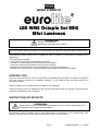
Channel 1: Rainbow Color
Channel 4:
Channel 6: Sound Active
Channel 2: Dimmer Of Red , 0-100%
Channel 3: Dimmer Of Green, 0-100%
Dimmer Of Blue, 0-100%
Channel 5: Strobe Effect 80-1200/min
CHANNEL ASSIGNMENTS
WARNING
1.PUT
D
OWN
V
ENTILATE
A
REA
2.KEEP
I
T
D
RY
3.FOR
I
NSIDE
U
SE
O
NLY
D
M
X512
:PIN
S
3=SIGNAL+
2=SIGNAL -
1=
DMX512 INPUT
DMX512 OUTPUT
OFF
ON
POW
ER
DC12V
/ SIGNAL
OUTPUT
M
IC
A
U
D
I
F
U
S
E
/
1
A
A
C
2
3
0
V
/5
0
H
Z
1
2
0
V
/6
0
H
Z
R
E
P
L
A
C
E
O
N
L
Y
W
IT
H
S
A
M
E
S
IZ
E
A
N
D
T
Y
P
E
O
F
F
U
S
E
C
A
UTIO
N
PROVIDES
P
OWER
A
ND
C
ONTROL F
OR
UP
T
O
8
C
HAMELEON
F
IXTURES
O
NLY
Set
D
MX-512
A
ddress
Select
S
laver
D
MX-512
Control
A
ddress
Use Upand Down keyTo Setup
1. DMX-512Address 001~255
2. Builtin Chase 1~9
3. Mode1,2,4,8
Select
B
uilt-in
C
hases
Chase
1
~Chase
9
(
N
ot
D
igital
i
nput
)
Adjust SlopeOf Chase
From
0
%~100%
Adjust SpeedOf Chase
From
1
~500/min
** Mode
8
:Every
E
ight SlaverAddress
V
alue
(
6
c
hannel)
Control ofChase
CHANNEL
7-12
CHANNEL
13-18
CHANNEL
19-24
CHANNEL
25-30
CHANNEL
31-36
CHANNEL
37-42
CHANNEL
43-48
CHANNEL
1-6
** Mode1:Every S
laver Address
V
alue
(
48channel)
** Mode
2
:Every
T
wo
S
laver Address
V
alue
(
24 channel)
** Mode
4
:Every FourSlaver Address
V
alue
(
12
c
hannel)
CHANNEL
13-18
CHANNEL
25-30
CHANNEL
37-42
CHANNEL
1-6
CHANNEL
1-6
CHANNEL
13-18
CHANNEL
25-30
CHANNEL
37-42
A
B
B
C
C
D
D
A
CHANNEL
1-6
CHANNEL
7-12
CHANNEL
7-12
CHANNEL
7-12
CHANNEL
7-12
CHANNEL
1-6
CHANNEL
1-6
CHANNEL
1-6
A
A
A
AB
B
B
B
CHANNEL
1-6
A
CHANNEL
1-6
A
CHANNEL
1-6
A
CHANNEL
1-6
A
CHANNEL
1-6
A
CHANNEL
1-6
A
CHANNEL
1-6
A
CHANNEL
1-6
A
Select 3Control Modes
MODE :
KEY
UP andDOWN
KEY
:
SL/SP :
KEY
1
2
3
4
5
6
7
Achten Sie bei der Projektormontage, beim Projektorabbau und bei der Durchführung von Servicearbeiten
darauf, dass der Bereich unterhalb des Montageortes abgesperrt ist.
Die maximale Umgebungstemperatur t
a
= 45° C darf niemals überschritten werden.
Nehmen Sie das Gerät erst in Betrieb, nachdem Sie sich mit seinen Funktionen vertraut gemacht haben.
Lassen Sie das Gerät nicht von Personen bedienen, die sich nicht mit dem Gerät auskennen. Wenn Geräte
nicht mehr korrekt funktionieren, ist das meist das Ergebnis von unfachmännischer Bedienung!
Soll das Gerät transportiert werden, verwenden Sie bitte die Originalverpackung, um Transportschäden zu
vermeiden.
Beachten Sie bitte, dass eigenmächtige Veränderungen an dem Gerät aus Sicherheitsgründen verboten
sind.
Der Serienbarcode darf niemals vom Gerät entfernt werden, da ansonsten der Garantieanspruch erlischt.
Wird das Gerät anders verwendet als in dieser Bedienungsanleitung beschrieben, kann dies zu Schäden am
Produkt führen und der Garantieanspruch erlischt. Außerdem ist jede andere Verwendung mit Gefahren, wie
z. B. Kurzschluss, Brand, elektrischem Schlag, Lampenexplosion, Abstürzen etc. verbunden.
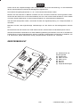
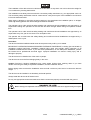
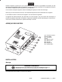
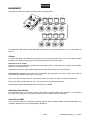
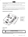
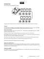
GERÄTEÜBERSICHT
(1) Netzanschluß und
Sicherungshalter
(2) Netzschalter
(3) DMX-512 OUT
(4) DMX-512 IN
(5) DC OUT
(6) Mikrofon
(7) Empfindlichkeitsregler

51930200X18NXS_V_1_0.DOC
7/35
INSTALLATION
Montage
Achten Sie bei der Installation des Gerätes bitte darauf, dass sich im Abstand
von mind. 0,5 m keine leicht entflammbaren Materialien (Deko, etc.) befinden.
BRANDGEFAHR!
Das Gerät kann sowohl hängend als auch stehend installiert werden.
Hängende Installation
LEBENSGEFAHR!
Bei der Installation sind insbesondere die Bestimmungen der BGV C1 (vormals VBG 70)
und DIN VDE 0711-217 zu beachten! Die Installation darf nur vom autorisierten Fachhan-
del ausgeführt werden!
Die Aufhängevorrichtungen des Gerätes muss so gebaut und bemessen sein, dass sie 1 Stunde lang ohne
dauernde schädliche Deformierung das 10-fache der Nutzlast aushalten kann.
Die Installation muss immer mit einer zweiten, unabhängigen Aufhängung, z. B. einem geeigneten Fangnetz,
erfolgen. Diese zweite Aufhängung muss so beschaffen und angebracht sein, dass im Fehlerfall der
Hauptaufhängung kein Teil der Installation herabfallen kann.
Während des Auf-, Um- und Abbaus ist der unnötige Aufenthalt im Bereich von Bewegungsflächen, auf
Beleuchterbrücken, unter hochgelegenen Arbeitsplätzen sowie an sonstigen Gefahrbereichen verboten.
Der Unternehmer hat dafür zu sorgen, dass sicherheitstechnische und maschinentechnische Einrichtungen
vor der ersten Inbetriebnahme und nach wesentlichen Änderungen vor der Wiederinbetriebnahme durch
Sachverständige geprüft werden.
Der Unternehmer hat dafür zu sorgen, dass sicherheitstechnische und maschinentechnische Einrichtungen
mindestens alle vier Jahre durch einen Sachverständigen im Umfang der Abnahmeprüfung geprüft werden.
Der Unternehmer hat dafür zu sorgen, dass sicherheitstechnische und maschinentechnische Einrichtungen
mindestens einmal jährlich durch einen Sachkundigen geprüft werden.
Vorgehensweise:
Das Gerät sollte idealerweise außerhalb des Aufenthaltsbereiches von Personen installiert werden.
WICHTIG! ÜBERKOPFMONTAGE ERFORDERT EIN HOHES MAß AN ERFAHRUNG. Dies beinhaltet (aber
beschränkt sich nicht allein auf) Berechnungen zur Definition der Tragfähigkeit, verwendetes Installations-
material und regelmäßige Sicherheitsinspektionen des verwendeten Materials und des Gerätes. Versuchen
Sie niemals, die Installation selbst vorzunehmen, wenn Sie nicht über eine solche Qualifikation verfügen,
sondern beauftragen Sie einen professionellen Installateur. Unsachgemäße Installationen können zu
Verletzungen und/oder zur Beschädigung von Eigentum führen.
Das Gerät muss außerhalb des Handbereichs von Personen installiert werden.
Das Gerät darf niemals frei schwingend im Raum befestigt werden.
Achtung: Hängend installierte Geräte können beim Herabstürzen erhebliche Verletzungen verursachen!
Wenn Sie Zweifel an der Sicherheit einer möglichen Installationsform haben, installieren Sie das Gerät
NICHT!
Vergewissern Sie sich vor der Montage, dass die Montagefläche mindestens die 10-fache Punktbelastung
des Eigengewichtes des Gerätes aushalten kann.

51930200X18NXS_V_1_0.DOC
8/35
Das Gerät muss absolut plan befestigt werden.
Achten Sie bei der Installation des Gerätes darauf, dass Sie es über alle Befestigungslöcher anbringen.
Verwenden Sie geeignete Schrauben und vergewissern Sie sich, dass die Schrauben fest mit dem
Untergrund verbunden sind.
LEBENSGEFAHR!
Vor der ersten Inbetriebnahme muss die Einrichtung durch einen Sachverständigen geprüft werden!
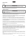
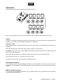
BEDIENUNG
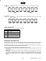
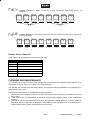
Stellen Sie die gewünschten Adressen an den Spots ein:
1
2
3
4
8
7
6
5
1
2
3
4
5
6
7
8
9
0
1
2
3
4
5
6
7
8
9
0
1
2
3
4
5
6
7
8
9
0
1
2
3
4
5
6
7
8
9
0
1
2
3
4
5
6
7
8
9
0
1
2
3
4
5
6
7
8
9
0
1
2
3
4
5
6
7
8
9
0
1
2
3
4
5
6
7
8
9
0
MODE
SL/SP
UP
DOWN
E
L
E
C
T
R
0
N
IC
S
&
S
O
F
T
W
A
R
E
B
Y
IN
T
E
L
L
I
W
AY
I
N
C
.,
C
h
a
n
n
e
l
1
:
R
a
i
n
b
o
w
C
o
l
o
r
C
h
a
n
n
e
l
4
:
C
h
a
n
n
e
l
6
:
S
o
u
n
d
A
c
t
i
v
e
C
h
a
n
n
e
l
2
:
D
i
m
m
e
r
O
f
R
e
d
,
0
-
1
0
0
%
C
h
a
n
n
e
l
3
:
D
i
m
m
e
r
O
f
G
r
e
e
n
,
0
-
1
0
0
%
D
i
m
m
e
r
O
f
B
l
u
e
,
0
-
1
0
0
%
C
h
a
n
n
e
l
5
:
S
t
r
o
b
e
E
f
f
e
c
t
8
0
-
1
2
0
0
/
m
i
n
CHA
NNELA
SSIG
NMENTS
WARNING
1.PUTDOWN VENTILATEAREA
2.KEEPIT DRY
3.FORINSIDE USE ONLY
D
M
X
5
1
2
:
P
I
N
S
3=SIG
NAL+
2=SIGNAL-
1
=
D
M
X
5
1
2
I
N
P
U
T
D
M
X
5
1
2
O
U
T
P
U
T
O
F
F
ON
POW
ER
D
C
12
V
/S
IG
N
A
L
O
U
TP
U
T
M
IC
A
U
D
I
F
U
S
E
/
1
A
A
C
2
3
0
V
/
5
0
H
Z
1
2
0
V
/
6
0
H
Z
R
E
P
L
A
C
E
O
N
L
Y
W
I
T
H
S
A
M
E
S
I
Z
E
A
N
D
T
Y
P
E
O
F
F
U
S
E
C
A
U
T
I
O
N
PROVIDES
P
OWER
A
ND
C
ONTROL
F
OR
UP
T
O
8
C
HAMELEON
F
IXTURES
O
NLY
Set
D
MX-512
A
ddress
Select
S
laver
D
MX-512
Control
A
ddress
Use
U
p
a
nd
D
own
k
ey
T
o
S
etup
1.
D
M
X-512
A
ddress
0
01~255
2.
B
uilt
i
n
C
hase
1
~9
3.
M
ode
1
,2,4,8
Select
B
uilt-in
C
hases
Chase
1
~Chase
9
(
N
ot
D
igital
i
nput
)
Adjust
S
lope
O
f
C
hase
From
0
%~100%
Adjust
S
peed
O
f
C
hase
From
1
~500/min
**
M
ode
8
:E
v
ery
E
i
ght
S
lave
r
A
ddress
V
alue
(
6
c
hanne
l
)
Control
o
f
C
hase
C
HANNEL
7
-12
CH
A
N
N
E
L
1
3
-18
CHANN
E
L
19
-
24
CH
A
N
N
E
L
25-3
0
C
HA
NNE
L
31
-36
CHANNEL
37-42
CH
A
N
N
E
L
43-
48
CHANN
E
L
1
-6
**
M
ode
1
:
Every
S
la
ve
r
A
ddress
V
a
l
ue
(
4
8channel
)
*
*
M
o
d
e
2
:
E
v
ery
T
wo
S
la
v
er
A
d
d
res
s
V
a
l
ue
(
2
4
c
h
a
n
ne
l
)
**
M
o
de
4
:Every
F
our
S
laver
A
ddr
e
ss
V
alue
(
12
c
hannel
)
CH
A
N
NE
L
1
3
-18
CHANN
E
L
25
-30
CHANNEL
37
-4
2
C
HA
N
N
E
L
1
-6
C
H
ANNEL
1-6
CH
A
N
N
E
L
13
-18
C
HA
NNE
L
2
5-30
CH
A
NNEL
37
-42
A
B
B
C
C
D
D
A
C
HA
N
N
E
L
1
-6
CH
A
N
N
E
L
7
-1
2
C
HA
N
N
E
L
7-12
CHAN
N
EL
7
-1
2
CHAN
N
E
L
7-
12
C
HA
N
N
E
L
1
-6
C
HA
N
N
E
L
1
-6
CHAN
N
E
L
1
-6
A
A
A
A
B
B
B
B
CHAN
NEL
1-6
A
C
HA
NNE
L
1-6
A
CHANNEL
1-6
A
CHAN
N
EL
1-6
A
C
HA
N
N
E
L
1
-6
A
CHAN
N
EL
1-6
A
C
HANN
E
L
1
-6
A
CHANNEL
1
-6
A
Select
3
C
ontrol
M
odes
MODE :
KEY
UP
a
nd
D
OWN
KEY
:
SL/SP :
KEY
Wenn Sie das Gerät an die Spannungsversorgung angeschlossen haben, nimmt der EUROLITE LED WMS
8-fach SET RBG den Betrieb auf.
Chaser
Ein Chaser ist eine Aneinanderreihung von verschiedenen Programmen, die nacheinander abgespielt
werden. Mit dem der EUROLITE LED WMS 8-fach Set RBG lassen sich bis zu 9 verschiedene Chaser mit
bis zu 500 Steps auswählen.
Auswählen eines Chasers
Drücken Sie die MODE Taste. Wählen Sie den gewünschten Chaser (che1 – che8) über die UP oder DOWN
Tasten aus. (che9 ist Musikgesteuert)
Wählen Sie den gewünschten Chaser Wert über die SP/SL Tasten aus.(Step Time oder Überblendzeit)
Zum Beispiel: Sie wählen che1 mit der MODE Taste und dann wählen Sie SP/SL für den gewünschten
Step Time oder Überblendzeit Wert.
P001 hat einen Step Time Wert von 1 Mal/Minute, P500 hat einen Step Time Wert von 500 Mal/Minute.
L001 hat eine Überblendzeit von 1%, L100 hat eine Überblendzeit von 100%.
Die gewünschten Werte können jeweils mit den UP oder DOWN Tasten gewählt werden.

51930200X18NXS_V_1_0.DOC
9/35
UP
LI
UP
L2
Stand Alone-Betrieb
Der LED WMS 8-fach Set RBG lässt sich im Stand Alone-Betrieb ohne Controller einsetzen. Dank des
eingebauten Mikrofones ist kein Controller nötig, und das Licht wird musikgesteuert durch den Raum
geworfen.
DMX-gesteuerter Betrieb
Über Ihren DMX-Controller können Sie die einzelnen Geräte individuell ansteuern. Dabei hat jeder DMX-
Kanal eine andere Belegung mit verschiedenen Eigenschaften.
Adressierung des Projektors
Über das Control Board können Sie die DMX Startadresse definieren. Die Startadresse ist der erste Kanal,
auf den der Projektor auf Signale vom Controller reagiert.
Um die Startadresse einzustellen drücken Sie die MODE Taste, bis das Display "A001" anzeigt.
Ansteuerung:
Nachdem Sie die Startadresse definiert haben, können Sie den LED WMS 8-fach Set RBG über Ihren
Controller ansteuern.
Bitte beachten Sie:
Schalten Sie den LED WMS 8-fach Set RBG ein. Das Gerät prüft, ob DMX-512 Daten empfangen werden
oder nicht. Wenn Daten empfangen werden, blinkt die Kontroll-LED. Werden keine Daten empfangen,
leuchtet die Kontroll-LED permanent.
Die Meldung erscheint
-wenn kein 3-poliges XLR-Kabel (DMX Signalkabel vom Controller) in die DMX-Eingangsbuchse des LED
WMS 8-fach Set RBG gesteckt wurde.
-wenn der Controller ausgeschaltet oder defekt ist.
-das Kabel oder der Stecker defekt ist oder das Signalkabel nicht richtig eingesteckt ist.
Achtung: Am letzten Projektor muss die DMX-Leitung durch einen 120
Ω
. Widerstand abgeschlossen
werden damit die Geräte korrekt funktionieren.
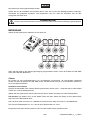
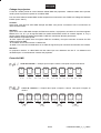
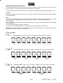
DMX-Protokoll
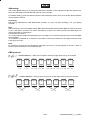
Steuerkanal 1 - Jeder Spot belegt 6 Kanäle. Acht Spots belegen 48 Kanäle.
1~6 7~12 13~18 19~24 25~30 31~36 37~42 42~48
Steuerkanal 2 – Alle 2 Spots belegen 6 Kanäle. Acht Spots belegen 24 Kanäle.
1~6 7~12 13~18 19~24

51930200X18NXS_V_1_0.DOC
10/35
UP
L4
UP
L8
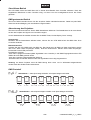
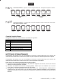
Steuerkanal 3 – Spots 1-4 und 5-8 belegen 6 Kanäle. Acht Spots belegen 12 Kanäle
1~6 7~12
Steuerkanal 4 – Jeder Spot belegt die selben 6 Kanäle wie jeder andere. Acht Spots
belegen 6 Kanäle
1~6 1~6 1~6 1~6 1~6 1~6 1~6 1~6
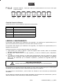
Dimmer Steuerkanäle
Lineare Farbänderung gemäß der Bewegung des Reglers.
Kanal: Eigenschaft:
1 Rainboweffekt
2 Rot 0 - 100%
3 Grün 0 - 100%
4 Blau 0 – 100%
5 Strobe Effekt 80 – 1200 Flash/Min.
6 Musikgesteuert ON/OFF
REINIGUNG UND WARTUNG
Der Unternehmer hat dafür zu sorgen, dass sicherheitstechnische und maschinentechnische Einrichtungen
mindestens alle vier Jahre durch einen Sachverständigen im Umfang der Abnahmeprüfung geprüft werden.
Der Unternehmer hat dafür zu sorgen, dass sicherheitstechnische und maschinentechnische Einrichtungen
mindestens einmal jährlich durch einen Sachkundigen geprüft werden.
Dabei muss unter anderem auf folgende Punkte besonders geachtet werden:
1) Alle Schrauben, mit denen das Gerät oder Geräteteile montiert sind, müssen fest sitzen und dürfen nicht
korrodiert sein.
2) An Gehäuse, Befestigungen und Montageort (Decke, Abhängung, Traverse) dürfen keine Verformungen
sichtbar sein.
3) Die elektrischen Anschlussleitungen dürfen keinerlei Beschädigungen, Materialalterung (z.B. poröse
Leitungen) oder Ablagerungen aufweisen. Weitere, auf den jeweiligen Einsatzort und die Nutzung
abgestimmte Vorschriften werden vom sachkundigen Installateur beachtet und Sicherheitsmängel
behoben.

51930200X18NXS_V_1_0.DOC
11/35
Vor Wartungsarbeiten unbedingt allpolig vom Netz trennen!
LEBENSGEFAHR!
Das Gerät sollte regelmäßig von Verunreinigungen wie Staub usw. gereinigt werden. Verwenden Sie zur
Reinigung ein fusselfreies, angefeuchtetes Tuch. Auf keinen Fall Alkohol oder irgendwelche Lösungsmittel
zur Reinigung verwenden!
Im Geräteinneren befinden sich keine zu wartenden Teile. Wartungs- und Servicearbeiten sind ausschließ-
lich dem autorisierten Fachhandel vorbehalten!
Bitte beachten Sie auch die Hinweise unter "Lampeninstallation/Lampenwechsel".
Sicherungswechsel
Wenn die Feinsicherung des Gerätes defekt ist, darf diese nur durch eine Sicherung gleichen Typs ersetzt
werden.
Vor dem Sicherungswechsel ist das Gerät allpolig von der Netzspannung zu trennen (Netzstecker
ziehen).
Vorgehensweise:
Schritt 1: Öffnen Sie den Sicherungshalter an der Geräterückseite mit einem passenden
Schraubendreher.
Schritt 2: Entfernen Sie die defekte Sicherung aus dem Sicherungshalter.
Schritt 3: Setzen Sie die neue Sicherung in den Sicherungshalter ein.
Schritt 4: Setzen Sie den Sicherungshalter wieder im Gehäuse ein.
Sollten einmal Ersatzteile benötigt werden, verwenden Sie bitte nur Originalersatzteile.
Wenn die Anschlussleitung dieses Gerätes beschädigt wird, muss sie durch eine besondere Anschluss-
leitung ersetzt werden, die von Ihrem Fachhändler erhältlich ist.
Sollten Sie noch weitere Fragen haben, steht Ihnen Ihr Fachhändler jederzeit gerne zur Verfügung.
TECHNISCHE DATEN
Spannungsversorgung: 230 V AC, 50 Hz ~
Gesamtanschlusswert: 50 W
Musiksteuerung: über eingebautes Mikrofon
Maße (LxBxH): 260 x 140 x 60 mm
Gewicht: 6 kg
Sicherung: F 0,5 A, 250 V
Bitte beachten Sie: Technische Änderungen ohne vorherige Ankündigung und Irrtum vorbehalten.
30.04.2003 ©

51930200X18NXS_V_1_0.DOC
12/35
USER MANUAL
LED WMS 8-fold Set RBG
Lighting Effect
CAUTION!
Keep this device away from rain and moisture!
Unplug mains lead before opening the housing!
For your own safety, please read this user manual carefully before you initially start-up.
Every person involved with the installation, operation and maintenance of this device has to
- be qualilfied
- follow the instructions of this manual
- consider this manual to be part of the total product
- keep this manual for the entire service life of the product
- pass this manual on to every further owner or user of the product
- include every supplementay update with the original manual
INTRODUCTION
Thank you for having chosen a EUROLITE LED WMS 8-fold set RBG. You will see you have acquired a
powerful and versatile device. The LED WMS 8-fold set RBG features a built-in microphone.
Unpack your LED WMS 8-fold set RBG.
Before you initially start-up, please make sure that there is no damage caused by transportation. Should
there be any, consult your dealer and do not use the device.
SAFETY INSTRUCTIONS
CAUTION!
Be careful with your operations. With a dangerous voltage you can suffer a dangerous
electric shock when touching the wires!
This device has left our premises in absolutely perfect condition. In order to maintain this condition and to
ensure a safe operation, it is absolutely necessary for the user to follow the safety instructions and warning
notes written in this user manual.
Important:
Damages caused by the disregard of this user manual are not subject to warranty. The dealer
will not accept liability for any resulting defects or problems.

51930200X18NXS_V_1_0.DOC
13/35
If the device has been exposed to drastic temperature fluctuation (e.g. after transportation), do not switch it
on immediately. The arising condensation water might damage your device. Leave the device switched off
until it has reached room temperature.
This device falls under protection-class I. The power plug must only be plugged into a protection class I
outlet.
Never let the power-cord come into contact with other cables! Handle the power-cord and all connections
with the mains with particular caution!
Make sure that the available voltage is not higher than stated on the rear panel.
Make sure that the power-cord is never crimped or damaged by sharp edges. Check the device and the
power-cord from time to time.
Always disconnect from the mains, when the device is not in use or before cleaning it. Only handle the
power-cord by the plug. Never pull out the plug by tugging the power-cord.
During the initial start-up some smoke or smell may arise. This is a normal process and does not necessarily
mean that the device is defective.
HEALTH HAZARD!
Never look directly into the light source, as sensitive persons may suffer an
epileptic shock (especially meant for epileptics)!
Keep away children and amateurs!
OPERATING DETERMINATIONS
This device is a lighting effect for creating decorative effects. This product is only allowed to be operated with
an alternating voltage of 230 V, 50 Hz and was designed for indoor use only.
This device is designed for professional use, e.g. on stages, in discotheques, theatres etc.
Lighting effects are not designed for permanent operation. Consistent operation breaks will ensure that the
device will serve you for a long time without defects.
The device must never be installed over areas, where persons may be seated or walk by.
Do not shake the device. Avoid brute force when installing or operating the device.
When choosing the installation-spot, please make sure that the device is not exposed to extreme heat,
moisture or dust. There should not be any cables lying around. You endanger your own and the safety of
others!
The symbol
---m
determines the minimum distance from lighted objects. The minimum distance
between light-output and the illuminated surface must be more than 0.5 meters.
Make sure that the area below the installation place is blocked when rigging, derigging or servicing the
fixture.
The maximum ambient temperature t
a
= 45° C must never be exceeded.
Operate the device only after having familiarized with its functions. Do not permit operation by persons not
qualified for operating the device. Most damages are the result of unprofessional operation!
Please use the original packaging if the device is to be transported.

51930200X18NXS_V_1_0.DOC
14/35
MODE
SL/SP
UP
DOWN
ELEC
TR
0N
IC
S
&
SO
FTW
A
RE
BY
IN
TELLIW
AY
IN
C.,
C
ha
nnel
1: R
ainbow
Co
lor
Channel
4
:
Ch
annel
6: Sou
nd
Ac
tive
C
hannel
2: D
im
mer
Of
Red
, 0-100%
Ch
annel
3: D
im
m
e
rO
fG
reen,
0-100%
D
im
m
er
O
f Blue,
0-10
0%
C
hann
el
5: S
trob
e
E
f
fec
t 80-1200/m
in
CHANNEL ASSIGNMENTS
WARNING
1.PUT
D
OWN
V
ENTILATE
A
REA
2.KEEP
I
T
D
RY
3.FOR
I
NSIDE
U
SE
O
NLY
DMX512 :PINS
3=S
IG
NAL+
2=SIGNAL -
1=
DMX512 INPUT
DMX512 OUTPUT
O
F
F
ON
POWER
DC12V / SIGNAL
OUTPUT
MIC
A
U
D
I
F
U
S
E
/
1
A
A
C
2
3
0
V
/
5
0
H
Z
1
2
0
V
/
6
0
H
Z
R
E
P
L
A
C
E
O
N
L
Y
W
IT
H
S
A
M
E
S
IZ
E
A
N
D
T
YP
E
O
F
F
U
S
E
CA
UTION
PROVIDES POWERAND CONTROL FOR
UP TO 8 CHAMELEONFIXTURES ONLY
Set DMX-512
A
ddress
Select
Slaver D
MX-512
Control Address
Use Upand Down keyTo Setup
1. DMX-512Address 001~255
2. Builtin Chase 1~9
3. Mode1,2,4,8
Select Built-in
C
hases
Chase
1
~Chase
9
(Not Digital input
)
Adjust Slope
O
f Chase
From
0
%~100%
Adjust Speed
O
f Chase
From
1
~500/min
**
M
ode
8
:Every
E
ight
S
laver
A
ddress
V
alue
(
6
c
hannel)
Control ofChase
CHANNEL
7-12
CHANNEL
13-18
CHANNEL
19-24
CHANNEL
25-30
CHANNEL
31-36
CHANNEL
37-42
CHANNEL
43-48
CHANNEL
1-6
**
M
ode
1
:Every
S
laver
A
ddress
V
alue
(
48channel)
**
M
ode
2
:Every
T
wo
S
laver
A
ddress
V
alue
(
24
c
hannel)
**
M
ode
4
:Every
F
our
S
laver
A
ddress
V
alue
(
12
c
hannel)
CHANNEL
13-18
CHANNEL
25-30
CHANNEL
37-42
CHANNEL
1
-6
CHANNEL
1-6
CHANNEL
13-18
CHANNEL
25-30
CHANNEL
37-42
A
B
BC
C
D
D
A
CHANNEL
1-6
CHANNEL
7-12
CHANNEL
7-12
CHANNEL
7-12
CHANNEL
7-12
CHANNEL
1-6
CHANNEL
1-6
CHANNEL
1-6
A
A
A
AB
B
B
B
CHANNEL
1-6
A
CHANNEL
1-6
A
CHANNEL
1-6
A
CHANNEL
1-6
A
CHANNEL
1-6
A
CHANNEL
1-6
A
CHANNEL
1-6
A
CHANNEL
1-6
A
Select3Control Modes
MODE :
KEY
UP andDOWN
KEY
:
SL/SP :
KEY
1
2
3
4
5
6
7
Please consider that unauthorized modifications on the device are forbidden due to safety reasons!
Never remove the serial barcode from the device as this would make the guarantee void.
If this device will be operated in any way different to the one described in this manual, the product may suffer
damages and the guarantee becomes void. Furthermore, any other operation may lead to dangers like short-
circuit, burns, electric shock, lamp explosion, crash etc.
OVERVIEW
(1) Power supply
and Fuseholder
(2) Power switch
(3) DMX-512 OUT
(4) DMX-512 IN
(5) DC OUT
(6) Microphone
(7) Sensitivity control
INSTALLATION
Rigging
DANGER OF FIRE!
When installing the device, make sure there is no highly-inflammable
material (decoration articles, etc.) within a distance of min. 0.5 m.
The device can be installed on the ground or on the wall or ceiling.
Hanging installation
DANGER TO LIFE!
Please consider the EN 60598-2-17 and the respective national norms during the
installation! The installation must only be carried out by an authorized dealer!

51930200X18NXS_V_1_0.DOC
15/35
The installation of the device has to be built and constructed in a way that it can hold 10 times the weight for
1 hour without any harming deformation.
The installation must always be secured with a secondary safety attachment, e.g. an appropriate catch net.
This secondary safety attachment must be constructed in a way that no part of the installation can fall down
if the main attachment fails.
When rigging, derigging or servicing the device staying in the area below the installation place, on bridges,
under high working places and other endangered areas is forbidden.
The operator has to make sure that safety-relating and machine-technical installations are approved by an
expert before taking into operation for the first time and after changes before taking into operation another
time.
The operator has to make sure that safety-relating and machine-technical installations are approved by an
expert after every four year in the course of an acceptance test.
The operator has to make sure that safety-relating and machine-technical installations are approved by a
skilled person once a year.
Procedure:
The device should be installed outside areas where persons may walk by or be seated.
IMPORTANT! OVERHEAD RIGGING REQUIRES EXTENSIVE EXPERIENCE, including (but not limited to)
calculating working load limits, installation material being used, and periodic safety inspection of all
installation material and the device. If you lack these qualifications, do not attempt the installation yourself,
but instead use a professional structural rigger. Improper installation can result in bodily injury and or
damage to property.
The device has to be installed out of the reach of people.
The device must never be fixed swinging freely in the room.
Caution: Devices in hanging installations may cause severe injuries when crashing down! If you have
doubts concerning the safety of a possible installation, do NOT install the device!
Before rigging make sure that the installation area can hold a minimum point load of 10 times the device's
weight.
The device must be installed in an absolutely horizontal position.
Always install the device via all fixation holes.
Do only use appropriate screws and make sure that the screws are properly connected with the ground.
DANGER TO LIFE!
Before taking into operation for the first time, the installation has to be approved by an expert!

51930200X18NXS_V_1_0.DOC
16/35
OPERATION
Set the address of each spot by selecting the respective number:
1
2
3
4
8
7
6
5
1
2
3
4
5
6
7
8
9
0
1
2
3
4
5
6
7
8
9
0
1
2
3
4
5
6
7
8
9
0
1
2
3
4
5
6
7
8
9
0
1
2
3
4
5
6
7
8
9
0
1
2
3
4
5
6
7
8
9
0
1
2
3
4
5
6
7
8
9
0
1
2
3
4
5
6
7
8
9
0
MODE
SL/SP
UP
DOWN
ELECTR0NICS& SOFTWARE BY INTELLIWAYINC.,
C
h
a
n
n
e
l
1
:
R
a
in
b
o
w
C
o
lo
r
C
h
a
n
n
e
l
4
:
C
h
a
n
n
e
l
6
:
S
o
u
n
d
A
c
ti
v
e
C
h
a
n
n
e
l
2
:
D
im
m
e
r
O
f
R
e
d
,
0
-
1
0
0
%
C
h
a
n
n
e
l
3
:
D
im
m
e
r
O
f
G
re
e
n
,
0
-
1
0
0
%
D
i
m
m
e
r
O
f
B
l
u
e
,
0
-
1
0
0
%
C
h
a
n
n
e
l
5
:
S
t
ro
b
e
E
f
f
e
c
t
8
0
-1
2
0
0
/
m
in
C
H
A
N
N
E
L
A
S
S
IG
N
M
E
N
T
S
WARNING
1.PUT
D
OWN
V
ENTILATE
A
REA
2
.KEEP
I
T
D
RY
3.FOR
I
NSIDE
U
SE
O
NLY
D
M
X
5
1
2
:P
IN
S
3=
S
IG
N
A
L+
2=SIGNAL-
1
=
D
M
X
5
1
2
I
N
P
U
T
D
M
X
5
1
2
O
U
T
P
U
T
O
F
F
O
N
P
O
W
E
R
DC12V/ SIGNAL
OUTPUT
M
I
C
AUDI
F
U
S
E
/
1
A
A
C
2
3
0
V
/
5
0
H
Z
1
2
0
V
/
6
0
H
Z
RE
PLA
CE
ON
L
YWI
THS
AME
SIZE
AND
TYPE
OF
FUS
E
C
A
U
T
IO
N
PROVIDES
P
OWER
A
ND
C
ONTROLFOR
UP
TO 8
C
HAMELEON
F
IXTURES
O
NLY
S
e
t
D
MX-5
1
2
A
ddr
e
ss
SelectSlav
e
r
D
MX-5
1
2
ControlA
d
d
r
ess
Use
U
p
a
nd
D
own
k
ey
T
o
S
etup
1.
D
MX-512
A
ddress
0
01~255
2.
B
uilt
i
n
C
hase
1
~9
3.
M
ode
1
,2,4,8
Se
l
ectB
u
ilt-
i
n
Ch
a
s
e
s
Cha
s
e
1~
Chase
9
(
N
otDigital input)
Ad
j
ust
S
l
o
pe
O
f
C
ha
se
F
r
om
0
%~
1
00%
Ad
jus
t
S
p
ee
d
O
f
C
h
as
e
Fro
m
1
~500/min
*
*
M
o
de
8
:Ever
y
E
i
g
ht
S
l
aver
A
ddr
ess
V
al
ue
(
6
c
hannel
)
C
ontro
l
o
f
C
hase
C
H
AN
NE
L
7-1
2
CHANNE
L
13-18
CHANNEL
19
-2
4
CHANNEL
2
5
-30
CH
A
NNEL
3
1
-36
C
HAN
N
EL
3
7-42
CHA
N
NEL
43-48
CH
A
NNEL
1-6
**
M
ode
1
:E
ve
ry
S
laver
A
d
dr
es
s
V
alue
(
48channe
l
)
**
M
ode
2
:
Every
T
wo
S
l
a
v
er
A
d
dress
V
alu
e
(
24
c
hannel
)
*
*
M
ode
4
:
E
ve
ry
F
our
S
l
aver
A
ddr
ess
V
al
ue
(
12
c
ha
nnel)
CHANNEL
13-18
CHANNEL
25-30
CH
A
NN
EL
3
7
-
42
C
HA
N
NE
L
1-
6
C
HANNE
L
1-
6
C
HA
NN
E
L
13
-18
CH
AN
NEL
25
-
30
C
HA
NN
EL
3
7-42
A
B
B
C
C
D
D
A
CHANNEL
1
-6
C
HANNE
L
7
-
12
C
H
ANN
E
L
7-12
CHANNEL
7
-12
CHA
N
NEL
7
-
1
2
CHA
N
NEL
1
-
6
CH
A
NN
EL
1
-
6
CHANNEL
1-6
A
A
A
A
B
B
B
B
CH
AN
NE
L
1-6
A
CHANNEL
1-6
A
CHANNEL
1
-
6
A
CHANNEL
1
-6
A
C
H
ANNEL
1
-6
A
CH
AN
NE
L
1-6
A
CHANNEL
1
-
6
A
CH
A
NNEL
1-
6
A
Select
3
C
ontrol
M
odes
MODE :
KEY
UP
a
nd
D
OWN
KEY
:
SL/SP :
KEY
After you connected the effect to the mains, the EUROLITE LED WMS 8-fold set RBG starts running.
Chaser
A chaser is a sequence of different programs that will be called up one after another. With LED WMS 8-fold
set RBG, you can select up to 9 different chasers with up to 500 steps.
Selecting a chaser
Press the MODE button. Select the desired chaser (che1-che8) via the UP or DOWN buttons (che9 is sound
controlled).
Select the desired chaser value via the SP/SL buttons. (Step Time or Fade Time)
For example: You choose che1 via the MODE button and then press the SP/SL button to select the desired
Step Time or Fade Time value.
P001 has a Step Time value of 1 time/minute, P500 has a Step Time value of 500 times/minute.
L001 has a Fade Time of 1%, L100 has a Fade Time of 100%.
The desired values can be selected via the UP or DOWN buttons.
Stand Alone operation
In the Stand Alone mode, the LED WMS 8-fold set RBG can be used without controller. You can do without
a controller as the LED WMS 8-fold set RBG features a built-in microphone, which provides automatic sound
control.
DMX-controlled operation
You can control the projectors individually via your DMX-controller. Every DMX-channel has a different
occupation with different features.

51930200X18NXS_V_1_0.DOC
17/35
UP
L2
UP
LI
Addressing
The Control Board allows you to assign the DMX fixture address, which is defined as the first channel from
which the LED WMS 8-fold set RBG will respond to the controller.
For address setting, press the Up/Down-buttons until the display shows "A001" and set the desired address
via the Up/Down-buttons.
Controlling:
After having addressed the LED WMS 8-fold set RBG, you may now start operating it via your lighting
controller.
Note:
After switching on, the LED WMS 8-fold set RBG will automatically detect whether DMX 512 data is received
or not. If the data is received, the control LED flashes. If there is no data received at the DMX-input, the
control LED lights up permanently.
This situation can occur if:
- the 3 PIN XLR plug (cable with DMX signal from controller) is not connected with the input of the LED WMS
8-fold set RBG.
- the controller is switched off or defective, if the cable or connector is defective or the signal wires are swap
in the input connector.
Note:
It’s necessary to insert the XLR termination plug (with 120 Ohm) in the last lighting in the link in order to
ensure proper transmission on the DMX data link.
DMX-protocol
Control channel 1 – Each spot occupies 6 channels. Eight spots occupy 48 channels.
1~6 7~12 13~18 19~24 25~30 31~36 37~42 42~48
Control channel 2 – Every 2 spots occupy 6 channels. Eight spots occupy 24 channels.
1~6 7~12 13~18 19~24

51930200X18NXS_V_1_0.DOC
18/35
UP
L4
UP
L8
Control channel 3 – Spots 1-4 and 5-8 occupy 6 channels. Eight spots occupy 12
channels.
1~6 7~12
Control channel 4 – Each spot occupies the same 6 channels as every other. Eight spots
occupy 6 channels.
1~6 1~6 1~6 1~6 1~6 1~6 1~6 1~6
Dimmer Control Channels
Linear colour change following the movement of the slider.
Channel: Characteristic
1 Rainbow effect
2 Red 0 – 100%
3 Green 0 – 100%
4 Blue 0 – 100%
5 Strobe effect 80 – 1200 flashes/Min.
6 Sound control ON/OFF
CLEANING AND MAINTENANCE
The operator has to make sure that safety-relating and machine-technical installations are inspected by an
expert after every four years in the course of an acceptance test.
The operator has to make sure that safety-relating and machine-technical installations are inspected by a
skilled person once a year.
The following points have to be considered during the inspection:
1) All screws used for installing the devices or parts of the device have to be tighly connected and must not
be corroded.
2) There must not be any deformations on housings, fixations and installation spots (ceiling, suspension,
trussing).
3) The electric power supply cables must not show any damages, material fatigue (e.g. porous cables) or
sediments. Further instructions depending on the installation spot and usage have to be adhered by a
skilled installer and any safety problems have to be removed.

51930200X18NXS_V_1_0.DOC
19/35
Disconnect from mains before starting maintenance operation!
DANGER TO LIFE!
We recommend a frequent cleaning of the device. Please use a moist, lint-free cloth. Never use alcohol or
solvents!
There are no serviceable parts inside the device. Maintenance and service operations are only to be carried
out by authorized dealers.
Please refer to the instructions under "Installing/Replacing the lamp".
Replacing the fuse
If the fine-wire fuse of the device fuses, only replace the fuse by a fuse of same type and rating.
Before replacing the fuse, unplug mains lead.
Procedure:
Step 1: Open the fuseholder on the rearpanel with a fitting screwdriver.
Step 2: Remove the old fuse from the fuseholder.
Step 3: Install the new fuse in the fuseholder.
Step 4: Replace the fuseholder in the housing.
Should you need any spare parts, please use genuine parts.
If the power supply cable of this device becomes damaged, it has to be replaced by a special power supply
cable available at your dealer.
Should you have further questions, please contact your dealer.
TECHNICAL SPECIFICATIONS
Power supply: 230 V AC, 50 Hz ~
Power consumption: 50 W
Sound-control: via built-in microphone
Dimensions (LxWxH): 260 x 140 x 60 mm
Weight: 6 kg
Fuse: F 0.5 A, 250 V
Please note: Every information is subject to change without prior notice. 30.04.2003 ©

51930200X18NXS_V_1_0.DOC
20/35
MODE D'EMPLOI
LED WMS Octuple Set RBG
Effet Lumineux
ATTENTION!
Protéger de l'humidité.
Débrancher avant d’ouvrier le boîtier!
Pour votre propre sécurité, veuillez lire ce mode d'emploi avec attention avant la première mise en service.
Toute personne ayant à faire avec le montage. la mise en marche. le maniement et l’entretien de cet
appareil doit
- être suffisamment qualifiée
- suivre strictement les instructions de service suivantes.
- considérer ce mode d'emploi comme faisant partie de l'appareil
- conserver le mode d'emploi pendant la durée de vie de l'article
- transmettre le mode d'emploi à un éventuel acheteur ou utilisateur de l'appareil
- s'assurer qu'en cas de besoin, chaque modification obtenue soit ajoutée au mode d'emploi.
INTRODUCTION
Nous vous remercions d'avoir choisi un EUROLITE LED WMS Octuple Set RGB. Vous êtes en possession
d'un effet lumineux puissant aux possibilités multiples. Le LED WMS Octuple Set RBG dispose d'un
microphone integré.
Sortez le EUROLITE LED WMS Octuple Set RBG de son emballage.
Avant tout, assurez vous que l'appareil n'a pas subi de dommages lors de son transport. Si tel était le cas,
contactez immédiatement votre revendeur.
INSTRUCTIONS DE SÉCURITÉ
ATTENTION!
Soyez prudent, lors de manipulations électriques avec une tension dangereuse vous
êtes soumis à des risques d'électrocution!
Cet appareil a quitté les ateliers dans un état irréprochable. Pour assurer un bon fonctionnement, sans
danger, l'utilisateur doit suivre les instructions contenues dans ce mode d'emploi.
Seite wird geladen ...
Seite wird geladen ...
Seite wird geladen ...
Seite wird geladen ...
Seite wird geladen ...
Seite wird geladen ...
Seite wird geladen ...
Seite wird geladen ...
Seite wird geladen ...
Seite wird geladen ...
Seite wird geladen ...
Seite wird geladen ...
Seite wird geladen ...
Seite wird geladen ...
Seite wird geladen ...
-
 1
1
-
 2
2
-
 3
3
-
 4
4
-
 5
5
-
 6
6
-
 7
7
-
 8
8
-
 9
9
-
 10
10
-
 11
11
-
 12
12
-
 13
13
-
 14
14
-
 15
15
-
 16
16
-
 17
17
-
 18
18
-
 19
19
-
 20
20
-
 21
21
-
 22
22
-
 23
23
-
 24
24
-
 25
25
-
 26
26
-
 27
27
-
 28
28
-
 29
29
-
 30
30
-
 31
31
-
 32
32
-
 33
33
-
 34
34
-
 35
35


EuroLite LED WMS 8-fold Set RBG Benutzerhandbuch
- Kategorie
- Stroboskope
- Typ
- Benutzerhandbuch
in anderen Sprachen
Verwandte Artikel
-
EuroLite ZEITGEIST PMC-16 MOVE Benutzerhandbuch
-
-
-
-
-
-
-