
Installationsanleitung für die
Module der AS 43, AS 45
Module Installation for the
AS 43, AS 45
Notice d’installation pour
les modules de l’AS 43, AS 45
D
GB
F

1. Ziehen Sie den 230 V-Netzstecker der TK-Anlage aus der Steckdose.
2. Ziehen Sie die Westernstecker aller externen ISDN-Basisanschlüsse an der TK-Anlage, am
Netzabschluss (NT) oder am S0-Bus.
3. Berühren Sie mit dem Finger kurzzeitig den Metallschirm der PC/Drucker-Buchse an der Unter-
seite der TK-Anlage. Sie leiten dadurch eine mögliche elektrostatische Ladung ab und schützen
so die elektrostatisch gefährdeten Bauelemente der TK-Anlage.
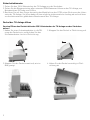
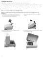
1. Haken Sie einen Schraubendreher in die Öff-
nung des Deckels ein und drücken Sie den
Schraubendreher leicht in Pfeilrichtung.
Vor dem Öffnen des Deckels bitte den 230 V-Netzstecker der TK-Anlage aus der Steckdose
ziehen!
2. Klappen Sie den Deckel in Pfeilrichtung auf.
4. Heben Sie den Deckel vorsichtig in Pfeil-
richtung ab.
Sicherheitshinweise
Deckel der TK-Anlage öffnen
3. Klappen Sie den Deckel soweit auf, wie im
Bild gezeigt.
2

Deckel der TK-Anlage schließen
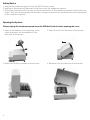
- Modul senkrecht, große Steckerleiste nach oben, in den oberen und unteren Führungs-
schlitz eines Steckplatzes einsetzen.
- Schieben Sie das Modul vorsichtig nach hinten bis die Steckverbinder greifen.
- Kleben Sie den entsprechenden Aufkleber, auf dem die Anschlüsse des Moduls darge-
stellt sind, über dem Steckplatz des Moduls auf das Gehäuse.
Hinweise zur Beschaltung des vorliegenden Moduls entnehmen Sie bitte dem Aufkleber
oder der Installationsanleitung AS 43, AS 45 (IdentNr. 1100835).
1. Schließen Sie alle zuvor getrennten ISDN-Basisanschlüsse wieder an.
2. Haken Sie die gebogene Nase des Deckels vorsichtig in die dafür vorgesehene Aufnahme.
3. Drehen Sie den Deckel so, das die gerade Nase in die dafür vorgesehene Aufnahme paßt.
4. Schließen Sie den Deckel mit sanftem Druck, bis die Rastnase hörbar einrastet.
Einbau des Moduls
TK-Anlage in Betrieb nehmen
Vor der Inbetriebnahme der TK-Anlage muß der Deckel der TK-Anlage geschlossen sein!
Nachdem der Deckel geschlossen ist, stecken Sie den Netzstecker der TK-Anlage wieder
ein.
Modul aus der Verpackung nehmen
Bevor Sie das Modul aus der Verpackung nehmen und bevor Sie das Modul in die TK-Anlage
einstecken, berühren Sie mit dem Finger kurzzeitig den Metallschirm der PC/Drucker-
Buchse an der Unterseite der TK-Anlage. Sie leiten dadurch eine mögliche elektrostatische
Ladung ab und schützen so die elektrostatisch gefährdeten Bauelemente der TK-Anlage
und des Moduls.
D
3

1. Unplug the telephone system from the 230 V mains socket.
2. Unplug or disconnect all external trunk lines from the telephone system.
3. Touch the metal of the PC/ printer socket at the bottom of the telephone system briefly with your
finger. This will discharge any electrostatic charges to protect the sensitive electronic equipment
of the telephone system.
1. Insert a screwdriver in the opening of the
cover and press the screwdriver in the
direction of the arrow.
Please unplug the telephone system from the 230 Main Socket before opening the cover.
2. Open the lid in the direction of the arrow.
4. Remove lid in the direction of the arrow.
Saftey Notice
Opening the System
3. Open the lid fully as shown in the picture.
4

Closing the Cover
- Slot the module vertically into guide rails the expansion slot with the large connection
strip facing upwards.
- Push the module as far as it will go into the slot so that the connection strip will make
contact with the motherboard.
- Stick the relevant module sticker displaying the connection diagram above the expansion
slot of the system.
Information regarding contact assignment of the installed module refer to the sticker or
installation manual AS 43, AS 45 (IdentNr. 1101332).
1. Reconnect all trunk lines disconnected previously.
2. Insert the curved hook of the lid carefully into the slots provided.
3. Turn the lid in such a way that the straight hook will fit into the designated slot.
4. Close the lid by pressing it into position until you hear a click.
Module Installation
System Power Up
Ensure that the lid of the telephone system is closed before operation.
Once the lid has been fitted, plug the system back to the 230 V mains socket.
Removing the Module from the Packaging
Before removing the module from the packaging touch the metal of the PC/ printer socket
on the bottom of the telephone system briefly with your finger. This will discharge any
electrostatic charges to protect the sensitive electronic equipment of the telephone system.
GB
5

1.Retirez de la prise murale la fiche 230 V du central téléphonique.
2. Débranchez les connecteurs modulaires de toutes les connexions de base RNIS externes sur le
central téléphonique, au niveau de la terminaison du réseau (NT) ou sur le bus S0.
3.Touchez brièvement du doigt l’écran métallique de la douille pour PC/imprimante située sur le
côté inférieur du central. Ceci vous permet d’éliminer une charge électrostatique éventuelle et
de protéger ainsi les composants du central que cette charge électrostatique peut
endommager.
1.Introduisez un tournevis dans l’ouverture
du couvercle et poussez légèrement sur le
tournevis dans le sens de la flèche.
Retirez le connecteur 230 V du central téléphonique de la prise murale avec d’ouvrir le
couvercle !
2. Ouvrez le couvercle dans le sens de la
flèche.
4.Soulevez le couvercle avec précaution dans
le sens de la flèche.
Consignes de sécurité
Ouvrir le couvercle du central téléphonique.
3. Ouvrez le couvercle en le rabattant aussi
loin que sur la figure.
6

Fermer le couvercle du central téléphonique
- Placez le module à la verticale, la grande barrette de connecteurs orientée vers le haut,
dans la fente supérieure et inférieure d’un emplacement dédié.
- Faites glisser avec précaution le module vers l’arrière jusqu’à ce que les connecteurs à
fiche entrent en prise.
- Collez l’autocollant correspondant qui représente les connexions du module au-dessus
de l’emplacement du module, sur le boîtier.
Vous trouverez des consignes relatives aux connexions de ce module sur l’autocollant ou
dans la notice d’utilisation AS 43, AS 454 (référence 1101332).
1. Rétablissez toutes les connexions de base RNIS qui avaient été débranchées.
2.Accrochez avec précaution le taquet courbé du couvercle dans le logement prévu à cet
effet.
3. Pivotez le couvercle de telle sorte que le taquet non courbé entre dans le logement
prévu à cet effet.
4. Fermez le couvercle par une légère pression jusqu’à ce que vous entendiez le taquet
entrer en prise.
Monter le module
Mise en service du central téléphonique
Avant la mise en service du central téléphonique, le couvercle du central doit être fermé !
Après avoir fermé le couvercle, rebranchez la prise secteur du central téléphonique.
Déballer le module.
Avant de prendre le module pour le sortir de son emballage et avant de l’enficher dans le
central téléphonique, touchez brièvement du doigt l’écran métallique de la douille pour
PC/imprimante située sur le côté inférieur du central. Ceci vous permet d’éliminer une
charge électrostatique éventuelle et de protéger les composants du central et du module
que cette charge électrostatique peut endommager.
F
7

Identnr. 1100663
Änderung und Irrtum vorbehalten.
Printed in Germany
0071
AGFEO GmbH & Co. KG
Gaswerkstr. 8
D-33647 Bielefeld
Internet: http://www.agfeo.de
La poubelle barrée reproduite sur un produit signifie que le produit appartient à la
catégorie des appareils électriques et électroniques. Dans ce contexte, et
conformément à la réglementation européenne, vous êtes tenu d'amener
vos appareils usagés
- aux points de vente si vous achetez un appareil similaire
- aux points de collecte locaux à votre disposition (déchetterie, point
recyclage etc.).
Vous participez ainsi au recyclage et à la valorisation des appareils électriques
et électroniques qui pourraient sinon avoir des répercussions négatives sur
l'environnement et la santé des humains.
Die auf dem Produkt angebrachte durchkreuzte Mülltonne bedeutet, dass das Produkt zur
Gruppe der Elektro- und Elektronikgeräte gehört. In diesem Zusammenhang weist die
europäische Regelung Sie an, Ihre gebrauchten Geräte
- den Verkaufsstellen im Falle des Kaufs eines gleichwertigen Geräts
- den örtlich Ihnen zur Verfügung gestellten Sammelstellen (Wertstoffhof,
Sortierte Sammlung usw.)
zuzuführen.
So beteiligen Sie sich an der Wiederverwendung und der Valorisierung von Elektrik- und
Elektronik-Altgeräten, die andernfalls negative Auswirkungen auf die Umwelt und die
menschliche Gesundheit haben könnten.
The crossed out wheeled bin on the product means that this belongs to the group of
Electro- and electronic apparatus.
In this context you are directed by the European regulation to dispose of used apparatus
- at the point of buying an item of equal proportion / value
- at the local available collection point for disposal
With this you will participate in the reuse of material and valorisation of disused electric-
and electronic apparatus, which otherwise could be a health hazard and be negative to the
environment.
-
 1
1
-
 2
2
-
 3
3
-
 4
4
-
 5
5
-
 6
6
-
 7
7
-
 8
8


AGFEO AS 43 Installationsanleitung
- Typ
- Installationsanleitung
- Dieses Handbuch eignet sich auch für
in anderen Sprachen
- English: AGFEO AS 43 Installation guide
- français: AGFEO AS 43 Guide d'installation
Verwandte Artikel
-
AGFEO AS 45 Installationsanleitung
-
AGFEO AS 40 - Modul Installationsanleitung
-
-
-
-
AGFEO AS 35 All-In-One Quick Manual
-
-
-
AGFEO BT-Modul 40 Bedienungsanleitung