
CEBORA S.p.A. 1
3300305-B 18-03-2016
I
MANUALE DI ISTRUZIONE PER GENERATORI Artt. 387 E 389 IN
APPLICAZIONI ROBOT.
pag. 2
GB
INSTRUCTIONS MANUAL FOR POWER SOURCES Arts. 387 AND
389 IN ROBOT APPLICATIONS.
page 11
E
MANUAL DE ISTRUCCIONES PARA GENERADORES Artt. 387 Y
389 EN APPLICACIONES ROBOT.
pag. 20
D
BETRIEBSANLEITUNG FÜR DIE STROMQUELLEN Art. 387 UND
389 IN ROBOTERANWENDUNGEN.
seite 29
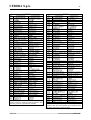
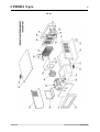
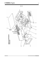
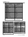
Parti di ricambio e schemi elettrici.
Spare parts and wiring diagrams. page 39
Piezas de repuesto y esquemas electricos.
Ersatzteile und Schaltpläne.

CEBORA S.p.A. 2
3300305-B 18-03-2016
I
IMPORTANTE: PRIMA DELLA MESSA IN
OPERA DELL'APPARECCHIO LEGGERE IL
CONTENUTO DI QUESTO MANUALE E
CONSERVARLO, PER TUTTA LA VITA
OPERATIVA, IN UN LUOGO NOTO AGLI
INTERESSATI. QUESTO APPARECCHIO
DEVE ESSERE UTILIZZATO
ESCLUSIVAMENTE PER OPERAZIONI DI
SALDATURA.
1 PRECAUZIONI DI SICUREZZA.
LA SALDATURA ED IL TAGLIO AD ARCO
POSSONO ESSERE
NOCIVI PER VOI E PER
GLI ALTRI, pertanto
l'utilizzatore deve essere istruito contro i rischi, di
seguito riassunti, derivanti dalle operazioni di
saldatura. Per informazioni più dettagliate
richiedere il manuale cod. 3.300.758.
RUMORE.
Questo apparecchio non produce di per
se rumori eccedenti gli 80dB. Il
procedimento di taglio
plasma/saldatura può produrre livelli di rumore
superiori a tale limite; pertanto, gli utilizzatori
dovranno mettere in atto le precauzioni previste
dalla legge.
CAMPI ELETTROMAGNETICI. Possono
essere dannosi. La corrente
elettrica che attraversa qualsiasi
conduttore produce dei campi
elettromagnetici (EMF). La
corrente di saldatura o di taglio
genera campi elettromagnetici attorno ai cavi ed
ai generatori.
I campi magnetici derivanti da correnti elevate
possono incidere sul funzionamento di
pacemaker.
I portatori di apparecchiature elettroniche vitali
(pacemaker) devono consultare il medico prima
di avvicinarsi alle operazioni di saldatura ad arco,
di taglio, scriccatura o di saldatura a punti.
L’ esposizione ai campi elettromagnetici della
saldatura o del taglio potrebbe avere effetti
sconosciuti sulla salute. Ogni operatore, per
ridurre i rischi derivanti dall’ esposizione ai
campi elettromagnetici, deve attenersi alle
seguenti procedure:
- Fare in modo che il cavo di massa e della
pinza portaelettrodo o della torcia rimangano
affiancati. Se possibile, fissarli assieme con
del nastro.
- Non avvolgere i cavi di massa e della pinza
porta elettrodo o della torcia attorno al corpo.
- Non stare mai tra il cavo di massa e quello
della pinza portaelettrodo o della torcia. Se il
cavo di massa si trova sulla destra
dell’operatore anche quello della pinza
portaelettrodo o della torcia deve stare da
quella parte.
- Collegare il cavo di massa al pezzo in
lavorazione più vicino possibile alla zona di
saldatura o di taglio.
- Non lavorare vicino al generatore.
ESPLOSIONI.
Non saldare in prossimità di recipienti
a pressione o in presenza di polveri, gas
o vapori esplosivi.
Maneggiare con cura bombole e regolatori di
pressione utilizzati nelle operazioni di saldatura.
COMPATIBILITÀ ELETTROMAGNETICA.
Questo apparecchio è costruito in conformità alle
indicazioni contenute nella norma IEC 60974-
10(Cl. A) e deve essere usato solo a scopo
professionale in un ambiente industriale. Vi
possono essere, infatti, potenziali difficoltà
nell'assicurare la compatibilità
elettromagnetica in un ambiente diverso da
quello industriale.
SMALTIMENTO APPARECCHIATURE
ELETTRICHE ED ELETTRONICHE.
Non smaltire le apparecchiature
elettriche assieme ai rifiuti normali!
In ottemperanza alla Direttiva Europea
2002/96/CE sui rifiuti da apparecchiature
elettriche ed elettroniche e relativa attuazione
nell'ambito della legislazione nazionale, le
apparecchiature elettriche giunte a fine vita
devono essere raccolte separatamente e conferite
ad un impianto di riciclo ecocompatibile. In
qualità di proprietario delle apparecchiature
dovrà informarsi presso il nostro rappresentante
in loco sui sistemi di raccolta approvati. Dando
applicazione a questa Direttiva Europea
migliorerà la situazione ambientale e la salute
umana!
IN CASO DI CATTIVO FUNZIONAMENTO
RICHIEDETE L’ASSISTENZA DI
PERSONALE QUALIFICATO.

CEBORA S.p.A. 3
3300305-B 18-03-2016
I
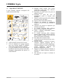
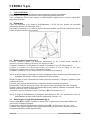
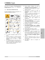
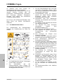
1.1 Targa delle AVVERTENZE.
Il testo numerato seguente corrisponde alle
caselle numerate della targa.
B. I rullini trainafilo possono ferire le mani.
C. Il filo di saldatura ed il gruppo trainafilo
sono sotto tensione durante la saldatura.
Tenere mani eoggetti metallici a distanza.
1. Le scosse elettriche provocate dall’elettrodo
di saldatura o dal cavo possono essere letali.
Proteggersi adeguatamente dal pericolo di
scosse elettriche.
1.1 Indossare guanti isolanti. Non toccare
l’elettrodo a mani nude. Non indossare
guanti umidi o danneggiati.
1.2 Assicurarsi di essere isolati dal pezzo da
saldare e dal suolo.
1.3 Scollegare la spina del cavo di
alimentazione prima di lavorare sulla
macchina.
2. Inalare le esalazioni prodotte dalla saldatura
può essere nocivo alla salute.
2.1 Tenere la testa lontana dalle esalazioni.
2.2 Utilizzare un impianto di ventilazione
forzata o di scarico locale per eliminare le
esalazioni.
2.3 Utilizzare una ventola di aspirazione per
eliminare le esalazioni.
3. Le scintille provocate dalla saldatura
possono causare esplosioni od incendi.
3.1 Tenere i materiali infiammabili lontano
dall’area di saldatura.
3.2 Le scintille provocate dalla saldatura
possono causare incendi Tenere un estintore
nelle immediate vicinanze e far sì che una
persona resti pronta ad utilizzarlo.
3.3 Non saldare mai contenitori chiusi.
4. I raggi dell’arco possono bruciare gli occhi e
ustionare la pelle.
4.1 Indossare elmetto e occhiali di sicurezza.
Utilizzare adeguate protezioni per le
orecchie e camici con il colletto abbottonato.
Utilizzare maschere a casco con filtri della
corretta gradazione. Indossare una
protezione completa per il corpo.
5. Leggere le istruzioni prima di utilizzare la
macchina od eseguire qualsiasi operazione
su di essa.
6. Non rimuovere né coprire le etichette di
avvertenza.

CEBORA S.p.A. 4
3300305-B 18-03-2016
I
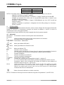
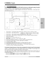
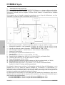
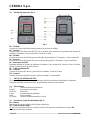
2 DESCRIZIONE SISTEMA.
Il Sistema di Saldatura SOUND MIG ROBOT PULSE Cebora è un sistema multiprocesso idoneo alla
saldatura MIG/MAG pulsato sinergico, MIG/MAG non pulsato sinergico, MIG/MAG convenzionale,
realizzato per essere abbinato ad un braccio Robot Saldante, su impianti di saldatura automatizzati.
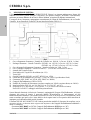
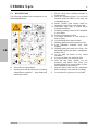
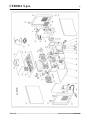
È composto da un Generatore, equipaggiato eventualmente di Gruppo di Raffreddamento, da un Carrello
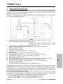
Trainafilo, da un Pannello di Controllo e da una Interfaccia Robot (vedi fig. 1).
fig. 1
1 Cavo collegamento Generatore - Pannello di Controllo (art. 1199.00, l = 5m; art. 1199.20, l = 10m).
2 Prolunga Generatore – Carrello Trainafilo (WF4-R1 : art. 1197.00, l = 5m; art. 1197.20, l = 10m).
(WF4-R2 : art. 1173.00, l = 5m; art. 1173.20, l = 10m).
3 Cavo dei segnali collegamento Generatore – Interfaccia Robot (art. 1200, l = 5m).
4 Cavo CANopen Generatore – Interfaccia Robot (l = 1,5 m incluso nell’Interfaccia Robot).
5 Armadio del Controllo Robot.
6 Porta bobina da 15 kg del filo di saldatura (art. 121).
7 Torcia MIG.
8 Carrello Trainafilo (WF4-R1, art. 1657; WF4-R2, art. 1658).
10 Guaina del filo di saldatura (art. 1935.00, l = 1,6 m; art. 1935.01, per Marathon Pack).
21 Generatore (MIG 3840/T art. 387.80; MIG 5040/T art. 389.80).
22 Gruppo di Raffreddamento (GR54 o GR52).
24 Pannello di Controllo del Generatore (versione completa, art. 208.00; versione ridotta, art. 208.10).
25 Interfaccia Robot (RDI 210, art. 210; RAI 211, art. 211; RAI 217, art. 217).
26 Per RDI210: cavo “DeviceNet”, (cod. 5585987, l = 2 m, incluso nell’Interfaccia Robot).
Per RAI211 e RAI217: cablaggio multifilare personalizzato.
Questo Manuale Istruzioni si riferisce ai Generatori, equipaggiati di Gruppo di Raffreddamento, ed è stato
preparato allo scopo di istruire il personale addetto all'installazione, al funzionamento ed alla
manutenzione della saldatrice. Deve essere conservato con cura, in un luogo noto ai vari interessati, dovrà
essere consultato ogni qual volta vi siano dubbi e dovrà seguire tutta la vita operativa della macchina ed
impiegato per l'ordinazione delle parti di ricambio.
Il sistema SOUND MIG ROBOT PULSE Cebora prevede due modelli di Generatori da scegliere, uno in
alternativa all’altro, in funzione delle esigenze dell’impianto e due Gruppi di Raffreddamento abbinabili o
meno ai Generatori:
Generatore MIG 3840/T art. 387.80. Gruppo di Raffreddamento GR54 (per art. 387).
Generatore MIG 5040/T art. 389.80. Gruppo di Raffreddamento GR52 (per art. 389).

CEBORA S.p.A. 5
3300305-B 18-03-2016
I
3 INSTALLAZIONE.
Questo apparecchio deve essere utilizzato esclusivamente per operazioni di saldatura.
L'installazione delle apparecchiature deve essere eseguita da personale qualificato.
Tutti i collegamenti devono essere eseguiti in conformità delle vigenti norme e nel pieno rispetto della
legge antinfortunistica.
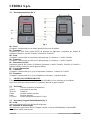
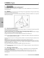
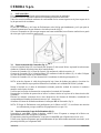
3.1 Sistemazione.
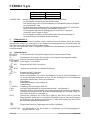
Il peso del Generatore e del Gruppo di Raffreddamento è di 100 Kg circa, pertanto per l'eventuale
sollevamento attenersi alle indicazioni di fig. 2.
Posizionare il Generatore in una zona che assicuri una buona stabilità, un'efficiente ventilazione e tale da
evitare che polvere metallica possa entrare.
fig. 2
3.2 Messa in opera Generatore (fig. 1).
Collocare l’Interfaccia Robot (25) all’interno dell’Armadio (5) del controllo Robot, seguendo le
indicazioni riportate nel Manuale Istruzioni dell’Interfaccia Robot.
Collegare il Generatore (21) al Pannello di Controllo (24) mediante il cavo di collegamento (1).
Collegare il Generatore (21) all’Interfaccia Robot (25) mediante il cavo dei segnali (3) ed il cavo
CANopen (4) (questo ultimo è incluso nell’Interfaccia Robot).
Collegare il Generatore (21) al Carrello Trainafilo (8) mediante la prolunga (2).
NOTA: evitare di disporre la prolunga sotto forma di bobina per ridurre al minimo gli effetti induttivi che
potrebbero influenzare il risultati in saldatura MIG/MAG pulsato.
Montare la spina sul cavo d'alimentazione facendo particolare attenzione a collegare il conduttore giallo
verde al polo di terra.
Verificare che la tensione d'alimentazione corrisponda a quella nominale del Generatore.
Dimensionare i fusibili di protezione in base ai dati riportati sulla targa dei dati tecnici del Generatore.
Eseguire i restanti collegamenti delle altre apparecchiature del Sistema di Saldatura, consultando i relativi
Manuali di Istruzioni al par. “Installazione”.
Alimentare il Sistema di Saldatura tramite l’interruttore BU del Generatore (fig. 3).
NOTA: Il Gruppo di Raffreddamento è predisposto dalla fabbrica su OFF. Se è utilizzata una torcia con
raffreddamento ad acqua, modificare tale impostazione (vedi par. 6.4).
3.3 Messa in opera Gruppo di Raffreddamento (fig 3).
Svitare il tappo BW e riempire il serbatoio, capienza 5 litri. L'apparecchio è fornito dalla fabbrica con
circa un litro di liquido già presente.
E' importante controllare periodicamente, attraverso l'asola BX, che il liquido sia al livello “max”.
Utilizzare come liquido refrigerante acqua (preferibilmente del tipo deionizzato) miscelata con alcool,
nella percentuale definita dalla seguente tabella:

CEBORA S.p.A. 6
3300305-B 18-03-2016
I
temperatura
acqua/alcool.
0°C fino a -5°C
4L/1L
-5°C fino a -10°C
3,8L/1,2L
NOTA: Se la pompa ruota in assenza del liquido refrigerante è necessario togliere l'aria dai tubi:
- spegnere il Generatore e riempire il serbatoio;
- scollegare il tubo blu della prolunga (2) Generatore - Carrello Trainafilo dal raccordo BT;
- collegare una estremità di un nuovo tubo al raccordo BT rimasto libero e inserire l’altra
estremità del tubo nel serbatoio;
- accendere il Generatore e quindi il Gruppo di Raffreddamento per circa 10/15 secondi per
riempire la pompa;
- spegnere il Generatore e ripristinare i collegamenti dei tubi della prolunga (2) Generatore -
Carrello Trainafilo.
4 GENERATORE.
Il Generatore non ha un funzionamento autonomo, ma deve essere collegato alle altre apparecchiature del
Sistema. Il Generatore è l’alimentatore principale del Sistema di Saldatura e fornisce le tensioni di
alimentazione a tutte le altre apparecchiature.
L'apparecchio può essere utilizzato solo per gli impieghi descritti nel presente manuale.
4.1 Dati tecnici.
IEC 60974.1 Il Generatore è costruito secondo queste norme internazionali.
EN 50199
N°. Numero di matricola da citare per ogni richiesta relativa al Generatore.
Convertitore statico di frequenza trifase.
Trasformatore - raddrizzatore.
MIG Adatto per saldatura MIG/MAG.
MMA Adatto per saldatura con elettrodi rivestiti.
TIG Adatto per saldatura TIG.
U0. Tensione a vuoto secondaria.
X. Fattore di servizio percentuale. Il fattore di servizio esprime la percentuale di 10 minuti in
cui il Generatore può lavorare ad una determinata corrente senza surriscaldarsi.
I2. Corrente di saldatura.
U2. Tensione secondaria con corrente I2.
U1. Tensione nominale di alimentazione.
3~ 50/60Hz Alimentazione trifase 50 / 60 Hz.
I
1
Max Corrente max. assorbita alla corrispondente corrente I
2
e tensione U
2
.
I
1
eff E’ il valore massimo della corrente effettiva assorbita considerando il fattore i servizio.
Solitamente, questo valore corrisponde alla portata del fusibile (di tipo ritardato) da
utilizzare come protezione per l’ apparecchio.
IP23 C Grado di protezione della carcassa. Grado 3 come seconda cifra significa che questo
apparecchio è idoneo a lavorare all’esterno sotto la pioggia. La lettera addizionale C
significa che l’apparecchio è protetto contro l’accesso di un utensile (Ø 2,5 mm) alle parti
in tensione del circuito di alimentazione.
Idoneo a lavorare in ambienti con rischio accresciuto.
NOTA: Il Generatore è idoneo per lavorare in ambienti con grado di inquinamento 3 (vedi IEC 664).

CEBORA S.p.A. 7
3300305-B 18-03-2016
I
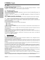
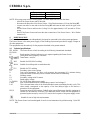
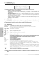
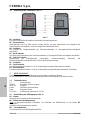
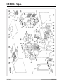
4.2 Descrizione generatore (fig. 3).
fig. 3
BO - Presa.
Collegare il connettore del cavo di massa (potenziale del pezzo da saldare).
BP - Connettore.
Connettore tipo DB9 (linea seriale RS232) da utilizzare per aggiornare i programmi del Sistema di
Saldatura (Generatore, Carrello Trainafilo e Pannello di Controllo).
BR - Presa.
Collegare il connettore del cavo di potenza della prolunga (2) Generatore - Carrello Trainafilo.
BS - Connettore.
Collegare il connettore del cavo dei servizi della prolunga (2) Generatore - Carrello Trainafilo.
BU - Interruttore ON/OFF.
Interruttore generale del Sistema di Saldatura (Generatore, Carrello Trainafilo, Pannello di Controllo e
Interfaccia Robot) (esclusa la parte di gestione Robot).
BV - Cavo di alimentazione.
BY - Connettore.
Collegare il connettore del cavo (1) per collegamento Generatore – Pannello di Controllo.
BZ - Connettore.
Collegare il connettore del cavo (3) per collegamento Generatore – Interfaccia Robot.
5 GRUPPO DI RAFFREDDAMENTO.
Il Gruppo di Raffreddamento è stato progettato per raffreddare le torce utilizzate per la saldatura.
Deve essere utilizzato esclusivamente con i generatori descritti in questo manuale.
5.1 Dati tecnici.
U1 Tensione nominale di alimentazione.
1x400V Alimentazione monofase.
50/60 Hz Frequenza.
I1max Corrente massima assorbita.
Pmax Pressione massima.
P (1l/min) Potenza refrigerante misurata a 1L/min.
5.2 Descrizione Gruppo di Raffreddamento (fig. 3).
BX - Asola.
Asola per l'ispezione del livello del liquido refrigerante.
BQ - Rubinetti ad innesto rapido.
Non utilizzare in applicazioni Robot. Collegare i tubi del circuito di raffreddamento ai rubinetti BT.
Non debbono essere cortocircuitati.

CEBORA S.p.A. 8
3300305-B 18-03-2016
I
BW - Tappo.
Tappo del serbatoio del liquido di raffreddamento.
BT - Rubinetti ad innesto rapido.
Collegare i tubi segnalati con la fascetta adesiva rossa e blu della prolunga Generatore - Carrello
Trainafilo (2). Fare corrispondere i colori dei tubi con quelli dei rubinetti.
5.3 Descrizione protezioni.
5.3.1 Pressione liquido refrigerante.
Questa protezione è realizzata mediante un pressostato, inserito nel circuito di mandata della pompa, che
comanda un microinterruttore.
La pressione insufficiente è segnalata, con la sigla H2O lampeggiante sul display O del Pannello di
Controllo.
5.3.2 Fusibile (T 1,6A/400V - Ø 6,3x32 mm).
Questo fusibile è inserito a protezione della pompa ed è collocato sul pannello posteriore del Generatore.
5.4 Gestione Gruppo di Raffreddamento (vedi Manuale Istruzioni del Pannello di Controllo).
Su Pannello di Controllo premere il pulsante AO e, mantenendolo premuto, premere il pulsante E per
entrare in un sottomenu.
Con la manopola N eseguire la scelta: H2O.
Ruotare la manopola Q per selezionare il tipo di funzionamento:
OFF = spento;
OnC = sempre acceso;
OnA = accensione automatica.
Premere nuovamente i tasti AO ed E per uscire dal sottomenu, memorizzando automaticamente tutte le
impostazioni attuali.
All’accensione del Generatore, il Gruppo entra in funzione per mettere in pressione il liquido nel circuito
di raffreddamento.
Se entro 15 secondi non arriva il comando di start (segnale ARC-ON) il gruppo si arresta.
Ad ogni comando di start (segnale ARC-ON) il Gruppo inizia a funzionare e si arresta 3 minuti dopo la
scomparsa del segnale di start.
Se la pressione del liquido refrigerante è insufficiente il Generatore non eroga corrente e sul display O
compare la scritta H2O lampeggiante.
6 MANUTENZIONE.
6.1 Ispezione periodica, pulizia.
Periodicamente controllare che le apparecchiature del Sistema di Saldatura e tutti i collegamenti siano in
condizione di garantire la sicurezza dell'operatore.
Periodicamente aprire i pannelli del Generatore per controllare gli elementi interni. Rimuovere eventuale
sporco o polvere dagli elementi interni, utilizzando un getto d’aria compressa secca a bassa pressione o un
pennello.
Controllare le condizioni delle connessioni interne di potenza e dei connettori sulle schede elettroniche; se
si trovano connessioni “lente” serrarle o sostituire i connettori.
Per assicurare un corretto flusso d’aria e quindi l’adeguato raffreddamento degli elementi interni del
Generatore, periodicamente aprire le griglie sul Generatore e controllare l’interno del tunnel d’aerazione.
Rimuovere l’eventuale sporco o polvere dagli elementi interni del Tunnel, utilizzando un getto d’aria
compressa secca a bassa pressione o un pennello.
Controllare le condizioni dei connettori elettrici, del cavo di alimentazione e degli attacchi pneumatici; se
danneggiati sostituirli.
Dopo aver eseguito una riparazione fare attenzione a riordinare il cablaggio in modo che vi sia un sicuro
isolamento tra le parti connesse all'alimentazione e le parti connesse al circuito di saldatura.
Evitare che i fili possano andare a contatto con parti in movimento o con parti che si riscaldano durante il
funzionamento.
Rimontare le fascette come erano in origine in modo da evitare che, se accidentalmente un conduttore si
rompe o si scollega, possa avvenire un collegamento tra alimentazione ed i circuiti di saldatura.

CEBORA S.p.A. 9
3300305-B 18-03-2016
I
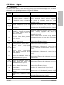
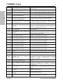
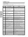
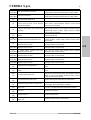
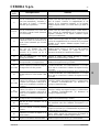
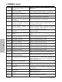
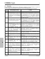
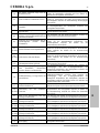
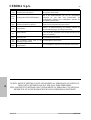
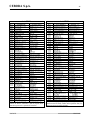
6.2 Codici Errore.
La tabella seguente indica i “Codici Errore” che possono essere visualizzati sui display O e P del Pannello
di Controllo in caso di malfunzionamento del Sistema di Saldatura.
Per una descrizione più dettagliata sulla ricerca guasti consultare il Manuale di Servizio del Generatore.
Codici
Errore
Descrizione Errore
Soluzione
2
Errore EEPROM.
Sostituire scheda Controllo.
6
Errore di comunicazione sul CAN bus
fra Carrello Trainafilo e Generatore, o
fra Pannello di Controllo e Generatore
(rilevato da Generatore).
Allarme rilevato dalla scheda Controllo. Controllare il
collegamento CAN bus fra schede Controllo, Controllo
Motore e Pannello di Controllo. Verificare compatibilità
delle versioni dei programmi inseriti nelle schede.
Sostituire schede Controllo e/o Controllo Motore e/o
Pannello di Controllo.
“rob int”
7
Errore di comunicazione sul CAN bus
fra Robot e scheda Controllo (rilevato
da Generatore).
Allarme rilevato dalla scheda Controllo. Controllare il
collegamento CAN bus fra schede Controllo, Controllo
Motore e Robot. Verificare compatibilità delle versioni dei
programmi inseriti nelle schede. Sostituire schede Controllo
e/o Controllo Motore.
9
Errore di comunicazione sul CAN bus.
Il Pannello di Controllo non comunica
con la scheda Controllo (rilevato da
Pannello di Controllo).
Allarme rilevato dal Pannello di Controllo. Controllare il
collegamento CAN bus fra Pannello di Controllo e scheda
Controllo. Verificare compatibilità delle versioni dei
programmi inseriti nelle schede. Sostituire scheda Controllo
e/o Pannello di Controllo.
10
Tensione d’uscita e corrente d’uscita
nulle, con pulsante di start premuto.
Errore nei circuiti di rilievo tensione o
corrente d’uscita.
Sostituire schede Controllo e/o Driver e/o Igbt. Sostituire
Trasformatore di potenza e/o Gruppo Diodi e/o Induttanza
d’uscita e/o Trasduttore di corrente.
13
Mancanza comunicazione con scheda
Precarica, all’accensione.
Controllare cablaggio fra schede Precarica e Controllo.
Sostituire schede Precarica e Controllo.
14
Errore della tensione di alimentazione
del Microprocessore, su scheda Micro.
Controllare cablaggio fra schede Micro e Flyback.
Sostituire schede Controllo e/o Flyback.
15
(solo 389)
Tensione continua all’uscita della
scheda Precarica inferiore al valore
previsto.
Controllare condizioni della tensione di rete. Verificare che
Ponte Raddrizzatore, Condensatori-DC o Gruppo Igbt non
siano in cortocircuito. Sostituire schede Precarica e/o
Controllo.
16
Tensione continua all’uscita della
scheda Precarica inferiore al valore
minimo (400 Vdc).
Controllare condizioni della tensione di rete. Verificare che
Ponte Raddrizzatore, Condensatori-DC o Gruppo Igbt non
siano in cortocircuito. Sostituire schede Precarica e/o
Controllo.
17
(solo 389)
Errore ripartizione tensione continua.
Tensione sul condensatore connesso al
negativo maggiore della tensione sul
condensatore connesso al positivo.
Controllare cablaggio fra scheda Precarica e Condensatori-
DC. Sostituire Condensatori-DC e/o Resistori di scarica e/o
scheda Precarica.
18
(solo 389)
Errore ripartizione tensione continua.
Tensione sul condensatore connesso al
negativo minore della tensione sul
condensatore connesso al positivo.
Controllare cablaggio fra scheda Precarica e Condensatori-
DC. Sostituire Condensatori-DC e/o Resistori di scarica e/o
scheda Precarica.
19
(solo 389)
Mancanza comunicazione con scheda
Precarica, durante il funzionamento.
Controllare cablaggio fra schede Precarica e Controllo.
Sostituire schede Precarica e Controllo.
20
Mancanza segnale “interlock” su
modulo Master.
Controllare che i terminali 3 e 4 di J1 su scheda TA siano
connessi fra loro. Sostituire schede TA e/o Controllo.
25
Errore nella EPLD. Corrente al primario
eccessiva.
Sostituire schede Controllo e/o Driver e/o TA. Sostituire gli
Igbt dell’inverter e/o Trasformatore di potenza e/o Gruppo
Diodi secondario.
30
Taratura errata del trimmer su modulo
master.
Eseguire la procedura di taratura del trimmer su scheda
Controllo, seguendo le istruzioni del Manuale di Servizio
del Generatore. Sostituire scheda Controllo.
41
Scheda Connettore/Robot scollegata.
Sostituire schede Controllo Motore e/o Connettore.

CEBORA S.p.A. 10
3300305-B 18-03-2016
I
42
Errore Encoder (eccessiva differenza fra
velocità di riferimento e misurata).
Sostituire Encoder o Motore Trainafilo e/o scheda
Controllo Motore.
43
Errore di comunicazione con scheda
Connettore (seriale UART).
Controllare flat-cable fra schede Connettore e Controllo
Motore. Sostituire schede Connettore e/o Controllo Motore.
45
(solo 389)
Scheda Push-pull non connessa.
Controllare cablaggio fra schede Push-pull e Controllo
Motore. Sostituire schede Push-pull e/o Controllo Motore.
46
(solo 389)
Errore su scheda Push-pull.
Controllare cablaggio fra schede Push-pull e Controllo
Motore. Sostituire schede Push-pull e/o Controllo Motore.
“trG”
(53)
Pulsante di Start premuto al ripristino da
allarme per sovratemperatura.
Sostituire schede Connettore e/o Controllo Motore.
54
Presenza di corrente in uscita
Generatore all’accensione (cortocircuito
fra torcia e pezzo).
Controllare il cablaggio di potenza fra uscita Gruppo Diodi
e terminali d’uscita del Generatore. Sostituire scheda
Controllo e/o Trasduttore di corrente.
56
Time-out max., durata del Cortocircuito
eccessiva.
Controllare condizioni di usura della torcia, cablaggio di
potenza fra uscita Gruppo Diodi e terminali d’uscita del
Generatore. Sostituire schede Misura e/o Controllo e/o
Driver-ac e/o Trasduttore di corrente.
“Mot”
(57)
Errore eccessivo nella corrente del
Motore trainafilo.
Sostituire Motore trainafilo o Gruppo trainafilo e/o scheda
Controllo Motore.
58
(solo 389)
Disallineamento delle versioni del
Firmware.
Riprogrammare il Generatore con il Firmware nelle
versioni corrette. Sostituire schede Controllo e/o Controllo
Motore e/o Pannello di Controllo.
61
Fase LI della tensione di rete inferiore al
valore minimo consentito.
Verificare il valore delle tre fasi della tensione di rete.
Sostituire schede Precarica e/o Controllo.
62
(solo 389)
Fase LI della tensione di rete superiore
al valore massimo consentito.
Verificare il valore delle tre fasi della tensione di rete.
Sostituire schede Precarica e/o Controllo.
63
(solo 389)
Fase L2 della tensione di rete inferiore
al valore minimo consentito.
Verificare il valore delle tre fasi della tensione di rete.
Sostituire schede Precarica e/o Controllo.
64
(solo 389)
Fase L2 della tensione di rete superiore
al valore massimo consentito.
Verificare il valore delle tre fasi della tensione di rete.
Sostituire schede Precarica e/o Controllo.
65
(solo 389)
Fase L3 della tensione di rete inferiore
al valore minimo consentito.
Verificare il valore delle tre fasi della tensione di rete.
Sostituire schede Precarica e/o Controllo.
66
(solo 389)
Fase L3 della tensione di rete superiore
al valore massimo consentito.
Verificare il valore delle tre fasi della tensione di rete.
Sostituire schede Precarica e/o Controllo.
“tH0”
(73)
Sovratemperatura Gruppo Diodi di
uscita.
Sostituire termostato su Gruppo Diodi e/o scheda Controllo.
“tH1”
(74)
Sovratemperatura Igbt Inverter (segnale
analogico).
Sostituire schede Termostato su Gruppo Igbt e/o Controllo.
“H2O”
(75)
Pressione bassa del liquido di
raffreddamento.
Controllare presenza del ponticello sui terminali 3 e 4 del
connettore J18 su scheda Controllo (solo 389). Sostituire
pressostato su Gruppo di raffreddamento e/o schede
Precarica e/o Controllo.
“OPn”
(80)
Carter Motore trainafilo aperto.
Sostituire microinterruttore del carter e/o scheda Controllo
Motore.
“rob”
(90)
Stop di emergenza da Robot, o Robot
spento.
Controllare collegamenti fra Generatore e Robot,
alimentazione del Robot e/o condizioni di sicurezza
dell’impianto.
“Sti”
(91)
Filo incollato.
Tagliare il filo o eseguire la procedura di “distacco
automatico del filo” (vedi Manuale Istruzioni Interfaccia
Robot).
“End”
(92)
Filo finito.
Sostituire la bobina del filo.
“Ito”
(98)
Arco non acceso entro il tempo
consentito.
Sostituire scheda Controllo.
“OFF”
(99)
Mancanza tensione di rete (Generatore
spento).
Sostituire schede Precarica e/o Controllo.

CEBORA S.p.A. 11
3300305-B 18-03-2016
GB
IMPORTANT: BEFORE STARTING THE
EQUIPMENT, READ THE CONTENTS OF
THIS MANUAL, WHICH MUST BE STORED
IN A PLACE FAMILIAR TO ALL USERS FOR
THE ENTIRE OPERATIVE LIFE-SPAN OF
THE MACHINE. THIS EQUIPMENT MUST
BE USED SOLELY FOR WELDING
OPERATIONS.
1 SAFETY PRECAUTIONS.
WELDING AND ARC CUTTING CAN BE
HARMFUL TO
YOURSELF AND
OTHERS.
The user must therefore be educated against the
hazards, summarized below, deriving from
welding operations. For more detailed
information, order the manual code 3.300.758.
NOISE.
This machine does not directly produce
noise exceeding 80dB. The plasma
cutting/welding procedure may produce
noise levels beyond said limit; users must
therefore implement all precautions required by
law.
ELECTRIC AND MAGNETIC FIELDS.
May be dangerous.
Electric current following through
any conductor causes localized
Electric and Magnetic Fields
(EMF).
Welding/cutting current creates EMF fields
around cables and power sources.
The magnetic fields created by high currents may
affect the operation of pacemakers. Wearers of
vital electronic equipment (pacemakers) shall
consult their physician before beginning any arc
welding, cutting, gouging or spot welding
operations.
Exposure to EMF fields in welding/cutting may
have other health effects which are now not
known.
All operators should use the following
procedures in order to minimize exposure to
EMF fields from the welding/cutting circuit:
- Route the electrode and work cables together
– Secure them with tape when possible.
- Never coil the electrode/torch lead around
your body.
- Do not place your body between the
electrode/torch lead and work cables. If the
electrode/torch lead cable is on your right
side, the work cable should also be on your
right side.
- Connect the work cable to the workpiece as
close as possible to the area being welded/cut.
- Do not work next to welding/cutting power
source.
EXPLOSIONS.
Do not weld in the vicinity of
containers under pressure, or in the
presence of explosive dust, gases or
fumes.
All cylinders and pressure regulators used in
welding operations should be handled with care.
ELECTROMAGNETIC COMPATIBILITY.
This machine is manufactured in compliance
with the instructions contained in the harmonized
standard IEC 60974-10 (CL.A), and must be
used solely for professional purposes in an
industrial environment. There may be
potential difficulties in ensuring
electromagnetic compatibility in non-
industrial environments.
DISPOSAL OF ELECTRICAL AND
ELECTRONIC EQUIPMENT.
Do not dispose of electrical equipment
together with normal waste!
In observance of European Directive
2002/96/EC on Waste Electrical and
Electronic Equipment and its implementation in
accordance with national law, electrical
equipment that has reached the end of its life
must be collected separately and returned to an
environmentally compatible recycling facility. As
the owner of the equipment, you should get
information on approved collection systems from
our local representative. By applying this
European Directive you will improve the
environment and human health!
IN CASE OF MALFUNCTIONS, REQUEST
ASSISTANCE FROM QUALIFIED
PERSONNEL

CEBORA S.p.A. 12
3300305-B 18-03-2016
GB
1.1 WARNING label.
The following numbered text corresponds to the
label numbered boxes.
B. Drive rolls can injure fingers.
C. Welding wire and drive parts are at welding
voltage during operation — keep hands and
metal objects away.
1. Electric shock from welding electrode or
wiring can kill.
1.1 Wear dry insulating gloves. Do not touch
electrode with bare hand. Do not wear wet
or damaged gloves.
1.2 Protect yourself from electric shock by
insulating yourself from work and ground.
1.3 Disconnect input plug or power before
working on machine.
2. Breathing welding fumes can be hazardous
to your health.
2.1 Keep your head out of fumes.
2.2 Use forced ventilation or local exhaust to
remove fumes.
2.3 Use ventilating fan to remove fumes.
3. Welding sparks can cause explosion or fire.
3.1 Keep flammable materials away from
welding.
3.2 Welding sparks can cause fires. Have a fire
extinguisher nearby and have a watchperson
ready to use it.
3.3 Do not weld on drums or any closed
containers.
4 Arc rays can burn eyes and injure skin.
4.1 Wear hat and safety glasses. Use ear
protection and button shirt collar. Use
welding helmet with correct shade of filter.
Wear complete body protection.
5 Become trained and read the instructions
before working on the machine or welding.
6 Do not remove or paint over (cover) label.

CEBORA S.p.A. 13
3300305-B 18-03-2016
GB
2 SYSTEM DESCRIPTION.
The Cebora SOUND MIG ROBOT PULSE Welding System is a multi-process system for pulsed
synergic MIG/MAG, non-pulsed synergic MIG/MAG, and conventional MIG/MAG welding, developed
for use in combination with a Welding Robot arm on automated welding systems.
It comprises a power source, possibly equipped with cooling unit, a wire feeder, a control panel and a
Robot Interface (see fig. 1).
fig. 1
1 Power Source – Control panel cable connection (art. 1199.00, l = 5m; art. 1199.20, l = 10m).
2 Power Source – Wire feeder extension (WF4-R1 : art. 1197.00, l = 5m; art. 1197.20, l = 10m).
(WF4-R2 : art. 1173.00, l = 5m; art. 1173.20, l = 10m).
3 Power Source – Robot Interface signal cable connection (art. 1200, l = 5m).
4 Power Source – Robot Interface CANopen cable (1.5 m long, included in the Robot Interface).
5 Robot control cabinet.
6 Welding wire 15 Kg spool holder (art. 121).
7 MIG Torch.
8 Wire Feeder unit (WF4-R1, art. 1657; WF4-R2, art. 1658).
10 Welding wire sheath (art. 1935.00, l = 1,6 m; art. 1935.01, per Marathon Pack).
21 Power Source (MIG 3840/T art. 387.80; MIG 5040/T art. 389.80).
22 Cooling unit (GR54 o GR52).
24 Power Source Control Panel (full version , art. 208.00; light version, 208.10).
25 Robot Interface (RDI 210, art. 210; RAI 211, art. 211; RAI 217, art. 217).
26 For RDI210: cable “DeviceNet”, (cod. 5585987, l = 2 m, included in Robot Interface).
For RAI211 e RAI217: dedicated multiwire wiring.
This Instruction Manual refers to the Power Source, equipped with Cooling Unit, and has been prepared
to educate the personnel assigned to install, operate and maintain the welding machine. It must be stored
carefully in a place familiar to users, and consulted whenever there are doubts. It must be kept for the
entire operative life-span of the machine, and used to order spare parts.
The Cebora SOUND MIG ROBOT PULSE system has two models of Power Source to choose from, one
or the other, based on system needs, and two Cooling Units that may or may not be used in combination
with the Power Sources:
Power source MIG 3840/T art. 387.80. Cooling Unit GR54 (for art. 387).
Power source MIG 5040/T art. 389.80. Cooling Unit GR52 (for art. 389).

CEBORA S.p.A. 14
3300305-B 18-03-2016
GB
3 INSTALLATION.
This equipment must be used solely for welding operations.
The equipment must be installed by qualified personnel.
All connections must be carried out in compliance with current standards and in full observance of
current safety laws.
3.1 Placement.
The combined weight of the Power Source and Cooling Unit is approximately 100 Kg, thus when lifting
following the instructions shown in fig. 2.
Position the Power Source in an area that ensures good stability, and efficient ventilation so as to prevent
metal dust from entering.
fig. 2
3.2 Power Source installation (fig. 1).
Place the Robot Interface (25) inside the Robot Control Cabinet (5), following the instructions provided
in the Robot Interface Instruction Manual.
Connect the Power Source (21) to the Control Panel (24) using the connection cable (1).
Connect the Power Source (21) to the Robot Interface (25) using the signal cable (3) and the CANopen
cable (4) (the latter is included in the Robot Interface).
Connect the Power Source (21) to the Wire Feeder (8) by means of the extension (2).
NOTE: avoid coiling the connection to reduce to a minimum the inductive effects that could affect the
results in pulsed MIG/MAG welding.
Mount the plug on the power cord, being especially carefully to connect the yellow/green conductor to the
earth pole.
Make sure that the supply voltage corresponds to the rated voltage of the Power Source.
Size the protective fuses based on the data listed on the technical specifications plate of the Power Source.
Complete the remaining connections of the other welding system equipment, consulting the relevant
Instruction Manuals in par. “Installation”.
Power up the Welding System using the switch BU of the Power Source (fig. 3).
NOTE: The Cooling Unit is preset by the factory to OFF. Change this setting if a water-cooled torch is
used (see par. 6.4).
3.3 Setting up the cooling unit (fig 3).
Unscrew the cap BW and fill the 5-liter tank. The device is supplied by the factory with approximately
one litre of fluid already present.
It is important to periodically check, through the slot BX, that the fluid remains at the “max” level.
As a coolant, use water (preferably de-ionized) mixed with alcohol, in the percentage shown in the
following table:

CEBORA S.p.A. 15
3300305-B 18-03-2016
GB
Temperature
water/alcohol.
0°C up to -5°C
4L/1L
-5°C up to -10°C
3.8L/1.2L
NOTE: If the pump turns with no coolant present, you must remove all air from the tubes:
- shut off the Power Source and fill the tank;
- disconnect the blue tube of the Power Source - Wire Feeder extension (2) from the fitting BT;
- connect one end of a new tube to the free fitting BT and insert the other end of the pipe in the
tank;
- run the Power Source and then the Cooling Unit for approximately 10/15 seconds to fill the
pump;
- shut off the Power Source and reset the tube connections of the Power Source - Wire Feeder
extension (2).
4 POWER SOURCE.
The Power Source does not work independently, but must be connected to the other system equipment.
The Power Source is the main power supply of the Welding System and provides the supply voltages to
all other equipments.
The equipments may be used only for the purposes described in the present manual.
4.1 Technical specifications.
IEC 60974.1 The Power Source is built according to the following international standards.
EN 50199
N°. Serial number. Must be indicated on any request regarding the Power Source.
Three-phase static frequency converter
Transformer - rectifier.
MIG Suitable for MIG/MAG welding.
MMA Suitable for welding with covered electrodes.
TIG Suitable for TIG welding.
U0. Secondary open-circuit voltage.
X. Duty cycle percentage. The duty cycle expresses the percentage of 10 minutes during
which the Power Source may run at a certain current without overheating.
I2. Welding current.
U2. Secondary voltage with I2 current.
U1. Rated supply voltage.
3~ 50/60Hz 50 / 60-Hz three-phase power supply.
I
1
Max Max. current absorbed at the corresponding current I
2
and voltage U
2
.
I
1
eff This is the maximum value of the actual absorbed current considering the duty cycle. This
value usually corresponds to the capacity of the fuse (delayed type) to be used as a
protection for the equipment.
IP23 C Protection rating for the housing. Grade 3 as the second digit means that this equipment is
suitable for use outdoors in the rain. The additional letter C means that the equipment is
protected against access by a tool (Ø 2.5 mm) to the live parts of the power supply circuit.
Suitable for use in high-risk environments.
NOTE: The Power Source has been designed for work in environments with pollution rating 3 (See IEC
664).

CEBORA S.p.A. 16
3300305-B 18-03-2016
GB
4.2 Power Source description (fig. 3).
fig. 3
BO - Socket.
Connect the earth cable connector (workpiece potential).
BP - Connector.
Connector type DB9 (RS232 serial line) to use for updating the Welding System programs (Power
Source, Wire Feeder and Control Panel).
BR - Socket.
Connect the power cable connector of the Power Source - Wire Feeder extension (2).
BS - Connector.
Connect the service cable connector of the Power Source - Wire Feeder extension (2).
BU - ON/OFF switch.
Main switch of the Welding System (Power Source, Wire Feeder, Control Panel and Robot Interface) (not
including the Robot management part).
BV - Power cord.
BY - Connector.
Connect the connector of the cable (1) to connect the Power Source – Control Panel.
BZ - Connector.
Connect the connector of the cable (3) to connect the Power Source – Robot Interface.
5 COOLING UNIT.
The Cooling Unit was designed to cool the torches used for welding.
It must be used exclusively with the Power Sources described in this manual.
5.1 Technical specifications.
U1 Rated supply voltage.
1x400V Single-phase power supply.
50/60 Hz Frequency.
I1max Maximum absorbed current.
Pmax Maximum pressure.
P (1l/min) Refrigerant power measured at 1L/min.
5.2 Cooling Unit description (fig. 3).
BX - Slot.
Slot to inspect the coolant fluid level.
BQ - Quick-fitting valves.
Do not use in Robot applications. Connect the cooling circuit hoses to the valves BT.
Do not short-circuit them.

CEBORA S.p.A. 17
3300305-B 18-03-2016
GB
BW - Cap.
Cooling liquid tank cap.
BT - Quick-fitting valves.
Connect the hoses of the Power Source - Wire Feeder extension (2) marked with the adhesive red and
blue bands. Match the hose and valve colours correctly.
5.3 Protections description.
5.3.1 Coolant pressure.
This protection is achieved by means of a pressure switch, inserted in the fluid delivery circuit, which
controls a microswitch.
Low pressure is indicated by the abbreviation H2O flashing on the display O of the Control Panel.
5.3.2 Fuse (T 1.6A/400V - Ø 6.3x32) mm.
This fuse is inserted to protect the pump, and is located on the rear panel of the Power Source.
5.4 Managing the cooling unit (see Control Panel Instruction Manual).
On the Control Panel, press the button AO and, while holding it down, press the button E to enter a
submenu.
Use the knob N to make your choice: H2O.
Turn the knob Q to select the type of operation:
OFF = off;
OnC = always on;
OnA = automatic start-up.
Press once again the keys AO and E to exit the submenu, storing automatically the actual setup.
At Power Source start-up, the unit starts running to place the liquid in the cooling circuit under pressure.
If the start command (ARC-ON signal) does not arrive within 15 seconds, the unit stops.
At each start command (ARC-ON signal) the unit begins operating and stops 3 minutes after the start
signal disappears.
If the coolant pressure is too low, the Power Source delivers no current and on the display O the message
H2O will appear, flashing, on the display.
6 MAINTENANCE.
6.1 Periodic inspection, cleaning.
Periodically make sure that the Welding System equipment and all connections are in proper condition to
ensure operator safety.
Periodically open the panels of the Power Source to check the internal parts. Periodically remove dirt or
dust from the internal parts, using a jet of low-pressure dry compressed air or a brush.
Check the condition of the internal power connections and connectors on the electronic boards; if you
find “loose” connections, tighten or replace the connectors.
To ensure proper air flow and thus adequate cooling of the internal parts of the Power Source,
periodically open the grids on the Power Source and check the interior of the aeration tunnel.
Periodically remove dirt or dust from the internal parts of the tunnel, using a jet of low-pressure dry
compressed air or a brush.
Check the condition of the electrical connectors, the power cable and the pneumatic fittings; replace if
damaged.
After making a repair, be careful to arrange the wiring in such a way that the parts connected to the power
supply are safely insulated from the parts connected to the welding circuit.
Do not allow wires to come into contact with moving parts or those that heat up during operation.
Mount the clamps as on the original machine to prevent, if a conductor accidentally breaks or becomes
disconnected, a connection from occurring between power supply and the welding circuits.

CEBORA S.p.A. 18
3300305-B 18-03-2016
GB
6.2 Error Code Table.
Listed below the “Error Code Table”. For a detailed description of the displayed service codes please
refer to the “Service Manual” of the Power Source.
Error
code
Error description
Solutions
2
EEPROM error.
Replace Control board.
6
CAN bus communication error between
Wire Feeder and Power Source, or
between Control Panel and Power Source
(detected by Power Source).
Alarm detected by Control board. Check CAN bus
connection between Control board, Motor Control board
and Panel Control. Make sure compatibility of the
program releases inserted into the boards. Replace
Control, and/or Control Panel and/or Motor Control
boards.
“rob int”
7
CAN bus communication error between
Robot and Control board (detected by
Control board).
Alarm detected by Control board. Check CAN bus
connection between Control board, Motor Control board
and Robot. Make sure compatibility of the program
releases inserted into the boards. Replace Control and/or
Motor Control boards.
9
CAN bus error: Control Panel doesn’t
communicate with Control board
(detected by Control Panel).
Alarm detected by Control Panel. Check CAN bus
connection between Control Panel and Control board.
Make sure compatibility of the program releases inserted
into the boards. Replace Control and/or Control Panel.
10
Output voltage and output current null,
with start button pressed. Voltage or
current detecting circuits damaged.
Replace Control and/or Driver and/or Igbt boards. Replace
Power Transformer and/or Diode Group and/or output
Inductor and/or current Transducer.
13
At start up, no communication with
Precharge board.
Check wiring between Precharge and Control boards.
Replace Precharge and/or Control boards.
14
Microprocessor supply voltage error, on
Micro board.
Check wiring between Micro and Flyback boards. Replace
Control and/or Flyback boards.
15
(only 389)
Precharge board output DC voltage lower
than preview value.
Check mains voltage conditions. Make sure Rectifier
Bridge, DC-capacitors or Igbt Group are not in short
circuit. Replace Precharge and/or Control boards.
16
Precharge board output DC voltage lower
than allowed minimum value (400 Vdc).
Check mains voltage conditions. Make sure Rectifier
Bridge, DC-capacitors or Igbt Group are not in short
circuit. Replace Precharge and/or Control boards.
17
(only 389)
Voltage across negative connected
capacitor higher than voltage across
positive connected capacitor.
Check wiring between Precharge board and DC-
capacitors. Replace DC-capacitors and/or discharge
Resistors and/or Precharge board.
18
(only 389)
Voltage across negative connected
capacitor lower than voltage across
positive connected capacitor.
Check wiring between Precharge board and DC-
capacitors. Replace DC-capacitors and/or discharge
Resistors and/or Precharge board.
19
(only 389)
During working, no communication with
Precharge board.
Check wiring between Precharge and Control boards.
Replace Precharge and/or Control boards.
20
Master module “interlock” signal
missing.
Check terminals 3 and 4 of J1 on TA board are connected
between them. Replace TA and/or Control boards.
25
EPLD Fault. Primary current excessive.
Replace Control and/or Driver and/or TA boards. Replace
inverter Igbt and/or Power Transformer and/or secondary
Diode Group.
30
Incorrect trimmer set on master module.
Perform trimmer adjusting procedure on Control board,
following Power Source Service Manual instructions.
Replace Control board.
41
Connector/Robot board disconnected.
Replace Motor Control and/or Connector boards.
42
Encoder error (excessive difference
between set point and measured speed).
Replace Encoder or Wire Feeder Motor and/or Motor
Control board.
43
Connector board communication error
(serial UART).
Check flat-cable between Connector and Motor Control
boards. Replace Connector and/or Motor Control boards.

CEBORA S.p.A. 19
3300305-B 18-03-2016
GB
45
(only 389)
Push-pull board not connected.
Check wiring between Push-pull and Motor Control
boards. Replace Push-pull and/or Motor Control boards.
46
(only 389)
Push-pull board error.
Check wiring between Push-pull and Motor Control
boards. Replace Push-pull and/or Motor Control boards.
“trG”
(53)
Start button pressed at the
overtemperature alarm reset.
Replace Connector and/or Motor Control boards.
54
Output current presence at the Power
Source start up (short circuit between
torch and workpiece).
Check the power wiring between output Diode Group and
Power Source output terminals. Replace Control board
and/or Current Transducer.
56
Time-out max. Short circuit lasting time
excessive.
Check torch wearing conditions, power wiring between
Diode Group and Power Source output terminals. Replace
Measurement and/or Control and/or Driver-ac boards
and/or Current Transducer.
“Mot”
(57)
Excessive error Wire Feeder Motor
current.
Replace Wire Feeder Motor or Wire Feeder group and/or
Motor Control board.
58
(only 389)
Firmware versions misalignment error.
Re-Program Power Source with the right firmware
versions. Replace Control and/or Motor Control and/or
Panel boards.
61
L1 Mains Phase voltage lower than
minimum allowed value.
Make sure the mains three phases values. Replace
Precharge and/or Control boards.
62
(only 389)
L1 Mains Phase voltage higher than
maximum allowed value.
Make sure the mains three phases values. Replace
Precharge and/or Control boards.
63
(only 389)
L2 Mains Phase voltage lower than
minimum allowed value.
Make sure the mains three phases values. Replace
Precharge and/or Control boards.
64
(only 389)
L2 Mains Phase voltage higher than
maximum allowed value.
Make sure the mains three phases values. Replace
Precharge and/or Control boards.
65
(only 389)
L3 Mains Phase voltage lower than
minimum allowed value.
Make sure the mains three phases values. Replace
Precharge and/or Control boards.
66
(only 389)
L3 Mains Phase voltage higher than
maximum allowed value.
Make sure the mains three phases values. Replace
Precharge and/or Control boards.
“tH0”
(73)
Output Diodes overtemperature.
Replace Thermostat on Diode Group and/or Control
board.
“tH1”
(74)
Inverter Igbt overtemperature (analog
signal).
Replace Thermostat board on Igbt Group and/or Control
board.
“H2O”
(75)
Cooling liquid pressure low.
Check the wired bridge presence on terminals 3 and 4 of
connector J18 Control board (only 389). Replace pressure
switch on cooling unit and/or Precharge and/or Control
boards. Replace Control Board.
“Opn”
(80)
Wire Feeder Motor carter open.
Replace carter switch and/or Motor Control board.
“rob”
90
Emergency stop by Robot, or Robot off.
Check Power Source - Robot connections and Robot
power supply and/or plant safety conditions.
“Sti”
(91)
Stuck wire.
Cut the wire or perform the “automatic wire detachment
procedure” (see Robot Interface Instructions Manual).
“End”
(92)
Wire end.
Replace the wire spool.
“Ito”
(98)
Inching time out.
Replace Control board.
“OFF”
(99)
Mains supply missing (Power Source
power off).
Replace Precharge and/or Control board.

CEBORA S.p.A. 20
3300305-B 18-03-2016
E
IMPORTANTE: ANTES DE LA PUESTA EN
FUNCIONAMIENTO DEL APARATO, LEER
EL CONTENIDO DE ESTE MANUAL Y
CONSERVARLO, DURANTE TODA LA
VIDA OPERATIVA, EN UN SITIO
CONOCIDO POR TODOS LOS
INTERESADOS. ESTE APARATO DEBERÁ
SER UTILIZADO EXCLUSIVAMENTE PARA
OPERACIONES DE SOLDADURA.
1 PRECAUCIONES DE SEGURIDAD.
LA SOLDADURA Y EL CORTE DE ARCO
PUEDEN SER NOCIVOS
PARA USTEDES Y PARA
LOS DEMÁS, por lo que el
utilizador deberá ser informado de los riesgos,
resumidos a contiuaciόn, que derivan de las
operaciones de soldadura. Para informaciones
más detalladas, pedir el manual cód. 3.300.758.
RUIDO.
Este aparato no produce de por sí
ruidos superiores a los 80dB.
El procedimiento de corte
plasma/soldadura puede producir niveles de ruido
superiores a tal límite; por tanto, los utilizadores
deberán actuar las precauciones previstas por la
ley.
CAMPOS ELECTROMAGNÉTICOS.
Pueden ser dañosos.
La corriente eléctrica que atraviesa
cualquier conductor produce
campos electromagnéticos (EMF).
La corriente de soldadura o de
corte genera campos electromagnéticos alrededor
de los cables y generadores.
Los campos magnéticos derivantes de corrientes
elevadas pueden incidir en el funcionamiento de
los pacemaker.
Los portadores de aparados electrónicos vitales
(pacemaker) deben consultar el médico antes de
acercarse a las operaciones de soldadura de arco,
de corte, desagrietamiento o de soldadura por
puntos.
La exposición a los campos electromagnéticos de
la soldadura o del corte podrían tener efectos
desconocidos sobre la salud.
Cada operador, para reducir los riesgos derivados
de la exposición a los campos electromagnéticos,
tiene que atenerse a los siguientes
procedimientos:
- Colocar el cable de masa y de la pinza
portaelectrodo o de la antorcha de manera que
permanezcan flanqueados. Si posible, fijarlos
junto con cinta adhesiva.
- No envolver los cables de masa y de la pinza
portaelectrodo o de la antorcha alrededor del
cuerpo.
- Nunca permanecer entre el cable de masa y el
de la pinza portaelectrodo o de la antorcha. Si
el cable de masa se encuentra a la derecha del
operador también el de la pinza portaelectrodo
o de la antorcha tienen que quedar al mismo
lado.
- Conectar el cable de masa a la pieza en
tratamiento lo más cerca posible a la zona de
soldadura o de corte.
- No trabajar cerca del generador.
EXPLOSIONES.
No soldar en proximidad de recipientes
a presión o en presencia de polvos,
gases o vapores explosivos. Manejar
con cuidado las bombonas y los reguladores de
presión utilizados en operaciones de soldadura.
COMPATIBILIDAD ELECTROMAGNÉTICA.
Este aparato se ha construido de conformidad con
las indicaciones contenidas en la norma
armonizada IEC 60974-10 (CL.A), y se deberá
usar solo de forma profesional en un ambiente
industrial. En efecto, podrían presentarse
potenciales dificultades en el asegurar la
compatibilidad electromagnética en un
ambiente diferente del industrial.
RECOGIDA Y GESTION DE LOS RESIDUOS
DE APARATOS ELÉCTRICOS Y
ELECTRÓNICOS.
No està permitido eliminar los aparatos
eléctricos junto con los residuos solidos
urbanos!
Segun lo establecido por la Directiva
Europea 2002/96/CE sobre residuos de aparatos
eléctricos y electrónicos y su aplicaciόn en el
ámbito de la legislación nacional, los aparatos
eléctricos que han concluido su vida útil deben
ser recogidos por separado y entregados a una
instalación de reciclado ecocompatible. En
calidad de propietario de los aparatos, usted
deberá informarse con nuestro representante local
sobre los sistemas aprobados de recogida.
Aplicando lo establecido por esta Directiva
Europea mejorará la situación ambiental y la
salud humana.
Seite wird geladen ...
Seite wird geladen ...
Seite wird geladen ...
Seite wird geladen ...
Seite wird geladen ...
Seite wird geladen ...
Seite wird geladen ...
Seite wird geladen ...
Seite wird geladen ...
Seite wird geladen ...
Seite wird geladen ...
Seite wird geladen ...
Seite wird geladen ...
Seite wird geladen ...
Seite wird geladen ...
Seite wird geladen ...
Seite wird geladen ...
Seite wird geladen ...
Seite wird geladen ...
Seite wird geladen ...
Seite wird geladen ...
Seite wird geladen ...
Seite wird geladen ...
Seite wird geladen ...
Seite wird geladen ...
Seite wird geladen ...
Seite wird geladen ...
Seite wird geladen ...
-
 1
1
-
 2
2
-
 3
3
-
 4
4
-
 5
5
-
 6
6
-
 7
7
-
 8
8
-
 9
9
-
 10
10
-
 11
11
-
 12
12
-
 13
13
-
 14
14
-
 15
15
-
 16
16
-
 17
17
-
 18
18
-
 19
19
-
 20
20
-
 21
21
-
 22
22
-
 23
23
-
 24
24
-
 25
25
-
 26
26
-
 27
27
-
 28
28
-
 29
29
-
 30
30
-
 31
31
-
 32
32
-
 33
33
-
 34
34
-
 35
35
-
 36
36
-
 37
37
-
 38
38
-
 39
39
-
 40
40
-
 41
41
-
 42
42
-
 43
43
-
 44
44
-
 45
45
-
 46
46
-
 47
47
-
 48
48


Cebora 389.80 Sound MIG 5040/T Pulse Robot Benutzerhandbuch
- Typ
- Benutzerhandbuch
- Dieses Handbuch eignet sich auch für
in anderen Sprachen
Verwandte Artikel
-
Cebora EVO SPEED STAR 380 TC Benutzerhandbuch
-
Cebora 208 - 208.10 - control panel Digibox MIG P1 Benutzerhandbuch
-
-
-
-
-
-
-
-

