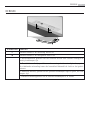
AEG DF7290-M Benutzerhandbuch
- Kategorie
- Dunstabzugshauben
- Typ
- Benutzerhandbuch
Dieses Handbuch eignet sich auch für

DF7190-M
DF7290-M
LIBRETTO ISTRUZIONI
USER MANUAL
BEDIENUNGSANLEITUNG
GEBRUIKSAANWIJZING
IT
EN
DE
NL
CAPPA
COOKER HOOD
DUNSTABZUGSHAUBE
AFZUIGKAP
3
12
21
30


PER RISULTATI PERFETTI
Grazie per aver scelto di acquistare questo prodotto AEG. Lo
abbiamo creato per fornirvi prestazioni impeccabili per molti
anni, grazie a tecnologie innovative che vi semplificheranno
la vita - funzioni che non troverete sui normali elettrodo-
mestici. Vi invitiamo di dedicare qualche minuto alla lettura
per sapere come trarre il massimo dal vostro elettrodomesti-
co.
ACCESSORI E PRODOTTI DI CONSUMO
All'interno del webshop AEG troverete tutto ciò che vi ser-
ve per fare in modo che i vostri elettrodomestici AEG siano
sempre perfettamente puliti e funzionanti. Non mancano
inoltre una vasta gamma di accessori studiati e realizzati
conformemente agli elevati standard qualitativi che vi aspet-
tate: pentole, scolaposate, portabottiglie e sacchi biancheria
delicati...
Visit the webshop at:
www.aeg-electrolux.com/shop

4
CONTENUTI
5
6
8
10
11
Consigli e suggerimenti
Caratteristiche
Installazione
Uso
Manutenzione
Contenuti

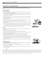
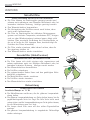
CONSIGLI E SUGGERIMENTI
5
CONSIGLI E SUGGERIMENTI
Questo libretto di istruzioni per l’uso è previsto per più versioni dell’ apparecchio. É
possibile che siano descritti singoli particolari della dotazione, che non riguardano il
Vostro apparecchio.
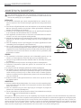
INSTALLAZIONE
• Ilproduttoredeclinaqualsiasiresponsabilitàperdannidovutiadinstallazionenoncorret-
ta o non conforme alle regole dell’arte.
• LadistanzaminimadisicurezzatrailPianodicotturaelaCappadeveesseredi650mm,
(alcuni modelli possono essere installati ad un’altezza inferiore, fare riferimento ai para-
grafi ingombro e installazione).
• Verificare chelatensionediretecorrispondaaquellariportatanellatarghetta posta
all’interno della Cappa.
• PerApparecchiinClasseIaaccertarsichel’impiantoelettricodomesticogarantiscaun
corretto scarico a terra.
• CollegarelaCappaall’uscitadell’ariaaspiratacontubazionedidiametropariosuperiore
a 120 mm. Il percorso della tubazione deve essere il più breve possibile.
• NoncollegarelaCappaacondottidiscaricodeifumiprodottidacombustione(caldaie,
caminetti, ecc.).
• NelcasoincuinellastanzavenganoutilizzatisialaCappacheapparecchinonazionati
da energia elettrica (ad esempio apparecchi utilizzatori di gas), si deve provvedere ad una
aerazione sufficiente dell’ambiente. Se la cucina ne fosse sprovvista, praticare un’apertura
che comunichi con l’esterno, per garantire il richiamo d’aria pulita.
USO
• LaCappaèstataprogettataesclusivamenteperusodomestico,perabbatteregliodori
della cucina.
• NonfaremaiusoimpropriodellaCappa.
• NonlasciarefiammelibereaforteintensitàsottolaCappainfunzione.
• Regolaresemprelefiammeinmododaevitareunaevidentefuoriuscitalateraledelle
stesse rispetto al fondo delle pentole.
• Controllarelefriggitricidurantel’uso:l’oliosurriscaldatopotrebbeinfiammarsi.
• Nonprepararealimentiflambèsottolacappadacucina;pericolod’incendio.
• Questoapparecchionondeveessereutilizzatodapersone(bambiniinclusi)conridotte
capacitàpsichiche,sensorialiomentali,oppuredapersonesenzaesperienzaeconoscen-
za, a meno che non siano controllati o istruiti all’uso dell’apparecchio da persone respon-
sabili della loro sicurezza.
• Ibambinidevonoesseresupervisionatiperassicurarsichenongiochinoconl’apparec-
chio.
MANUTENZIONE
• Primadiprocedereaqualsiasioperazionedimanutenzione,disinserirelaCappatogliendo
la spina elettrica o spegnendo l’interruttore generale.
• EffettuareunascrupolosaetempestivamanutenzionedeiFiltrisecondogliintervallicon-
sigliati (Rischio di incendio).
• PerlapuliziadellesuperficidellaCappaèsufficienteutilizzareunpannoumidoedeter-
sivo liquido neutro.
Il simbolo sul prodotto o sulla confezione indica che il prodotto non deve essere considerato come un normale rifiuto domestico, ma
deve essere portato nel punto di raccolta appropriato per il riciclaggio di apparecchiature elettriche ed elettroniche. Provvedendo a smaltire
questo prodotto in modo appropriato, si contribuisce a evitare potenziali conseguenze negative per l’ambiente e per la salute, che potreb-
bero derivare da uno smaltimento inadeguato del prodotto. Per informazioni più dettagliate sul riciclaggio di questo prodotto, contattare
l’ufficio comunale, il servizio locale di smaltimento rifiuti o il negozio in cui è stato acquistato il prodotto.

CARATTERISTICHE
6
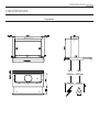
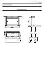
CARATTERISTICHE
Ingombro

CARATTERISTICHE
7
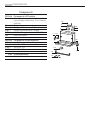
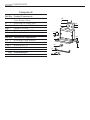
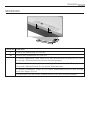
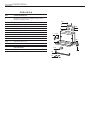
Componenti
Rif. Q.tà Componenti di Prodotto
1 1 Corpo Cappa completo di: Comandi,
Luce, Gruppo Ventilatore, Filtri, Camino
Inferiore
8 1 Griglia direzionata uscita aria
9 1 Flangia di Riduzione ø 150 mm
10a 1 Flangia di Riduzione ø 120 mm
10b 1 Anello di Maggiorazione ø 120-125 mm
20 Profilo chiusura
Rif. Q.tà Componenti di Installazione
7.1 2 Staffe Fissaggio Corpo Cappa
12a 8 Viti 3,5 x 16
12e 2 Viti 2,9 x 12,7
12f 5 Viti 2,9 x 9,5
Q.tà Documentazione
1 Libretto Istruzioni
12e
8
9
1
12a
20
12f
10a
10b
12a
7.1
12a
7.1

INSTALLAZIONE
8
INSTALLAZIONE
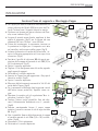
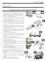
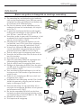
Foratura Piano di supporto e Montaggio Cappa
•LaCappapuòessereinstallatadirettamentesul
piano inferiore dei Pensili (650 mm min. dal Pia-
no di Cottura) con i Supporti laterali a scatto.
•PraticareunincassosulpianoinferioredelPen-
sile, come indicato (fig.1).
•Incasodipensilesenzafondo,applicareledue
staffe di supporto (fig.2) per la cappa ad una
distanza B di min. 30 mm - max. 60 mm.
•Primadelmontaggio,ènecessariorimuove-re
le protezioni in legno per il trasporto avvi-tate
sul carrello e sulla scocca della cappa. (fig.3)
•Inbasealdiametrodiuscitadell’ariascelto,in-
serire la flangia appropriata nel foro supe-riore
di scarico. (fig.4)
•Avvitareilprofilodichiusura20 alla parte po-
steriore della cappa utilizzando le viti 12f (2,9 x
9,5) in dotazione. (fig.5)
•Aprireilcarrelloaspirante.
•TogliereiFiltriAntigrassounoallavolta,agendo
sugli appositi agganci.
•Richiudereilcarrelloaspirante.
•InserirelaCappafinoadagganciareiSup-porti
laterali a scatto. (fig.6)
•Aprireilcarrelloaspirante.
•BloccaredefinitivamenteserrandoleVitiVfdal
sotto della Cappa. (fig.6)
•Seènecessarioeffettuaredegliaggiusta-menti
dell’intero corpo portafiltri, operare come se-
gue:
•AllentarelequattrovitidiregolazioneVr e ri-
chiudere il carrello. (fig.7)
•Traslarel’interocorpo portafiltrifino ad otte-
nere l’allineamento desiderato con il pensile.
(fig.8)
•Sempre mantenendo fermo il corpo cappa
estrarre il carrello e serrare le viti di rego-lazione
Vr. (fig.7)
•Oraèpossibilefissaredefinitivamentelacappa
al pensile usando le viti 12a (3,5 x 16) in dota-
zione. (fig.9)
•RimontareiFiltriantigrasso.
•Richiudereilcarrelloaspirante.
1
3
DE
1
10
MONTAGE
Bohren der Trägerplatte und Montage der Dunstabzugshaube
• Die Haube kann direkt an der Unterseite der
Hängeschränke (mindestens 650 mm von der
Kochmulde entfernt) mit seitlichen Schnapphal-
terungen fixiert werden.
• An der Unterseite des Hängeschranks, wie in
der Abbildung gezeigt, eine Öffnung anbringen.
(Abb.1)
• Sofern ein Schrank ohne Unterboden benutzt
werden soll, sind die verzinkten Haltewinkel mit
einem Abstand B von 30 bis 60 mm anzubrin-
gen. (Abb.2)
• Vor dem Einbau müssen die als Transportsiche-
rung auf dem Schirm geschraubten Holzleisten
abgenommen werden. (Abb.3)
• Je nach Durchmesser des gewählten Luftaus-
tritts den passenden Flansch in die obere Ab-
luftöffnung einsetzen. (Abb.4)
• Das Abschlussprofil 20 an der Rückseite der
Haube mit den beiliegenden Schrauben 12f
(2,9x9,5) fixieren. (Abb.5)
• Den herausziehbaren Wrasenleitschirm öffnen.
• Die Fettfilter nacheinander entnehmen, indem
die entsprechenden Haltevorrichtungen gelöst
werden.
• Den herausziehbaren Wrasenleitschirm wieder
schließen.
• Die Haube einschieben, bis die seitlichen Halte-
rungen einschnappen. (Abb.6)
• Den herausziehbaren Wrasenleitschirm öffnen.
• Die Haube von unten her mit den Schrauben Vf
fixieren. (Abb.6)
• Falls erforderlichk, das unter Teil wie nachste-
hend beschrieben ausrichten:
• Die vier Einstellschrauben Vr lockern und
den Wrasenleitschirm wieder schließen.
(Abb.7)
• Den gesamten unteren Korpus verschieben,
bis er auf den Oberschrank ausgerichtet ist.
(Abb.8)
• Den Haubenkörper festhalten, den Wrasen-
leitschirms öffnen und die Einstellschrauben
festziehen. (Abb.7)
• Nun kann die Haube am Oberschrank mit den
vier beiliegenden Schrauben 12a (3,5 x 16)
fixiert werden. (Abb.9)
• Die Fettfilter wieder montieren.
• Den herausziehbaren Wrasenleitschirm wieder schließen
1
2
3
4
6
Vr
7
8
9
5
5
6
9
10a
10a
10b
2
4
7
12a
8
9
B

INSTALLAZIONE
9
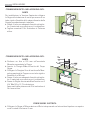
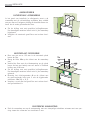
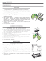
CONNESSIONIUSCITA ARIA VERSIONE ASPI-
RANTE
Per installazione in Versione Aspirante collegare
la Cappa alla tubazione di uscita per mezzo di un
tubo rigido o flessibile dello stesso diametro della
flangia precedentemente installata
•Fissareiltuboconadeguatefascettestringitu-
bo. Il materiale occorrente non è in dotazione.
•Togliereeventuali Filtri Antiodore alCarbone
attivo.
CONNESSIONIUSCITA ARIA VERSIONE ASPI-
RANTE
•Praticare un foro ø 125 mm sull’eventuale
Mensola soprastante la Cappa.
•Inserire la Flangia 10a sull’uscita del Corpo
Cappa.
•CollegarelaFlangiaalforodiuscitasullaMen-
sola soprastante la Cappa con un tubo rigido o
flessibile di ø120 mm.
•Fissareiltuboconadeguatefascettestringitu-
bo. Il materiale occorrente non è in dotazione.
•FissarelaGrigliadirezionata8 sull’uscita con 2
Viti 12e (2,9 x 12,7) in dotazione.
Assicurarsi della presenza dei Filtri antiodore al
Car-bone attivo.
12e
8
CONNESSIONE ELETTRICA
•CollegarelaCappaall’AlimentazionediReteinterponendounInterruttorebipolareconapertu-
ra dei contatti di almeno 3 mm.

USO
10
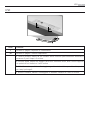
USO
Tasto Funzione
L Accende e spegne l’impianto di illuminazione.
M Accende e spegne il motore Aspirazione..
1. Velocità minima, adatta ad un ricambio d’aria continuo particolarmente silenzioso,in
presenza di pochi vapori di cottura.
2.Velocitàmedia,adattaallamaggiorpartedellecondizionid’uso,datol’ottimorapporto
tra portata d’aria trattata e livello sonoro.
3. Velocità massima, adatta a fronteggiare grandi emissioni di vapore di cottura,anche
per tempi prolungati..
i.Velocità intensiva, adatta a fronteggiarele massime emissioni di fumi di cottura.
L
M

MANUTENZIONE
11
MANUTENZIONE
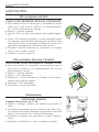
Filtri antigrassi metallici
PULIZIA FILTRI ANTIGRASSO METALLICI AUTOPORTANTI
•Sonolavabiliancheinlavastoviglie,enecessitanodiessere
lavati ogni 2 mesi circa di utilizzo o più frequentemente,
per un uso particolarmente intenso.
•Estrarreilcarrelloaspirante.
•TogliereiFiltriunoallavolta,agendosugliappositiaggan-
ci.
•LavareiFiltrievitandodipiegarli,elasciarliasciugareprima
di rimontarli. (Un’eventuale cambiamento del colore della
superficie del filtro, che potrebbe verificarsi nel tempo, non
pregiudica assolutamente l’efficienza dello stesso.)
•Rimontarli facendo attenzione a mantenere la maniglia
verso la parte visibile esterna.
•Chiudereilcarrelloaspirante.
Filtro antiodore (Versione Filtrante)
SOSTITUZIONE FILTRO ANTIODORE AL CARBONE ATTIVO
•Non sono lavabili né rigenerabili, vanno sostituiti ogni 4
mesi circa di utilizzo o più frequentemente, per un uso
particolarmente intenso.
•Estrarreilcarrelloaspirante.
•TogliereiFiltriAntigrasso
•Rimuovere il Filtro antiodore al Carbone attivo saturo,
agendo sugli appositi agganci.
•RimontareiFiltriantigrasso.
•Richiudereilcarrelloaspirante.
Illuminazione
SOSTITUZIONE LAMPADE
Lampada fluorescente da 11 W.
•Togliere i terminali metallici che fissano la plafoniera in
vetro.
•Farscorrerelaplafonierainvetroversounlato,finoalibe-
rarel’estremitàopposta.Abbassareleggermentel’estremità
libera e farlo scorrere fino a liberarlo totalmente.
•Sostituire la lampada con una nuova di uguali caratteri-
stiche.
•Rimontarelaplafonierainvetroin sequenza inversa.

FOR PERFECT RESULTS
Thank you for choosing this AEG product. We have created
it to give you impeccable performance for many years, with
innovative technologies that help make life simpler – featu-
res you might not find on ordinary appliances. Please spend
a few minutes reading to get the very best from it.
ACCESSORIES AND CONSUMABLES
In the AEG webshop, you’ll find everything you need to keep
all your AEG appliances looking spotless and working per-
fectly. Along with a wide range of accessories designed and
built to the high quality standards you would expect, from
specialist cookware to cutlery baskets, from bottle holders to
delicate laundry bags…
Visit the webshop at:
www.aeg-electrolux.com/shop

13
CONTENTS
14
15
17
19
20
Recommendations And Suggestions
Characteristics
Installation
Use
Maintenance
Contents

RECOMMENDATIONS AND SUGGESTIONS
14
RECOMMENDATIONS AND SUGGESTIONS
The Instructions for Use apply to several versions of this appliance. Accordingly, you
may find descriptions of individual features that do not apply to your specific appli-
ance.
INSTALLATION
• Themanufacturerwillnotbeheldliableforanydamagesresultingfromincorrector
improper installation.
• Theminimumsafetydistancebetweenthecookertopandtheextractorhoodis650mm
(some models can be installed at a lower height, please refer to the paragraphs on work-
ing dimensions and installation).
• Checkthatthemainsvoltagecorrespondstothatindicatedontheratingplatefixedto
the inside of the hood.
• ForClassIappliances,checkthatthedomesticpowersupplyguaranteesadequateearth-
ing.
Connect the extractor to the exhaust flue through a pipe of minimum diameter 120 mm.
The route of the flue must be as short as possible.
• Donotconnecttheextractorhoodtoexhaustductscarryingcombustionfumes(boilers,
fireplaces, etc.).
• Iftheextractorisusedinconjunctionwithnon-electricalappliances(e.g.gasburning
appliances), a sufficient degree of aeration must be guaranteed in the room in order to
prevent the backflow of exhaust gas. The kitchen must have an opening communicating
directly with the open air in order to guarantee the entry of clean air.
USE
• Theextractorhoodhasbeendesignedexclusivelyfordomesticusetoeliminatekitchen
smells.
• Neverusethehoodforpurposesotherthanforwhichithasbendesigned.
• Neverleavehighnakedflamesunderthehoodwhenitisinoperation.
• Adjusttheflameintensitytodirectitontothebottomofthepanonly,makingsurethat
it does not engulf the sides.
• Deepfatfryersmustbecontinuouslymonitoredduringuse:overheatedoilcanburstinto
flames.
• Donotflambèundertherangehood;riskoffire
• Thisapplianceisnotintendedforusebypersons(includingchildren)withreducedphysi-
cal, sensory or mental capabilities, or lack of experience and knowledge, unless they have
been given supervision or instruction concerning use of the appliance by a person re-
sponsible for their safety.
• Childrenshouldbesupervisedtoensurethattheydonotplaywiththeappliance.
MAINTENANCE
• Switchofforunplugtheappliancefromthemainssupplybeforecarryingoutanymain-
tenance work.
• Cleanand/orreplacetheFiltersafterthespecifiedtimeperiod(Firehazard)
• Cleanthehoodusingadampclothandaneutralliquiddetergent.
The symbol on the product or on its packaging indicates that this product may not be treated as household waste. Instead it shall be
handed over to the applicable collection point for the recycling of electrical and electronic equipment. By ensuring this product is disposed
of correctly, you will help prevent potential negative consequences for the environment and human health, which could otherwise be
caused by inappropriate waste handling of this product. For more detailed information about recycling of this product, please contact your
local city office, your household waste disposal service or the shop where you purchased the product.

CHARACTERISTICS
15
CHARACTERISTICS
Dimensions

CHARACTERISTICS
16
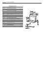
Components
Ref. Q.ty Product Components
1 1 Hood Body, complete with: Controls,
Light, Blower, Filters
8 1 Directional Air Outlet grille
9 1 Reducer Flange ø 150 mm
10a 1 Flange ø 120 mm
10b 1 Adapting ring ø 120-125 mm
20 Closing element
Ref. Q.ty Installation Components
7.1 2 Hood Body Fixing Brackets
12a 8 Screws 3,5 x 16
12e 2 Screws 2,9 x 12,7
12f 5 Screws 2,9 x 9,5
Q.ty Documentation
1 Instruction Manual
12e
8
9
1
12a
20
12f
10a
10b
12a
7.1
12a
7.1

INSTALLATION
17
INSTALLATION
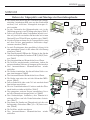
Drilling the Support surface and Fitting the Hood
•TheHoodcanbefitteddirectlyonthelowersur-
face of the Wall Units (650 mm min. above the
Cooker Top) using the snap-on Side Supports.
•Make an opening on the lower surface of the
Wall Unit, as indicated. (fig.1)
•If the cabinet is without bottom, fix the two
brackets at a distance B of minimum 30mm and
maximum 60mm. (fig.2)
•Beforecarryingouttheinstallation,thewooden
transportation protections screwed on the vi-
sor and on the canopy body must be removed.
(fig.3)
•Choosethecorrectflangemeasurebasingonthe
air outlet diameter and insert it to the upper air
outlet opening. (fig.4)
•Screwtheclosingprofile20 onto the rear part
of the hood, using the screws 12f (2.9 x 9.5) pro-
vided. (fig.5)
•Opentheslidingsuctionpanel.
•Removethemetalgreasefiltersonebyoneafter
having disconnected the relative fas-tening ele-
ments.
•Closetheslidingsuctionpanelagain.
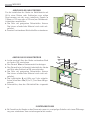
•InserttheHooduntilthesnap-onsidesup-ports
click into place. (fig.6)
•Opentheslidingsuctionpanel.
•LockinpositionbytighteningthescrewsVffrom
underneath the Hood. (fig.6)
•Ifnecessary,adjustthewhole filter holder unit
and proceed as follows:
•LoosenthefouradjustmentscrewsVrandclose
the sliding panel again. (fig.7)
•Movetheentirefilterholderunituntilitisprop-
erly aligned with the wall unit. (fig.8)
•Keepingthehoodcanopystill,removetheslid-
ingpanelandlocktheadjustmentscrewsagain.
(fig.7)
•Thehoodcannowbefastenedtothewallunit
using the four screws 12a (3.5 x 16) provided.
(fig.9)
•Replacethemetalgreasefilters.
•Closetheslidingsuctionpanelagain.
3
DE
1
10
MONTAGE
Bohren der Trägerplatte und Montage der Dunstabzugshaube
• Die Haube kann direkt an der Unterseite der
Hängeschränke (mindestens 650 mm von der
Kochmulde entfernt) mit seitlichen Schnapphal-
terungen fixiert werden.
• An der Unterseite des Hängeschranks, wie in
der Abbildung gezeigt, eine Öffnung anbringen.
(Abb.1)
• Sofern ein Schrank ohne Unterboden benutzt
werden soll, sind die verzinkten Haltewinkel mit
einem Abstand B von 30 bis 60 mm anzubrin-
gen. (Abb.2)
• Vor dem Einbau müssen die als Transportsiche-
rung auf dem Schirm geschraubten Holzleisten
abgenommen werden. (Abb.3)
• Je nach Durchmesser des gewählten Luftaus-
tritts den passenden Flansch in die obere Ab-
luftöffnung einsetzen. (Abb.4)
• Das Abschlussprofil 20 an der Rückseite der
Haube mit den beiliegenden Schrauben 12f
(2,9x9,5) fixieren. (Abb.5)
• Den herausziehbaren Wrasenleitschirm öffnen.
• Die Fettfilter nacheinander entnehmen, indem
die entsprechenden Haltevorrichtungen gelöst
werden.
• Den herausziehbaren Wrasenleitschirm wieder
schließen.
• Die Haube einschieben, bis die seitlichen Halte-
rungen einschnappen. (Abb.6)
• Den herausziehbaren Wrasenleitschirm öffnen.
• Die Haube von unten her mit den Schrauben Vf
fixieren. (Abb.6)
• Falls erforderlichk, das unter Teil wie nachste-
hend beschrieben ausrichten:
• Die vier Einstellschrauben Vr lockern und
den Wrasenleitschirm wieder schließen.
(Abb.7)
• Den gesamten unteren Korpus verschieben,
bis er auf den Oberschrank ausgerichtet ist.
(Abb.8)
• Den Haubenkörper festhalten, den Wrasen-
leitschirms öffnen und die Einstellschrauben
festziehen. (Abb.7)
• Nun kann die Haube am Oberschrank mit den
vier beiliegenden Schrauben 12a (3,5 x 16)
fixiert werden. (Abb.9)
• Die Fettfilter wieder montieren.
• Den herausziehbaren Wrasenleitschirm wieder schließen
1
2
3
4
6
Vr
7
8
9
5
5
6
9
10a
10a
10b
2
4
7
12a
8
9
B

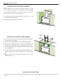
INSTALLATION
18
12e
8
CONNECTION IN DUCTING VERSION
When installing the hood in ducting version, a rigid
or a flexible pipe with the diameter corresponding
to the flange diameter is used in order to connect
the hood to the air outlet piping.
•Fix the pipewithan adequate quantityof pipe
clamps (not supplied).
•Removepossiblecharcoalfilters.
CONNECTION IN RECYCLING VERSION
•Cutaholeø125mminanyshelfthatmaybeposi-
tioned over the hood.
•Inserttheflange10a on the hood body outlet.
•Connecttheflangetotheoutletontheshelfover
the hood using a flexible or rigid pipe ø120 mm.
•Fixthepipeinpositionusingsufficientpipeclamps
(not supplied).
•Fixthedirectionalgrille8 on the recirculation air
outlet using the 2 screws 12e (2,9 x 12,7) provid-
ed.
•Ensure that the activated charcoal filters have
been inserted.
ELECTRICAL CONNECTION
•Connectthehoodtothemainsthroughatwo-poleswitchhavingacontactgapofatleast3
mm.

USE
19
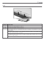
USE
SWITCH FUNCTIONS
L Switches the lighting system on and off
M Switches the extractor motor on and off
1. Low speed, used for a continuous and silent air change in the presence of light co-
oking vapour..
2. Medium speed, suitable for most operating conditions, thanks to an optimum relation
between hood performance and noise.
3. Maximum speed, suitable when the highest cooking vapour emission has to be elimi-
nated for longer periods.
i. Intensive speed, suitable for the strongest cooking vapours and odours.
L
M

MAINTENANCE
20
MAINTENANCE
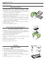
Metal grease filters
CLEANING METAL SELF- SUPPORTING GREASE FILTERS
•The filters must be cleaned every 2 months, or more
frequently in case of particularly heavy use of the hood.
Filters can be washed in a dishwasher.
•Pullouttheslidingsuctionpanel.
•Removethefiltersonebyone,afterhavingdisconnected
the relative fastening elements.
•Washthe filters,takingcarenot tobendthem. Letthem
get dry before refitting them. (The colour of the filter
surface may change throughout the time but this has no
influence to the filter efficiency).
•When refitting the filters, make sure that the handle is
visible on the outside.
•Closetheslidingsuctionpanel.
Charcoal Filter (Recycling Version)
REPLACING CHARCOAL FILTERS
•Thesefiltersarenotwashableandcannotberegenerated,
and must be replaced approximately every four months or
more frequently by particularly heavy use.
•Pullouttheslidingsuctionpanel.
•Removethegreasefilters.
•Removethesaturatedcarbonfilterbyreleasingthefixing
hooks
•Fitthenewfilterbyhookingitintoitsseating.
•Replacethegreasefilters.
•Closetheslidingsuctionpanel.
Lighting
LIGHT REPLACEMENT
11 W fluorescent light
• Remove the metal terminals fixing the glass.
• Slide the glass cover out of one of the fastening clips.
Lower the unfastened part of the glass cover slightly, so
that the cover can be completely removed.
• Replace the light with a new one of the same type and
rating.
• Replace the glass cover in reverseorder.
Seite wird geladen ...
Seite wird geladen ...
Seite wird geladen ...
Seite wird geladen ...
Seite wird geladen ...
Seite wird geladen ...
Seite wird geladen ...
Seite wird geladen ...
Seite wird geladen ...
Seite wird geladen ...
Seite wird geladen ...
Seite wird geladen ...
Seite wird geladen ...
Seite wird geladen ...
Seite wird geladen ...
Seite wird geladen ...
Seite wird geladen ...
Seite wird geladen ...
Seite wird geladen ...
Seite wird geladen ...
-
 1
1
-
 2
2
-
 3
3
-
 4
4
-
 5
5
-
 6
6
-
 7
7
-
 8
8
-
 9
9
-
 10
10
-
 11
11
-
 12
12
-
 13
13
-
 14
14
-
 15
15
-
 16
16
-
 17
17
-
 18
18
-
 19
19
-
 20
20
-
 21
21
-
 22
22
-
 23
23
-
 24
24
-
 25
25
-
 26
26
-
 27
27
-
 28
28
-
 29
29
-
 30
30
-
 31
31
-
 32
32
-
 33
33
-
 34
34
-
 35
35
-
 36
36
-
 37
37
-
 38
38
-
 39
39
-
 40
40


AEG DF7290-M Benutzerhandbuch
- Kategorie
- Dunstabzugshauben
- Typ
- Benutzerhandbuch
- Dieses Handbuch eignet sich auch für
in anderen Sprachen
- English: AEG DF7290-M User manual
- italiano: AEG DF7290-M Manuale utente
- Nederlands: AEG DF7290-M Handleiding
Andere Dokumente
-
Aeg-Electrolux 7509D-M/A Benutzerhandbuch
-
-
Aeg-Electrolux EFP6519 Benutzerhandbuch
-
-
Progress PDP9030E Benutzerhandbuch
-
 Franke Consumer Products FTC 622 Benutzerhandbuch
-
ROBLIN PEGASE Bedienungsanleitung
-
Electrolux EFP60241X Benutzerhandbuch
-
Juno JDA 5271 X (German) Bedienungsanleitung
-
Bauknecht DNG 5355 IX-1 Installationsanleitung
