
No.
8400, 8401, 8402
Bedienungsanleitung / Operating instructions / Notice d'utilisation
Mikroprozessor - Fahrtregler Rookie 20,25,35 WP
P
reisgünstige Regler für Auto- und Schiffsmodelle mit 540er Standard- und Tuning-Motoren
von 35 A = ab 12 turns, 25 A = ab 15 turns, 20 A = ab 16 turns, z. B. Power 600/19 und
6
00/24 oder EF 76.
Mit Acryl-Lack-Versiegelung zum Schutz vor Spritzwasserschäden.
Eigenschaften
Elektronischer Fahrtregler mit Vorwärts - Neutral - Brems/Rückwärts - Funktion. Vollwertige
Rückwärtsstufe für Elektro-RC-Cars, Trucks und Schiffsmodelle. Mikroprozessorgesteuert,
mit hoher Motortaktfrequenz für Standard- und Tuning-Motoren. Getriebeschonend durch
s
pezielle Anordnung von dynamischer Bremse und Rückwärtsstufe.
- Hochwertige, flexible Silikon-Anschlußkabel
-
Verschleißfreie Endstufe ohne Relais
Besonderheiten
FET
- Power-MOS-Feldeffekttransistoren
BEC - Empfängerstromversorgung
hec - Hohe Taktfrequenz zur feinfühligen, proportionalen Steuerung und Magnet
schonung
POR
- Anlaufschutz, verhindert ungewolltes Anlaufen des Motors
TP - Übertemperaturschutz
PCO - Unterspannungsabschaltung
RXF - Rx-Filter, schaltet den Regler bei fehlendem oder ungültigem Sendersignal aus
EPS - Einfachste Programmierung
WP - Spritzwasserschutz durch Lackversiegelung
TASTER - Eingabetaste zur Programmierung
LED - LED Anzeige von Betriebs- und Programmierfunktion
Technische Daten
Funktion: Vorwärts, Neutral, dynamische Bremse, Rückwärts
Betriebsspannung: 5 - 10 NC NiMH oder 6 V und 12 V Bleiakku
Motorstrom: 20 A / 25 A / 35 A
BEC: 5 V, max 2 - 3 Servos
Abmessungen: 37 x 45 x 25 mm
Gewicht: 60 g
Stecksystem: 1,5 mm
2
/ No. 8402 2,5mm
2
JST / TAM
Erläuterungen zu den technischen Daten
Unter dem Motorstrom ist der mittlere Dauerstrom bei "Vollgas vorwärts" zu verstehen, der
für die Dauer einer Akkuentladung (1700 mAh) fließen kann. Die Ströme sind abhängig vom
Modell und vom individuellen Fahrstil. Kurzzeitige, höhere Spitzenströme sind problemlos
möglich.
Mit dem BEC System dürfen bei 8 - 10 NC- Zellen max. 2 Servos und bei 5 - 7 NC-Zellen
max. 3 Servos betrieben werden.
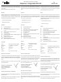
Bei Verwendung eines separaten Empfängerakkus
die rote Leitung am Empfängeranschluß
des Reglers aus dem Steckergehäuse "S"
ziehen und isolieren.
Funktionsweise der dynamischen Bremse und der Rückwärtsstufe
Nach V
erlassen des V
orwärtsfahrber
eiches wir
d der Rückwärtsfahrber
eich kurzzeitig als pro-
portionale Br
emse benutzt.
Anschließend dient dieser Ber
eich zum stufenlosen Rückwärtsfahr
en. Der Über
gang von
"Br
emse" nach "Rückwärts" erfolgt nicht abrupt sonder
n schonend.
"S"
V
ariateurs bon marché pour modèles d’autos et de bateaux équipés de moteurs de la série
540, standard et compétition, avec 35 A = à partir de 12 spires, 25 A = à partir de 15 spires,
2
0 A = à partir de 16 spires, par ex. Power 600/19 et 600/24 ou EF76. Avec scellement par
panneau en plastique transparent contre les projections d’eau .
Propriétés
Très petit variateur électronique léger et bon marché avec marche arrière à puissance inté-
grale pour les autos, les camions et les bateaux électriques. Pilotés par microprocesseur
avec haute fréquence d’impulsion pour la protection du moteur standard et des moteurs de
c
ompétition. Traitement sans usure des engrenages par une disposition spéciale du frein
dynamique et de l’étage marche arrière.
- cordon hautement flexible avec gaine silicone
- étage final sans usure sans relais
Spécificités
FET - transistors de puissance MOS à effet de champ
BEC - alimentation du récepteur
hec - haute fréquence d’impulsion du moteur pour en épargner l’aimant
POR
- protection contre les démarrages intempestifs du moteur
TP - protection contre les températures excessives intégrée
PCO - protection contre la sous-tension
RXF - filtre Rx - coupe le variateur en l’absence de signaux valables en provenance de
l’émetteur
EPS - programmation simple
WP - électronique protégée contre les projections d’eau par scellement par panneau
en plastique transparent
TASTER - une seule touche de programmation
LED - affichage à LED pour les fonctions de service et de programmation
Caractéristiques techniques
fonctions: marche avant, neutre, frein dynamique, marche arrière
tension de service: 5-7 éléments Cd-Ni NiMH (ou accu au PB 6 / 12 volts)
courant de charge : 20 A / 25 A /35 A
BEC: 5 V, max. 2 à 3 servos
encombrement: approx. 37 x 45 x 25 mm
poids:
60 g
système de connexion : 1,5 mm
2
/ réf. 8402 2,5mm
2
JST / TAM
Explication des caractéristiques techniques
Par courant moteur on entend le courant longue durée moyen à „plein gaz marche avant“
qui est susceptible d’être fourni sur la durée d’une charge d’accu (1700 mAh). Les courants
dépendent du modèle et du style individuel de pilotage. Brièvement des pointes de courant
plus importantes sont possibles sans problème.
Avec le système BEC il est possible d’exploiter un maximum de 2 servos avec 8 à 10 élé-
ments Cd-Ni et un maximum de 3 servos avec 5 à 7 éléments Cd-Ni.
Si vous utilisez un accu autonome pour le récepteur,
retirer le brin rouge au niveau du raccord du variateur
au récepteur au niveau du boîtier
de connexion „S“ et l’isoler.
Mode de fonctionnement du frein dynamique et de la marche arrière
Après avoir quitté le secteur de la mar
che avant, le secteur de la mar
che arrièr
e est exploité
brièvement comme un fr
ein pr
oportionnel.
Ensuite, ce secteur fait of
fice de mar
che arrièr
e en continu. Le passage de „fr
ein“ à „mar
che
arrièr
e“ n’intervient pas de manièr
e abrupte mais de manièr
e souple.
"S"
Low-cost speed controllers for model cars and boats fitted with 540-size standard and “tun-
ing” electric motors with 35 A = from 12 turns, 25 A = from 15 turns, 20 A = from 16 turns,
e.g. Power 600/19 and 600/24 or EF 76. Sealed with acrylic lacquer to guard against spray
damage.
C
haracteristics
E
lectronic speed controller with forwards - neutral - reverse functions. Full reverse stage for
electric model cars, trucks and boats. Micro-processor controlled, with high motor pulse fre-
q
uency for standard and “tuning” motors. Special arrangement of dynamic brake and
reverse stage protects the gearbox from damage.
- High-quality high-flex silicone power cables
- Relay-less output stage; no parts to wear
Special features
FET - Power MOS-FET field effect transistors
BEC - Integral receiver power supply
hec - high pulse frequency for fine proportional control and magnet protection
POR - Power-on protection, prevents motor starting up accidentally
TP - Excess temperature protection
PCO - Low voltage power-off
RXF - Rx filter, switches the controller off if the transmitter signal fails or is invalid
EPS - Ultra-simple programming
WP - Splashproof protective lacquer seal
BUTTON - Input push-button for programming
LED - LED indicator confirms operating and programming functions
Specification
Functions: Forwards, neutral, dynamic brake, reverse
Operating voltage: 5 - 10 NC NiMH or 6 V / 12 V lead/acid
Motor current: 20 A / 25 A / 35 A
BEC: 5 V, max. 2 - 3 servos
Dimensions: 37 x 45 x 25 mm
Weight: 60 g
Connector system:
1.5 mm
2
/
No. 8402 2.5mm
2
JST / T
AM
Specification - supplementary information
The motor curr
ent figur
e r
epr
esents the maximum permissible average continuous current
under “full thr
ottle forwar
ds” conditions for the duration of one full battery dischar
ge (1700
mAh cells). Currents vary from model to model and according to the operator’s driving style.
Higher peak currents present no problems provided that they are for brief periods.
If you ar
e using the BEC system with 8 - 10 NC cells the maximum number of servos is 2;
with 5 - 7 NC cells the maximum number is 3 servos.
If you wish to use a separate r
eceiver battery locate
the r
ed wir
e in the receiver lead attached
to the controller and withdraw it from
the plug housing “S”. Insulate the end carefully.
How the dynamic brake and reverse stages work
When the stick is initially moved back from the “forwards” range the reverse range operates
as a pr
oportional brake, but only for a brief period.
After this period this part of the stick travel operates as a proportional reverse mode. The
transition from “brake” to “reverse” mode takes place gently in order to avoid mechanical
damage.
"S"

No.
8400, 8401, 8402
Bedienungsanleitung / Operating instructions / Notice d'utilisation
Mikroprozessor - Fahrtregler Rookie 20, 25, 35 WP
Anschluß, erste Inbetriebnahme
- Sender einschalten.
-
Rx - Kabel des Reglers am entsprechenden Empfängerkanal
anschließen.
Bei Betrieb ohne BEC, rotes Kabel am Reglerstec-
k
er herausziehen und Empfängerakku anschließen.
- 5 - 10 NC-Zellen (Fahrakku) anschließen. Unbedingt auf richtige
P
olung achten.
- Das Blinken der LED in sehr kurzen Intervallen zeigt die Betriebs-
b
ereitschaft des Reglers an.
Steuerknüppel langsam hin- und her bewegen.
-
Am Fahrtregler wird der Vorwärtsbetrieb durch ein gleichmäßiges
Leuchten, der Rückwärtsbetrieb durch ein Blinken der LED an-
gezeigt. Befindet sich der Gasknüppel in Vorwärtstellung, muß
sich der Fahrtregler im Vorwärtsbetrieb befinden. Trifft dies nicht
zu, ist der Regler neu zu programmieren (siehe
„Programmierung").
- Der Motor muß im Vorwärtsbetrieb des Reglers "vorwärts" lau-
fen, ansonsten die Anschlüsse am Motor vertauschen.
Den
Motor nicht im Rückwärtsbetrieb vorwärts laufen lassen, dies
führt zu übermäßiger Belastung des Reglers.
Programmierung
Um in den Programmiermodus zu gelangen, muß die Fahrakkuspan-
nung kurz unterbrochen werden.
- Steuerknüppel nicht bewegen.
- Den Taster solange drücken, bis die LED gleichmäßig 1 mal blinkt.
- Den Knüppel in die Stellung „Vollgas vorwärts“ bringen und Taster
kurz betätigen. Die LED muß zweimal blinken.
- Den Knüppel in Neutralstellung bringen und Taster kurz betätigen.
Die LED muß dreimal blinken.
- Den Knüppel in die „Stellung „Vollgas rückwärts“ bringen. Taster
kurz betätigen.
- Der Regler ist betriebsbereit.
Ist keine Funktion gegeben und die LED blinkt wie beim ersten
Schritt, die Pr
ogrammierung (evtl. mit anderen Knüppelstellungen)
wiederholen.
Hinweis: Wird beim Programmieren die Neutralstellung mit einem
Doppelklick auf den Taster bestätigt, sind Rückwärts- und Brems-
funktion deaktiviert. Der Regler arbeitet nur im V
orwärtsbereich.
Der Regler ist nach Anschluß des Fahrakkus, länger anhaltenden
Funkstörungen, Unterspannungsabschaltung oder Temperaturab-
schaltung nicht mehr betriebsbereit.
Durch Wechsel der Gasknüppelpositionen (z. B. Vorwärts -
Rückwärts) wird dieser Zustand aufgehoben.
Sicherheitshinweise
- Technische Daten des Reglers beachten
- Akku nicht verpolen
- Kurzschlüsse der Kabel unbedingt vermeiden
- Antriebsmotor wirkungsvoll entstören
- Auf gute Luftzirkulation achten.
- Den Regler so einbauen bzw. verpacken, daß er nicht mit Fett
oder Öl in Berührung kommen kann.
r
obbe Modellsport GmbH & Co. KG
T
echnische Änderungen vorbehalten
Copyright r
obbe-Modellsport 2005
"S"
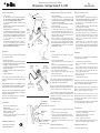
Motoranschluß
motor connection
Raccord moteur
Empfängeranschluß
R
eceiver connection
Raccord récepteur
Akkuanschluß
Battery connection
Raccord accu
LED
Fahrtregler
Motor con-
troller
Variateur
Motor
Motor
Moteur
Empfänger
Receiver
Récepteur
Fahrakku
Drive battery
Accu de propulsion
Akkuanschluß
rot = +, schwarz =-
Battery connection
red = +, black =-
Raccord accu
rouge = +, noir =-
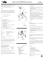
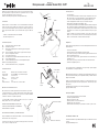
Motoranschluß
motor connection
Raccord moteur
Empfängeranschluß
Receiver connection
Raccord du récep-
teur
TASTER
Button
Touche
Neutralposition
Neutral
Neutr
e
Brems- / Rückwärtsbereich
Brake / reverse range
Zone de fr
einage / mar
che
arrière
V
orwärtsbereich
Forwards range
Zone de marche avant
Branchement, première mise en service
- mettre l’émetteur en marche
- raccorder le fil Rx à la voie correspondante du récepteur. Si le
système fonctionne sans BEC, retirer le brin rouge du con-
n
ecteur du variateur et raccorder l’accu du récepteur.
- raccorder l’accu de 5 à 10 éléments Cd-Ni (accu du moteur).
Attention à la polarité.
- le fait que la LED clignote avec de très courts intervalles indique
que le variateur est en ordre de marche
- déplacer lentement le manche de l’avant vers l’arrière
- sur le variateur, la marche avant est indiquée par le fait que la
LED est allumée en permanence alors que la LED clignote en
marche arrière. Lorsque le manche des gaz se trouve en marche
avant, il faut que le variateur se trouve également en marche
avant. Si ce n’est pas le cas, reprogrammer le variateur (cf.
„
Programmation“)
- lorsque le variateur se trouve en marche avant, le moteur doit
tourner en marche avant sinon, inverser les connexion du
moteur.
Ne pas laisser tourner l moteur en marche arrière alors
que le variateur est en marche avant, le variateur subit une
charge excessive.
Programmation
Pour accéder au mode programmation, il faut interrompre briève-
ment la tension de l’accu du moteur.
- ne pas déplacer le manche d’asservissement
- presser sur la touche jusqu’à ce que la LED clignote régulière-
ment 1 fois
- amener le manche des gaz en position „plein gaz avant“ et
presser brièvement sur la touche. La LED doit clignoter deux fois
- amener le manche au neutre et appuyer brièvement sur la
touche. La LED doit clignoter trois fois
- amener le manche en position „plein gaz arrière“. Appuyer
brièvement sur la touche
- le variateur est en ordre de marche.
En l’absence de fonction alors que la LED clignote comme pour la
première étape mentionnée, reprendre la programmation (si néces-
saire avec une autre programmation des manches).
À noter: lorsque la programmation du neutre est confirmée par un
double clic sur la touche, la marche arrière et le frein ne sont plus
efficaces. Le variateur ne travaille qu’en marche avant.
Après avoir raccor
dé l’accu du moteur, en présence de longs
dérangements de transmission et commutation de sous-tension ou
commutation du fait de température excessive, le variateur n’est
plus en ordre de marche.
Une modification de la position du manche des gaz (par ex. marche
avant - marche arrièr
e) permet de supprimer cet état.
Conseils de sécurité
-
tenir compte des caractéristiques techniques du variateur
-
ne pas inverser les polarités de l’accu
- éviter absolument de mettre les brins en court-circuit
- antiparasiter efficacement le moteur
-
veiller à ce que l’air cir
cule corr
ectement
-
installer ou emballer le variateur de telle manièr
e qu’il ne puisse
pas entrer en contact avec de la graisse ou de l’huile.
robbe Modellsport GmbH & Co. KG
Sous réserve de modification technique
Connecting the controller, using the system for the first time
- Switch on the transmitter.
-
Connect the Rx cable attached to the controller to the appropri-
ate receiver channel.
If you are not using the BEC system pull
o
ut the red wire from the controller plug, insulate the end and
connect a separate receiver battery.
-
Connect the 5 - 10 cell NC pack (drive battery). It is essential to
maintain correct polarity.
-
Move the throttle stick slowly forward and back.
- The LED will glow steadily when in the “forwards” range. In
“
reverse” the LED will flash. When the throttle stick is in the “for-
wards” part of its arc the speed controller must be in the “for-
wards” range. If this is not the case the controller needs to be re-
programmed (see “Programming”).
- When the controller is in the “forwards” range the motor must
also run in the direction corresponding to the model’s forward
motion. If not, swap over the connections at the motor terminals.
Do not leave the system “the wrong way round”, i.e. the motor
running forwards when the controller is in reverse mode, as
this overloads the contr
oller.
Programming
- To enter programming mode the drive battery voltage must be
disconnected briefly.
- Leave the throttle stick untouched.
- Hold the push-button pressed in until the LED flashes once
evenly.
- Move the stick to the “full throttle forwards” position and press
the button briefly. The LED should now flash twice.
- Move the stick to the neutral position and press the push-button
again. The LED should now flash three times.
- Move the stick back to the “full throttle reverse” position and
press the push-button again.
- The speed controller is now completely set up and ready to work.
If the contr
oller does not appear to work and the LED flashes at the
first stage of pr
ogramming, repeat the programming procedure (you
may find that different stick positions work better).
Note: You can disable the reverse and brake functions by giving a
double-pr
ess on the push-button when programming the neutral po-
sition. The controller now works over the forwards range only.
The controller will not work under the following conditions: immedi-
ately after you connect the drive battery, after a prolonged period of
radio interference, and after the low-voltage circuit or the excess
temperature circuit have tripped.
You can re-activate the controller by altering the throttle stick posi-
tion (e.g. forwar
ds - reverse).
Safety notes
- It is important to stay within the parameters listed in the Specifi-
cation.
- Do not connect the battery with reverse polarity.
- Take care to avoid short-circuits between the various cables.
- Provide adequate interference suppression for the electric motor.
-
Pr
ovide good air cir
culation to the contr
oller
.
-
Install the unit in such a way that it cannot come into contact with
gr
ease or oil.
r
obbe Modellsport GmbH & Co. KG
W
e r
eserve the right to alter technical specifications
Seite wird geladen ...
Seite wird geladen ...
-
 1
1
-
 2
2
-
 3
3
-
 4
4


in anderen Sprachen
- English: ROBBE 8400 Operating instructions
- français: ROBBE 8400 Mode d'emploi
- español: ROBBE 8400 Instrucciones de operación
- italiano: ROBBE 8400 Istruzioni per l'uso
Verwandte Artikel
Andere Dokumente
-
MULTIPLEX Roxxy Bl Control 908 Bedienungsanleitung
-
-
-
-
-