
USER’S OPERATING MANUAL
RG6-E-230V
Bosch Automotive Service Solutions GmbH
Lürriper Str. 62, 41065 Mönchengladbach, Germany
email: info@atp-europe.de www.atp-europe.de

Advanced Test Products RG6-E
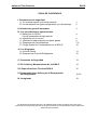
TABLE OF CONTENTS
I) Safety precautions
A) The safe way is the only way! 1
B) Refrigerant gas recovery & containment 2
II) Important general information 3
III) Operational procedures
A) Operating your RG6-E 4-6
Use of the Low Pressure (Vacuum) Switch 6
B) Set-up procedures 7-9
C) Purging the non-condensable gases 10
IV) Diagrams
A) Part list 11
B) Refrigerant flow diagram 12
V) Safety pressure switch 13
VI) Care and maintenance 14
VII) Technical data 15
VIII) Helpful hints 16-18
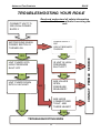
IX) Troubleshooting 19
Design specifications and material are subject to change without notice. REV$04'14A$
!
This manual may not be reproduced in any way, shape or form without express written consent of
Advanced Test Products.

THE SAFE WAY IS THE ONLY WAY!
NOTE! If you are not a qualified refrigerant service technician,
do not use this equipment
1. The technician should always wear goggles and gloves when working on
refrigeration systems.
2. Be sure that any room where you are working is thoroughly ventilated,
3. Always think before acting. Familiarity breeds carelessness and carelessness can
be harmful to your health or, worse, result in death.
4. Read the Material Safety Data Sheets (MSDS) on all compounds with which you
are likely to come in contact. Read MSDS on refrigerant and refrigerant oil. Obtain
MSDS sheets from your refrigerant supplier.
5. Never use oxygen when testing for leaks. Any oil in contact with oxygen under
pressure will form an explosive mixture.
6. Refrigerant systems are generally electrically driven and controlled. Be sure to
disconnect the unit from the power source before servicing it.
7. Always store refrigerant containers in a cool, dry place.
8. Always open service and cylinder valves slowly. This allows quick control of the flow
of gasses if there is any danger. Once it is determined that there is no danger, the
valves may be opened fully.
9. Do not mix refrigerant in a system, a tank or anywhere else. Each type of refrigerant
must have its own tank, filters, etc.
10. If moisture enters the refrigerant system, it is likely to cause considerable damage.
Keep everything connected with the refrigeration system thoroughly dry and clean.
11. To reduce the risk of fire, avoid the use of extension cords as they may overheat. If
you must use an extension cord it should be a minimum of 14 AWG and not longer
than 7,5m (25ft).
This equipment should be used in locations with mechanical ventilation providing at
least four air changes per hour, or the equipment should be located at least 45cm (18”)
above the floor. Do not use this equipment in the vicinity of spilled or open containers of
gasoline or any other flammable liquid.
1

Advanced Test Products RG6-E
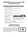
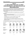
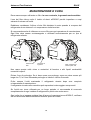
REFRIGERANT GAS
RECOVERY & CONTAINMENT
Safety comes first. Read all safety information for the safe handling of refrigerant
including the Material Safety Data Sheet provided by your refrigerant supplier. Never
operate unit in an explosive environment. Wear safety glasses and protective gloves.
Work area must be well ventilated. This unit should only be operated by a qualified
technician.
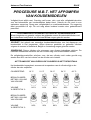
*** CAUTION: REFRIGERANT STORE CONTAINERS ***
Use only approved cylinders with a minimum of 41 bar (595PSI) working pressure that
serve the current regulations.
NOTE: Recovery cylinders are designed for different pressures. Do not exceed the
working pressure of each cylinder.
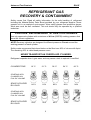
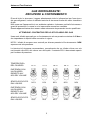
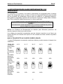
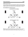
Safety codes recommend that closed tanks not be filled over 80% of volume with liquid.
The remaining 20% is called head pressure room.
NEVER TRANSPORT AN OVERFILLED CYLINDER.
Refrigerant expands when it gets warm and may cause a tank to explode if overfilled.
CYLINDER TEMP. 16 °C 21 °C 38 °C 54 °C 66 °C
STARTING WITH
CYLINDER 80%
FULL BY VOLUME
SPACE OCCUPIED
BY LIQUID
STARTING WITH
CYLINDER 90%
FULL BY VOLUME
SPACE OCCUPIED
BY LIQUID
80 % 81% 83% 90% 94%
90% 92% 96% 100%
2

Advanced Test Products RG6-E
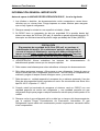
IMPORTANT
GENERAL INFORMATION
Before operating the RG6-E recovery unit, read the following:
1. Storage cylinders sometimes have valves that are not properly seated when
manufactured. Keeping caps on these valves will guard against refrigerant leakage.
2. Always operate the unit on a flat level surface.
3. Your RG6-E has one internal pressure shut off switch. If the pressure inside the
equipment should go above 38,5 bar (550 psi), the equipment will automatically
shut itself off. The switch will reset when the pressure drops below 28 Bar (400PSI).
CAUTION
The 38,5 bar (550 psi) switch does not prevent tank overfill. If your system shuts
off on high pressure and is connected to your tank, you may have overfilled your
tank and created a very dangerous situation! Take immediate measures to relieve
any high pressure and/or tank overfill.
4. WARNING! Never overfill storage tanks. Overfilling may cause tanks to explode.
5. A scale must be used to avoid overfilling the storage tank.
6. Tanks and filters should be designated for one refrigerant only. Before using a tank
previously used for another refrigerant, completely empty the tank, evacuate it,
purge the tank using dry nitrogen, and re-evacuate it.
7. Special care should be taken when recovering from a burned-out system. Use two
high acid capacity filters, in series. Alco® type EK-162-F or Sporlan® type C-162-F
are recommended.
8. When you have finished recovering from the system, flush your RG6-E with a small
amount of refrigerant oil and a small amount of clean refrigerant to purge off any
foreign substances left in the unit.
9. Always empty refrigerant from the unit into a storage tank; see Self Purge/Auto
Evacuate procedure. Liquid refrigerant left in the condenser may expand, causing
damage to components.
3

Advanced Test Products RG6-E
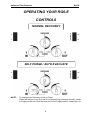
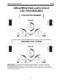
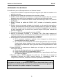
OPERATING YOUR RG6-E
CONTROLS
NOTE: To change from Recovery mode to Purge:
Close the Inlet port, turn the unit off (to prevent high pressure shutoff), switch
to Purge position and turn the Inlet port to the Purge position, restart the unit.
NORMAL RECOVERY
SELF PURGE / AUTO EVACUATE
4

Advanced Test Products RG6-E
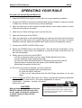
OPERATING YOUR RG6-E
Procedure for Normal System Recovery
1. Inspect the RG6-E thoroughly to insure that it is in good operating condition.
2. Connect the RG6-E to the service manifold and system as shown in figures on page
8. Make sure all hose connections are correct and tight.
3. Open the liquid port of the recovery cylinder (always open valves slowly to check
hoses and connections for leaks).
4. Make sure the Recover/Purge valve is set on Recover.
5. Open the Outlet port of the RG6-E.
6. Open the liquid port on the manifold gauge set; opening the liquid port will remove
the liquid from the system first, greatly reducing the recovery time (after the liquid
has been removed, open the manifold vapor port to finish evacuating the system).
7. Connect your RG6-E to a230V 50Hz outlet.
8. Switch the POWER switch to the ON position. This will start the compressor (it may
be necessary, under certain circumstances, to press this switch more than once to
start the compressor).
9. Slowly open the Inlet port on the RG6-E.
a) If the compressor starts to knock, slowly throttle back the Inlet valve
until the knocking stops (liquid hammering).
b) If the Inlet valve was throttled back, it should be fully opened once the
liquid has been removed from the system (the manifold vapor port
should also be opened at this time).
10. Run until your minimum required vacuum is achieved.
a) Close the manifold vapor and liquid ports.
b) Close the RG6-E Inlet port.
c) Shut unit off and proceed with the Self Purge procedure on the next
page.
11. Always purge the RG6-E after each use. Failure to purge the remaining refrigerant
from the RG6-E could result in the acidic degradation of internal
components, ultimately causing premature
failure of the unit.
CAUTION
When pumping liquid, do not allow the
RG6-E to operate with the Inlet valve
too far open, causing the compressor
to knock. Doing so may stall the
compressor.
5
* "$2'$3,(2-, 9 2*$4$*130% "$
-,,$"2 '-1$%0-+2'$(,*$21(#$-%2'$3,(22-
2'$*(/3(#.-02-%2'$1612$+!$(,&1$04("$#
-,,$"2 '-1$%0-+2'$-32*$21(#$-%2'$3,(2
2-2'$*(/3(#.-02-, 0$"-4$06"6*(,#$0
.$,2'$*(/3(#4 *4$-,2'$0$"-4$06"6*(,#$0
30,2'$0$"-4$0.30&$),-!2-
.$,2'$-32*$24 *4$-,2'$3,(2
-&&*$2'$.-5$015(2"'
3,2'$3,(23,2(*2'$#$1(0$#4 "33+(1
*-1$2'$(,*$2 ,#-32*$24 *4$1-,2'$3,(2
-&&*$2'$.-5$015(2"'
*-1$2'$.-021-,2'$0$"-4$06"6*(,#$0
Tech Tip
-0 % 12$00$"-4$06.0-"$#30$0$"-4$0%0-+!-2'
2'$*(/3(# ,#4 .-0.-021-%2'$1612$+!$(,&
1$04("$#!631(,& 2$$822(,&-0+ ,(%-*#& 3&$
set in the hose setup.
**-52'$12-0 &$"6*(,#$02-1(23,#(1230!$#%-0
'-3012- **-5 (02-0(1$2-2'$2-.
-,,$"2 + ,(%-*#& 3&$1$22-2'$"6*(,#$0
$ #2'$ +-3,2-%.0$1130$(,2'$"6*(,#$0 1
$2$0+(,$2'$ +!($,22$+.$0 230$(,2'$
$%$02- 0$%0(&$0 ,2.0$1130$2$+.$0 230$
"' 02 ,#8,#2'$ +!($,22$+.$0 230$$ #
"0 ")-.$,2'$4 .-0.-02
4 *4$'(1(1#-,$1*-5*62-" 31$ 1*(22*$
230!3*$,"$(,1(#$2'$"6*(,#$0 1.-11(!*$
2"'2'$.0$1130$-,2'$& 3&$#$"0$ 1$
-.0$4$,24$,2(,& ##7.1(2-2'$
.0$1130$1'-5,-,2'$"' 02'$,2'$& 3&$
**-52'$"6*(,#$02-1(2%-0+(,32$1 ,#2'$,
$.$ 22'$.0-"$11(%,$"$11 06

Advanced Test Products RG6-E
OPERATING YOUR RG6-E
Procedure for Purging Remaining Refrigerant From the RG6-E
1. Close the ports of the system being serviced that are connected to the Inlet
port of the RG6-E.
2. Close the Inlet port on the RG6-E.
3. Turn off RG6-E.
4. Turn the Recover/Purge valve to the purge position.
5. Turn the Inlet port to the purge position
6. Restart the RG6-E.
7. Run until desired vacuum is achieved.
8. Close the ports on the recovery tank and the RG6-E.
9. Turn the RG6-E off.
10. Return the Recover/Purge valve to the Recover position.
11. Disconnect and store all hoses.
12. Replace the in-line filter on your RG6-E after every time contaminant is
encountered.
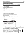
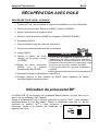
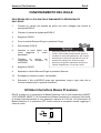
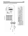
The use of the Low Pressure Switch
The RG6-E is equipped with a low pressure switch which
is selectable ON/OFF (VAC SENSOR SELECT). When
the low pressure switch is switched ON the unit will
automatically switch off at 0,45 bar absolute. When the
Low pressure Switch is switched OFF the unit will
continue to pump down the system even when the
vacuum stage has been reached.
VAC
SENSOR
SELECT
VAC
SENSOR
SELECT
ON
OFF
If you have trouble starting or re-starting the
unit due to high first close
the valve. Then slowly turn the inlet
valve toward the purge position until the inlet
pressure rises. Close the inlet valve again
and re-start the unit.
TECH TIP
6

Advanced Test Products RG6-E
RG6-E REFRIGERANT RECOVERY
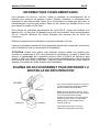
ADDITIONAL INFORMATION
To achieve the better results, use the tank cooling method to lower the head pressure
on the recovery tank. Repeat as necessary to achieve the desired vacuum level.
NOTE: If there is no liquid in the recovery tank, then the cooling method will not work. In
this case, use an empty tank that has been fully evacuated to achieve the final vacuum
level required.
To maximize recovery rates use the shortest possible length of 3/8” or larger hose. A
hose no longer than 1 meter (3 feet) is recommend. Always remove all unnecessary
hose core depressors and Schrader valves from port connections (using the proper
valve core tool) for maximum throughput. Deformed rubber seals and core depressors
in hoses and faulty or unnecessary Schrader valves can restrict flow by up to 90%.
If the tank pressure exceeds 31,5 bar (450PSI), use the tank cooling procedure to
reduce the tank pressure. When recovering large amounts of liquid, use the
“PUSH/PULL” method of recovery (see diagram below).
CAUTION: When using the “PUSH/PULL” method, you must use a scale to prevent
overfilling the storage tank. Once the “PUSH/PULL” siphon is started, it can continue
and overfill the storage tank even if the tank is equipped with a float level sensor. The
siphon can continue even when the machine is turned off. You must manually close the
valves on the tank and the unit to prevent overfilling the recovery tank.
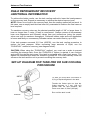
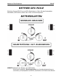
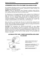
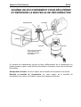
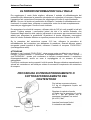
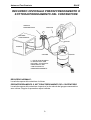
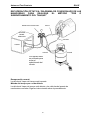
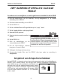
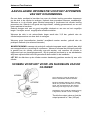
SET-UP DIAGRAM FOR TANK PRE OR SUB COOLING
PROCEDURE
INPUT
OUTPUT
VAPOR
LIQUID
To start you must have a minimum of
2,5 kg of liquid refrigerant in the tank.
Throttle the Outlet valve so that the
Outlet pressure is 7 bar (10
0 psi)
greater than the Inlet pressure, but
never more than 31,5 bar (450 psi).
Run until the tank is cold.
7

Advanced Test Products RG6-E
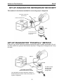
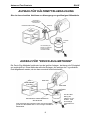
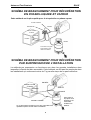
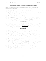
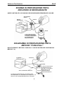
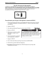
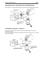
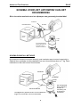
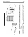
SET-UP DIAGRAM FOR REFRIGERANT RECOVERY
This method is the fastest method for recovering vapor refrigerant.
MANIFOLD GAUGE SET
(OPTIONAL) MOISTURE
SIGHT GLASS
INPUT
OUTPUT
LIQUID
A scale must be used
to avoid overfilling the
storage tank.
SYSTEM
BEING
SERVICED
VAPOR
LIQUID
SET-UP DIAGRAM FOR “PUSH/PULL” METHOD
Push pull only works with large systems where the liquid is readily accessible. Do not
use this method on systems that contain less than 7 Kilograms of refrigerant as it may
not work.
SYSTEM
BEING
SERVICED
LIQUID
VAPOR
VAPOR
LIQUID
OUTPUT
OPTIONAL MOISTURE
INDICATING SIGHT GLASS
INPUT
The sight glass is used to provide a method of
determining the moisture content and quality of a
system’s refrigerant.
A scale must be
used to avoid
overfilling the
storage tank.
8

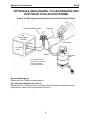
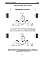
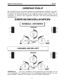
Advanced Test Products RG6-E
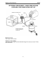
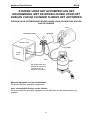
OPTIONAL RECOVERY / TANK PRE OR SUB
COOLING FOR FIXED HOSE SET UP
SYSTEM
BEING
SERVICED
LIQUID
VAPOR
VAPOR
LIQUID
MANIFOLD GAUGE SET
INPUT
OUTPUT
A scale must be used
to avoid overfilling the
storage tank.
Normal recovery:
Tank Vapor valve is closed.
Tank pre or sub cooling:
Tank Vapor valve is open and both Manifold Gauge Set valves are closed. Follow
above procedure.
9

Advanced Test Products RG6-E
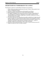
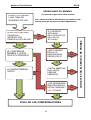
RG6-E RECOVERY
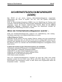
Purging the non-condensable gases from identified refrigerant in a tank
1. Allow the tank to sit undisturbed for 24 hours. (This allows the air to rise to the top).
2. Connect a manifold to the tank and read the amount of pressure in the tank by
looking at the Outlet pressure gauge.
3. Determine the ambient temperature in the room.
4. Refer to a Refrigerant pressure/temperature chart. Find the temperature on the chart
and look across to the corresponding pressure for the type of refrigerant in the tank.
Determine how that relates to the reading on the gauge.
5. If the pressure reading is higher than the pressure shown on the chart, very slowly
(so as not to cause turbulence inside the tank) crack open the vapor port valve.
Watch the pressure on the gauge decrease. To prevent venting, add 0,3 - 0,35 bar
(4 - 5 psi) to the pressure shown on the chart. When the gauge corresponds to that
pressure, close the vapor port valve.
6. Allow the tank to sit for 10 minutes and check the pressure again.
7. Repeat the process again if necessary.
10

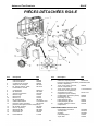
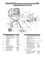
Advanced Test Products RG6-E
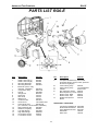
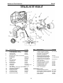
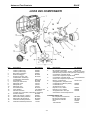
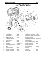
Pos.Description Part No.
1 Plastic case half (L) 550495
Plastic case half (R) 550496
2 Mounting Bushings 550503
3 Mounting brackets SK-6021
4 Motor Kit (motor, relay,
capacitor, hardware) SK-6018
5 Compressor Assy. 568114-E
6 Fan Kit SK-6008
7 Gauge lens GA1000
8 Red knob 100124
9 Blue knob 100123
10 Black knob 100122
11 Condensor Kit SK-6014
12 Power Cord 135-200341-001
13 Front Panel Assy. SK-6019-E
(incl. switches, circuit breaker, hardware)
14 Filter Inlet Repl. Kit SK-6001
15 Rubber Foot (each) 550502
16 Low Side Gauge SK-6003
17 High Side Gauge SK-6022
18 Hi Pressure Switch 549259
19 Lo Pressure switch 113726
PARTS LIST RG6-E
11
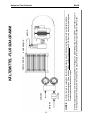
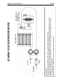
Pos. Description Part No.
A Complete Manifold Assy. SK-6016-E
(manifold, fittings, valves, knobs, pressure
sensors and gauges)
B Lower Tubing Assy. 550076
C Upper Tubing Assy. 110-201490-001
D Coupler 551917-KIT
E Run Capacitor (30mF) 556593
Start Capacitor (177mF) 553344
F Plastic Insert, Right 550501
Plastic Insert, Left 550500
G Molded Compressor 549758
Mount
ADDITIONAL PARTS/KITS
Compressor Rebuild Kit SK-6006
Piston Seal Rebuild Kit SK-6015
Valve Replacement Kit SK-6007
Filter/Drier 100343
Filter hose 100345

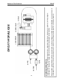
Advanced Test Products RG6-E
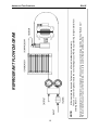
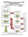
REFRIGERANT FLOW DIAGRAM
NOTE:
A filter must always be used. Failure to use a filter will invalidate your warranty.
The use of a filter will greatly reduce the risk of damage to your RG6
-E by preventing foreign material from
entering the unit.
Special consideration for filtration must be given when you know you are servicing a machine that has "Burned Out".
We recommend the use of two size 162 filter driers, in line, to be used for that job and that job only.
12

Advanced Test Products RG6-E
.SAFETY PRESSURE SWITCH
The RG6-E is equipped with an internal Safety Pressure Switch. If the pressure inside
the system exceeds 38,5 bar (550PSI), the system is switched off automatically.
If the Safety Pressure Switch is activated automatically whilst filling a bottle, it could be
caused by the bottle becoming overfilled.
This is a very dangerous situation! You should take steps immediately to reduce the
overpressure and/or to eliminate the overfilling of the bottle.
If the Safety Pressure Switch switches the unit off...
The following precautions should be taken if the Safety Pressure Switch is activated:
a) Suspected overfilling of the recovery bottle
Connect the recovery bottle to another bottle with spare capacity so that the pressure is
reduced to a safe level. This action should also reduce the pressure in the Outlet line
from the RG6-E. Proceed as normal after resetting the Safety Pressure Switch (see
below).
b) Cause of activation of Safety Pressure Switch unknown
1) Check that the recovery bottle is not overfilled.
2) Close the system valves, recovery bottle valves and RG6-E valves.
3) Disconnect RG6-E from flexible pipes.
4) Disconnect RG6-E from the power supply.
5) Open the Inlet and Outlet valves very slowly.
6) Investigate the reason for the failure.
Once activated the Safety Pressure Switch will remain ‘open’ until the pressure within
the system is reduced below 28 Bar (400PSI), at which time it will automatically reset. It
is not possible to operate the unit until this occurs.
13

Advanced Test Products RG6-E
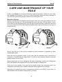
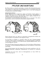
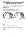
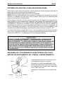
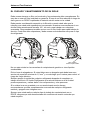
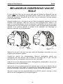
CARE AND MAINTENANCE OF YOUR
RG6-E
A filter must always be used and should be replaced frequently. Failure to use a filter
will invalidate your warranty. The use of a filter will greatly reduce the risk of damage to
your RG6-E by preventing foreign material from entering the unit.
Burned-out System
Special consideration for filtration must be given when you know the machine you are
servicing has "burned out". We recommend the use of two size 162 filter driers, in line,
to be used for that job and that job only. We also recommend that a clean filter be used
for every service job. Each filter should be labeled and used exclusively for one type of
refrigerant only.
Do not use this unit in the vicinity of spilled or open containers of gasoline or other
combustible liquids
Avoid the use of extension cords. If you must use an extension cord it should be a
minimum of 14 AWG and no longer than 7,5 m (25 ft). Not using an extension cord will
greatly reduce the risk of fire.
Always purge the unit of any refrigerant left after completing a service job. Refrigerant
left in the machine can expand and may cause damage to components.
If the unit is to be stored or not used for any length of time, we recommend that it be
completely evacuated of any residual refrigerant and purged with dry nitrogen.
Whenever you perform any type of maintenance work on your RG6-E, insure that it is
disconnected from the power supply before you begin.
14
&)')&)$!%))!)%+)&-)0#.0*!%*'+%#%+ !#+)*)%!%+ !%#+!++!%
&%+ ,%!+'#+ !#+)*)%'% !%**)0!#+)*)%)+#0),*+
)!*"&$+&+ ,%!+0')-%+!%&)!%$+)!#)&$%+)!%+ ,%!+%+ *0*+$!%
*)-!!#,)+&,*!#+)*)%.!##!%-#!++ .))%+0
&!%!)#*&*+)&%#0)&$$%*,*!%%!%#!%!#+))!)'%!%+ !%#+#!%
*+.& ! !'!+04#+))!)*!%*)!*. %)&-)!%)&$1,)%&,+2*0*+$&!%!)
)&$$%*#&+0'&)'&)#%+0'4#+)*
%0&, -4%!* )&-)!%)&$+ *0*+$5,* + ,%!+.!+ *$##$&,%+&#%
$'+0))!)%+)&$+ ,%!+!%+&*+&)0#!%)!(,!))!)%+#+!%+ ,%!+3*&%%*)$0
/'%,*!%$+&&$'&%%+*
&$'#+#0-,++ ,%!+&%0)*!,#))!)%+%',)!+.!+ )0%!+)&%&)',++!%!+
Filter
Screen
Inlet
Fitting Filter /Drier
p/n 100343

Advanced Test Products RG6-E
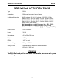
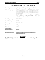
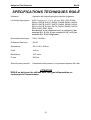
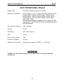
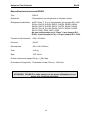
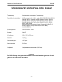
TECHNICAL SPECIFICATIONS
Type RG6-E
Application Refrigerant recovery Gas or Vapor
Suitable refrigerants AHRI Category III, IV & V such as: R12, R22, R134A,
R401A, R401B, R401C, R402A, R402B, R404A, R406A,
R407A, R407B, R407C, R407D, R408A, R409A, R410A,
R411A, R411B, R412A, R417A, R422A, R422D, R427A,
R500, R502, R507, R509
Not intended for use with Category I (e.g. R11, R123),
Not intended for use with Category II (e.g. R114)
Not intended for use with Category nor VI (e.g. R13, R23)
Power Source 230V / 50-60Hz
Power 3/4 HP
Dimensions 430 x 230 x 305 mm
Weight 14,5 kg
RPM´s 1437 rev./min
Max. working pressure 550 p.s.i. (38,5 bar)
Safety Device Safety pressure switch with Automatic reset
(550 p.s.i. / 38,5 bar)
ATTENTION
The RG6-E should not be used with inflammable gases nor with gases
containing ammonia.
15

Advanced Test Products RG6-E
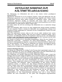
HELPFUL HINTS FOR REFRIGERANT
RECOVERY
Refrigerant recovery has come a long way in a few short years.
On the surface it’s simply the process of taking refrigerant out of a system and putting it
into a tank. However, this simple process can quickly become problematic if a few items
are overlooked. The following are some tips and pointers we’ve accumulated over the
last few years that can save you time and make the process go smoother.
First you need to identify the refrigerant type and quantity in the system you are
servicing.
If you determine it’s a burnout, you need a special tank (a tank that’s identified as
containing burnout or other unidentified gases), and you need to use extra filtration prior
to recovery.
If, on the other hand, you know the gas in the system is relatively clean or new, then a
new tank should be used. If you’re planning on putting the refrigerant back into the
same system after you have finished the service or if the refrigerant is going to be
reclaimed, then use a tank that has the same refrigerant in it. A word of caution about
the Environmental Protection Agency (EPA): If you use a variety of refrigerant gasses in
your service work - as evidenced by your refrigerant purchases - and you only own one
tank, you are asking for trouble. You would be well advised to own at least one tank for
every refrigerant type serviced, plus an extra for burnouts and other unknowns.
Planning Ahead
Knowing the quantity of refrigerant is important for planning storage requirements, as
well as planning for the actual recovery. For instance, any system with more than 5lbs.
of refrigerant is likely to have areas where the liquid can get trapped.
The key to a quick recovery procedure is to get the liquid out first, and then get the
remaining vapor out. However most systems are not “recovery friendly.” That is they
don’t have access ports at their lowest points. If some units you’re servicing are on
maintenance contracts, you would save significant time by installing access ports at all
of the lowest points in the system, where liquid is likely to accumulate. Since most
systems don’t have these ports you need to be prepared to boil of the trapped liquid
with a heat gun, whenever it’s found. An indicator of trapped liquid in a system is frost or
condensation forming on the plumbing or components where the liquid is trapped. The
trapped liquid may be in an area that is not visible. In all cases trapped liquid in a
system during recovery causes the recovery process to slow down, regardless of the
size or type of machine
If you are unable to locate the trapped liquid (but you know it’s there, because the
recovery job is taking “forever”), turn on the system compressor (if it’s operable) for a
few seconds. This will get the refrigerant moving to another part of the system and in.
16

Advanced Test Products RG6-E
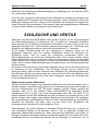
HOSES AND VALVES
Hoses and Schraeder valves have a large impact on recovery speed. In general, the
larger the hose, the less friction on the flow of refrigerant and the quicker the recovery
time. Many contractors are now using 3/8” lines for the Inlet to the recovery machine,
even if those lines originate out of 1/4” fittings.
Schraeder valves must be removed from the connection prior to an expedient
recovery. Most wholesalers sell a tool for removing these cores, while keeping the
connection sealed. The core depressor, in the end of the hose, should also be removed.
These two items can turn a 20 minute job into one that goes on for hours. So, be sure to
remove Schraeder valves and core depressors before every recovery job.
Another hose consideration is the little rubber grommet at the end of the hose that
makes a seal with the flare fitting. We’ve seen these seals so worm and deformed that
when the hose is connected to the flare fitting the grommet virtually seals off the
connection. This is probably never noticed in charging, because the pressure opens the
grommet, but during recovery (or with suction) the deformed grommet severely restricts
the flow of refrigerant.
Refrigerant Recycling
Current regulations state that used refrigerant shall not be sold, or used in a different
owner’s equipment, unless the refrigerant has been laboratory analyzed and found to
meet the requirements of ARI 700 (latest edition). As a result, recycling and verifying
ARI 700 conformance isn’t economically justified in most cases. It’s still a great idea to
do as much cleaning of refrigerant going back into the same system (or owners
system) as possible. We recommend using the largest, high-acid capacity filter that are
economically feasible. Put these filters on the suction or inlet side of the recovery unit.
Change filters often.
The recovery of large amounts of liquid refrigerant can sometimes carry with it large
quantities of oil, if the system being serviced doesn’t have an adequate oil separator
installed. If this recovered refrigerant isn’t going to be liquid charged back into the same
system, you might want to separate the refrigerant from the oil in order to
measure the oil (to know how much oil to charge back into the system). However
refrigerant sent back for reclaim does not need to have the oil removed. One of the
simplest and most cost effective ways to achieve this is to use a 30 or 50 lb. tank in line
with your recovery machine. Connect the system to the liquid port of the tank then from
the vapor port of the tank connect to the Inlet of your recovery machine a second tank,
for storing refrigerant, should then be connected to the Outlet of the recovery machine.
If you encounter large amounts of liquid you will need to put a band heater around the
first tank.
When the recovery job is complete the oil can be removed, from the first tank, by
applying a small amount of pressure, using nitrogen, to one of the ports and expressing
the oil from the other. If you are going to remove the oil from the vapor port you will
need to turn the tank upside down. Always wear safety glasses when performing this
operation as the oil may be acidic and could cause severe burning.
17

Advanced Test Products RG6-E
KEEPING THE DIRT OUT
During the recovery process your recovery machine can be exposed to debris that can,
potentially, damage it. Including brazing spatter and copper and brass slithers. Further
contamination can be introduced from the refrigerant storage tanks. To prolong the life
of your recovery machine always use an in-line filter.
Whenever you are charging a system from a recovery cylinder it is a good idea to use
an in-line filter to protect the system from contamination. Again, change your in-line
filters often.
Getting the Liquid Out (See “Push/Pull-Method”)
Push-pull is a method of removing bulk liquid from a system using the pressure
differential created by the recovery machine. Push-pull will generally not work on
smaller systems because there is no bulk liquid reservoir to create a siphon from.
Push-pull is mostly used on systems with a receiver tank or those with greater than 20
lbs. of refrigerant, or when transferring from one tank to another. The rate of liquid
transfer id very much dependent on hose size, with larger hoses providing much
better throughput.
Another trick is to chill the tank, if it’s partially filled, prior or during recovery. This
operation will lower the pressure in the storage tank and therefore speed up recovery.
There must be a minimum of 5 lbs of liquid refrigerant in the tank you wish to chill. This
operation can be performed prior to or during the recovery. See the two set up diagrams
and procedures on page 8 of this manual.
There is nothing magic here, you are simply using your recovery machine to make a
refrigerator where the tank is the evaporator. By throttling the Outlet valve, you’re
effectively creating a capillary tube or an expansion device, but you need to adjust the
back pressure to suit the conditions and the refrigerant. Five to ten minutes of chilling
can produce some very dramatic tank cooling, depending on the conditions. If there are
any non condensable in the tank this process will not work. Also the greater the quantity
of refrigerant in the tank the longer the process will take.
18
Seite wird geladen ...
Seite wird geladen ...
Seite wird geladen ...
Seite wird geladen ...
Seite wird geladen ...
Seite wird geladen ...
Seite wird geladen ...
Seite wird geladen ...
Seite wird geladen ...
Seite wird geladen ...
Seite wird geladen ...
Seite wird geladen ...
Seite wird geladen ...
Seite wird geladen ...
Seite wird geladen ...
Seite wird geladen ...
Seite wird geladen ...
Seite wird geladen ...
Seite wird geladen ...
Seite wird geladen ...
Seite wird geladen ...
Seite wird geladen ...
Seite wird geladen ...
Seite wird geladen ...
Seite wird geladen ...
Seite wird geladen ...
Seite wird geladen ...
Seite wird geladen ...
Seite wird geladen ...
Seite wird geladen ...
Seite wird geladen ...
Seite wird geladen ...
Seite wird geladen ...
Seite wird geladen ...
Seite wird geladen ...
Seite wird geladen ...
Seite wird geladen ...
Seite wird geladen ...
Seite wird geladen ...
Seite wird geladen ...
Seite wird geladen ...
Seite wird geladen ...
Seite wird geladen ...
Seite wird geladen ...
Seite wird geladen ...
Seite wird geladen ...
Seite wird geladen ...
Seite wird geladen ...
Seite wird geladen ...
Seite wird geladen ...
Seite wird geladen ...
Seite wird geladen ...
Seite wird geladen ...
Seite wird geladen ...
Seite wird geladen ...
Seite wird geladen ...
Seite wird geladen ...
Seite wird geladen ...
Seite wird geladen ...
Seite wird geladen ...
Seite wird geladen ...
Seite wird geladen ...
Seite wird geladen ...
Seite wird geladen ...
Seite wird geladen ...
Seite wird geladen ...
Seite wird geladen ...
Seite wird geladen ...
Seite wird geladen ...
Seite wird geladen ...
Seite wird geladen ...
Seite wird geladen ...
Seite wird geladen ...
Seite wird geladen ...
Seite wird geladen ...
Seite wird geladen ...
Seite wird geladen ...
Seite wird geladen ...
Seite wird geladen ...
Seite wird geladen ...
Seite wird geladen ...
Seite wird geladen ...
Seite wird geladen ...
Seite wird geladen ...
Seite wird geladen ...
Seite wird geladen ...
Seite wird geladen ...
Seite wird geladen ...
Seite wird geladen ...
Seite wird geladen ...
Seite wird geladen ...
Seite wird geladen ...
Seite wird geladen ...
Seite wird geladen ...
Seite wird geladen ...
Seite wird geladen ...
Seite wird geladen ...
Seite wird geladen ...
Seite wird geladen ...
Seite wird geladen ...
Seite wird geladen ...
Seite wird geladen ...
Seite wird geladen ...
Seite wird geladen ...
Seite wird geladen ...
Seite wird geladen ...
Seite wird geladen ...
Seite wird geladen ...
Seite wird geladen ...
-
 1
1
-
 2
2
-
 3
3
-
 4
4
-
 5
5
-
 6
6
-
 7
7
-
 8
8
-
 9
9
-
 10
10
-
 11
11
-
 12
12
-
 13
13
-
 14
14
-
 15
15
-
 16
16
-
 17
17
-
 18
18
-
 19
19
-
 20
20
-
 21
21
-
 22
22
-
 23
23
-
 24
24
-
 25
25
-
 26
26
-
 27
27
-
 28
28
-
 29
29
-
 30
30
-
 31
31
-
 32
32
-
 33
33
-
 34
34
-
 35
35
-
 36
36
-
 37
37
-
 38
38
-
 39
39
-
 40
40
-
 41
41
-
 42
42
-
 43
43
-
 44
44
-
 45
45
-
 46
46
-
 47
47
-
 48
48
-
 49
49
-
 50
50
-
 51
51
-
 52
52
-
 53
53
-
 54
54
-
 55
55
-
 56
56
-
 57
57
-
 58
58
-
 59
59
-
 60
60
-
 61
61
-
 62
62
-
 63
63
-
 64
64
-
 65
65
-
 66
66
-
 67
67
-
 68
68
-
 69
69
-
 70
70
-
 71
71
-
 72
72
-
 73
73
-
 74
74
-
 75
75
-
 76
76
-
 77
77
-
 78
78
-
 79
79
-
 80
80
-
 81
81
-
 82
82
-
 83
83
-
 84
84
-
 85
85
-
 86
86
-
 87
87
-
 88
88
-
 89
89
-
 90
90
-
 91
91
-
 92
92
-
 93
93
-
 94
94
-
 95
95
-
 96
96
-
 97
97
-
 98
98
-
 99
99
-
 100
100
-
 101
101
-
 102
102
-
 103
103
-
 104
104
-
 105
105
-
 106
106
-
 107
107
-
 108
108
-
 109
109
-
 110
110
-
 111
111
-
 112
112
-
 113
113
-
 114
114
-
 115
115
-
 116
116
-
 117
117
-
 118
118
-
 119
119
-
 120
120
-
 121
121
-
 122
122
-
 123
123
-
 124
124
-
 125
125
-
 126
126
-
 127
127
-
 128
128
-
 129
129


in anderen Sprachen
- français: Promax RG6-E-230V Manuel utilisateur
- español: Promax RG6-E-230V Manual de usuario
- italiano: Promax RG6-E-230V Manuale utente
- Nederlands: Promax RG6-E-230V Handleiding
Verwandte Artikel
Andere Dokumente
-
Bosch Minimax-E Benutzerhandbuch
-
Bosch RG8.0 Bedienungsanleitung
-
Rothenberger Refrigerant recovery device ROREC Pro Benutzerhandbuch
-
Matrix R1xe Bedienungsanleitung
-
Cambridge Audio Incognito Benutzerhandbuch
-
Abus TVHD40000 Benutzerhandbuch
-
Abus TVHD50000 Benutzerhandbuch
-
-
Strong SLIMSAT SA61 Benutzerhandbuch
-
MasterCool R11 Benutzerhandbuch