
FR
EN
DE
IT
ES
General purpose
immersion thermostats,
baths & circulators
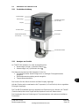
Optima T100 & TC120
Operating Manual

Grant Instruments, based near Cambridge, England is a world leader in the
manufacture and design of equipment for sample preparation, scientific analysis, data
acquisition and data analysis providing solutions to the global scientific and industrial
markets.
Standards Compliance and Quality
Grants’ brand and reputation are based around quality, reliability and accuracy. We
ensure our products stringently meet all necessary international safety standards.
We pay particular attention to the safety testing of products and remain at the forefront of
the product safety standard for laboratory equipment IEC 61010-1. The company is
committed to operating its safety test laboratory in accordance with the requirements of
ISO 17025.
Grant operates a Quality Management System that complies with the requirements of BS
EN ISO 9001:2008.
Beyond compliance to the standard, Grant is committed to continually improving in
everything we do; with particular emphasis on understanding what matters to our
customers and suppliers, and designing our systems and work to meet their needs.
If you have any feedback on Grant’s products or services we would like to hear from you.
Please send all feedback to:
Quality Manager
Grant Instruments (Cambridge) Ltd
Shepreth
Cambridgeshire
SG8 6GB
UK
Tel: +44 (0) 1763 260 811
Fax: +44 (0) 1763 262 410
E-mail: feedback@grantinstruments.com

T100 & TC120 30423 V4
Operating Manual Page 2
www.grantinstruments.com
EN
Contents
Contents 2
1.0 Use of products 4
2.0 How to use this operating manual 4
3.0 Safety information 5
3.1 Safety compliance 5
3.2 Safety symbols 5
3.3 Safety warnings 5
4.0 Operating instructions 6
4.1 Unpacking instructions 6
4.2 Fitting controller to ST baths 6
4.3 Fitting the controller to P baths 7
4.4 Fitting the controller to custom baths 7
4.5 Removing the controller from the bridge plate 8
4.6 Recommended liquids 8
4.7 Installation 9
4.8 Electrical supply 9
4.9 Using accessory cooling (C1G, C2G, CW5) 9
5.0 Operating procedures 10
5.1 Operation 10
5.1.1 Liquid level 10
5.1.2 Operation above 60°C 10
5.1.3 Operation at low temperatures 10
5.1.4 Using the pump (TC120 only) 10
5.1.5 Emptying the ST baths 11
5.1.6 Setting up and switching on 11
5.2 Using the T100 & TC120 12
5.2.1 Product description 12
5.2.2 Product indicators 12
5.2.3 Setting the control temperature 13
5.2.4 Configuring a preset 13
5.2.5 Running a bath preset 13
5.2.6 Completing a calibration 14
5.2.7 Restoring factory calibration settings 15
5.2.8 Adjusting display brightness 15
5.3 Additional features of the TC120 16
5.3.1 Setting the over-temperature thermostat 16
5.3.2 Setting a countdown timer 16
5.3.3 Cancelling the timer 17
5.3.4 Setting a high temperature warning alarm 17
5.3.5 Selecting liquid type 17
6.0 Technical specifications 18
6.1 Operating conditions 18
6.2 Electrical details 18
6.3 Product performance 18
6.4 Bath accessories information 18
7.0 Technical Tips 19
7.1 Which water should you use in your bath? 19
7.2 How to prevent rust in water baths 19
7.3 How to prevent algae and bacteria? 19
8.0 Warranty information 20
9.0 Maintenance and service 20
9.1 Routine Maintenance 20
9.2 Cleaning 20


T100 & TC120 30423 V4
Operating Manual Page 4
www.grantinstruments.com
EN
1.0 Use of products
The following products are covered by this operating manual:
T100 & T100L
TC120 & TC120L
The products listed above are general purpose immersion thermostats to be used with
baths or circulators designed for indoor laboratory use by a professional user.
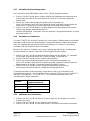
2.0 How to use this operating manual
This operating manual will allow you to unpack, set-up and operate this immersion
thermostat correctly and safely. Important safety information, symbols and warnings are
listed below and should be read carefully. Section 4 gives information about how to
unpack and install the product correctly. Section 5 gives operating information for the
T100 & TC120 models. Product technical specifications and tips are provided in sections
6 and 7. The warranty for this product is for THREE YEARS and is detailed in section 8
and should be registered by completing the on-line registration form at
www.grantinstruments.com.
If there is a technical matter that this operating manual does not address, or any other
question concerning this product, please contact Grant Instruments or your local
distributor, who will be able to provide any additional information.
A quick start guide is provided with the T100/TC120 immersion thermostats as a
reference guide but should not be used until the full user manual has been read.

30423 V4 T100 & TC120
Page 5 Operating Manual
www.grantinstruments.com
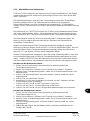
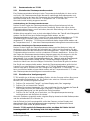
3.0 Safety information
3.1 Safety compliance
Grant immersion thermostats meet the requirements of international safety standard
IEC 61010: Safety requirements for electrical equipment for measurement, control, and
laboratory use. They also comply with the equivalent national standards including:
EN 61010-2-010
UL 61010A-2-010
CAN/CSA-C22.2 NO. 61010-2-010-04.
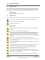
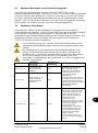
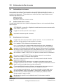
3.2 Safety symbols
The symbols below are marked on the equipment and throughout this manual to indicate:
Caution: Surfaces and heat transfer liquid can be hot during and after use.
Read this manual before using the bath.
Important safety warning.
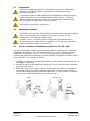
3.3 Safety warnings
Read the whole of these instructions. Safety may be impaired if they are not
followed.
For the T100, only use water as the working liquid.
For the TC120, only use liquids specified in these operating instructions, within
the specified temperature range. If the alarm lamp is illuminated the liquid
temperature may be above its recommended maximum. Do not inhale the
vapours given off as they may be toxic. Liquids should be safely discarded and
replaced.
Do not use the T100/TC120 with flammable heat transfer liquids.
Do not use the T100/TC120 to heat any sample material that could cause a fire
or any other kind of hazard.
Do not use the equipment in an area where there are aggressive or explosive
chemical mixtures.
If a potentially hazardous liquid is spilt onto or inside the equipment, disconnect
it from the power supply and have it checked by a competent person.
It is the user’s responsibility to carry out appropriate decontamination if
hazardous material is spilt on the equipment.
If the alarm lamp is illuminated do not touch the liquid or the tank base, they
may be very hot. Refill carefully, a hot heater can cause a spattering of very hot
water droplets and scalding steam.
Do not touch surfaces which become hot during high temperature operation.

T100 & TC120 30423 V4
Operating Manual Page 6
www.grantinstruments.com
EN
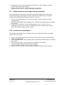
4.0 Operating instructions
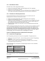
4.1 Unpacking instructions
Standard equipment includes:
Immersion thermostat (T100 or TC120)
Pump outlet plates (TC120 only)
Mains cord with plug
Operating manual
Quick start guide
ST bath accessory includes:
Stainless steel bath
Bridge plate
Circulating tray (ST18, ST26 & ST38 baths only)
P bath accessory includes:
Plastic bath
Bridge plate
Remove packing materials carefully and retain them for future shipment or storage of the
equipment.
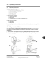
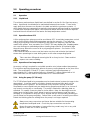
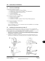
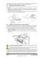
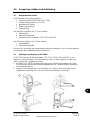
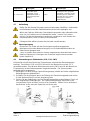
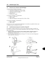
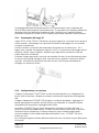
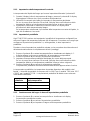
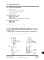
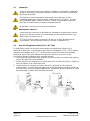
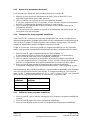
4.2 Fitting controller to ST baths
The T100/TC120 can be fitted to the following stainless steel baths, ST5, ST12, ST18,
ST26 and ST38 in two orientations for convenience, facing over ST bath (A) or facing
outwards (B):
1. Fit the T100/TC120 through the hole in the bridge plate and align using the locating
threads. Secure using the retaining nuts. Hand tighten only.
2. Hook the assembly into the slots on the ST bath and use the supplied fixing to secure
to the rear of the bath.
2
A
B
1
2

30423 V4 T100 & TC120
Page 7 Operating Manual
www.grantinstruments.com
Fit the circulation tray in the base of the tank with the large cut out in the tray underneath
the control unit (ST18, ST26 & ST38 only).
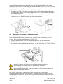
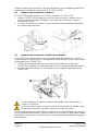
4.3 Fitting the controller to P baths
The T100/TC120 can be fitted to the following plastic baths, P5, P12 and P18:
1. Fit the T100/TC120 through the hole in the bridge plate and align using the locating
threads. Secure using the retaining nuts. Hand tighten only.
2. Add the assembly to the P bath and use the supplied fixing to secure to the rear of
the bath.
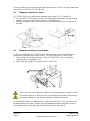
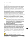
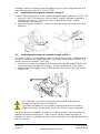
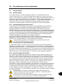
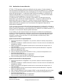
4.4 Fitting the controller to custom baths
A clamp can be fitted to the T100/TC120 to allow attachment to a non-Grant bath or
vessel with a wall thickness of up to 30mm. To fit the clamp to the T100/TC120:
1. Place clamp over locating threads on base of T100/TC120. Secure using the
retaining nuts. Hand tighten only.
2. Add clamp rear fixings to secure to rear of T100/TC120.
Take care not to over tighten the clamp to avoid damaging the clamp or vessel
The liquid container on which the unit is mounted must be stable and have the
necessary robustness, mechanical, chemical and heat resistance.
Do not wash the clamp in a dishwasher or clean it with descaler. Do not submerse the
threaded shaft of the clamp. Always dry the threaded shaft and clamp after cleaning.
The threads may be lubricated with a small amount of light machine oil.
1
2
1
2

T100 & TC120 30423 V4
Operating Manual Page 8
www.grantinstruments.com
EN
4.5 Removing the controller from the bridge plate
Allow the working liquid to cool before removing the T100/TC120 from the bridge plate.
Carefully remove the T100/TC120 and bridge plate together from the bath or vessel.
Take care as the pump will contain a small amount of the working liquid which will leak
out as the unit is handled. Undo the retaining nuts and remove the bridge plate. Attach
the retaining nuts to the locating threads for safe keeping.
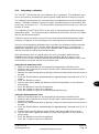
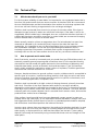
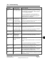
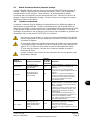
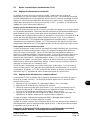
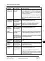
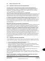
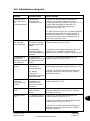
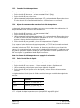
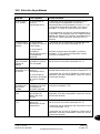
4.6 Recommended liquids
The following table lists the recommended liquids for different temperature ranges.
Always ensure the liquid used is safe and suitable for your working temperature. If using
non-recommended heat transfer liquids, it is the responsibility of the user to conduct an
assessment to ensure the intended fluid is compatible with the T100/TC120 and vessel.
If using non-recommended heat transfer liquids it is important to set the over-temperature
cut-out to a value no higher than 25°C below the fire point of the liquid. If in doubt please
contact the Grant technical support team.
To ensure protection the overtemperature cut out (TC120 only) must be set
appropriately for the heat transfer liquid selected. See table below.
If using non-recommended heat transfer liquids it is important to set the over-
temperature cut-out to a value no higher than 25°C below the fire point of the
liquid. If in doubt please contact the Grant technical support team.
Use fume extraction when using silicone fliuids at elevated temperatures
Temp range
Recommended
liquid
Cut-out
setting
Comments
-30°C to 30°C
50% water, 50%
antifreeze (inhibited
ethylene glycol)
40°C
WARNING: Ethylene glycol is
toxic – follow the manufacturer’s
instructions.
For safe disposal consult your
local regulations.
Use a lid to reduce the dilution
of the mixture caused by
condensing water vapour from
the air, and to maintain the cool
down rate.
0°C to 30°C
80% water, 20%
antifreeze (inhibited
ethylene glycol)
40°C
5°C to 99.9°C
Water*
110°C
Water can be used but care
should be taken above 60°C as
hot vapour can be dangerous.
Use a lid or polypropylene
spheres above 60°C to ensure
good performance & reduce
evaporation.
At temperatures approaching
99°C the temperature
performance will be affected due
to localised boiling.
The units should not be used to
boil water.

30423 V4 T100 & TC120
Page 9 Operating Manual
www.grantinstruments.com
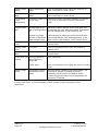
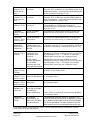
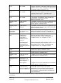
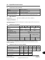
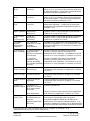
Temp range
Recommended
liquid
Cut-out
setting
Comments
70°C to 120°C
Silicone fluid
Viscosity ~20cs
Flash point ≥230°C
Fire Point ≥280°C
130°C
Dow Corning DC200/20 silicone
fluid is a suitable liquid – follow
the manufacturer’s instructions.
For safe disposal consult your
local regulations.
* See section 7.1 for further details
4.7 Installation
Place the water bath on a level, non-combustible surface. Ensure that the
mains plug and the switch at the rear of the unit are easily accessible.
If the equipment has been transported or stored in cold or humid conditions,
condensation may form inside it. If that could have happened, allow time (at
least 2 hours at room temperature) for the condensation to evaporate before
using the equipment.
Do not block or restrict ventilation slots.
4.8 Electrical supply
Check that the supply voltage marked on the serial number label, and the type
of mains plug, are correct for your mains supply outlet, which must have a
ground connector.
The T100/TC120 must only be connected to the mains using the mains cord
supplied or one with an identical rating (see section 9.4)
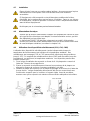
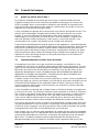
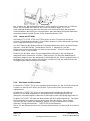
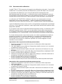
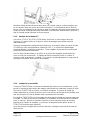
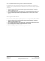
4.9 Using accessory cooling (C1G, C2G, CW5)
Accessory cooling is required for operation at temperatures below ambient. Refrigerated
dip coolers (C1G and C2G) can be used for operation down to -15°C. A water heat
exchanger coil (CW5) can be used for operation at or around ambient. The coils can be
fitted:
1. Attach u-shaped coil locating rod to cover plate using two fixings supplied.
2. Fit the cooling coil through the hole in the bridge plate and align outlet pipes with cut-
out notch.
3. Fit cover plate onto bridge plate and attach with fixings supplied. The coil locating
rod should press fit against the inside of the coil and hold it rigidly. Ensure the coil is
held safely and securely before operation.
2
1
3
CW5
C1G & C2G
2
1
3

T100 & TC120 30423 V4
Operating Manual Page 10
www.grantinstruments.com
EN
5.0 Operating procedures
5.1 Operation
5.1.1 Liquid level
The minimum and maximum liquid levels are defined in section 6.4 for Grant accessory
baths. Liquid level should always be maintained between these levels. These levels
apply both when there are no vessels in the bath and with the maximum contents. If
using liquids that can evaporate then periodic checking and refilling should be completed.
The low level float switch will alarm if the liquid level drops below the minimum required
level and the unit will switch off the heater and stop temperature control.
5.1.2 Operation above 60°C
A lid or polypropylene spheres must be used above 60°C to maintain temperature control
and to ensure that the bath fluid temperature reaches the set point. They will save
energy by preventing excessive evaporation and reduce the frequency that the bath
needs to be refilled. As a precaution, the T100/TC120 may display ‘Hot’ if heating water
at or near boiling over extended periods or heating large volumes of liquid with large
thermal losses without the use of a lid or polypropylene spheres. See section 11 for
additional guidance.
Care should be taken to ensure rear inlet vents are clear and minimise the intake of
steam when operating at or near boiling water or with other evaporating liquids.
Take care when lifting and removing the lid as it may be hot. Steam and hot
vapours can cause scalding.
5.1.3 Operation at low temperatures
Accessory cooling is required for controlled operation at or below ambient temperature.
The minimum working temperature without accessory cooling depends on the size of the
bath. The small baths, P5 and ST5, have a minimum working temperature of
approximately 10°C above ambient without a lid and 15°C above ambient with a lid.
Other bath sizes can be used at a temperature of 5°C above ambient.
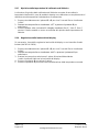
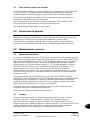
5.1.4 Using the pump (TC120 only)
The TC120 allows liquid to be pumped around a closed external system (not open to the
atmosphere). It may be used for circulation through an external open tank only if a
gravity feed return is present. An assessment of any reservoir running should be
completed to ensure liquid levels are stable during operation and there is no chance of
any resevoir running dry or overflowing. The pump is fitted with a blanking plate as
standard. Fit a pump connector plate as shown below. Note: the blanking/connector
plates have a locating hole (see A below) to assist correct alignment onto the pump
moulding. It is important to verify the hole is aligned with the corresponding locating pin
(see B below) on the pump moulding. Failure to do so will result in a leaking connection.
Retain the blanking plate for refitting when the pump is no longer required.
Always use pump connectors and hoses that are suitable for the operating
temperature and liquid used. Check the pipe connections are secure.
Never disconnect any pipes or hoses while they contain very hot or very cold
liquids or while the TC120 is pumping.

30423 V4 T100 & TC120
Page 11 Operating Manual
www.grantinstruments.com
Pumping heat transfer liquid around an external system can lead to hazards that are
outside the control of Grant Instruments. It is essential that the user conducts a risk
assessment of the entire equipment installation to ensure that correctly rated materials
have been used throughout and that the system can be used safely.
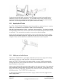
5.1.5 Emptying the ST baths
The ST12, ST18, ST26 & ST38 baths should be emptied to a safe level prior to moving.
A drain tap is included on these baths to allow convenient emptying.
Allow the liquid temperature to fall to a safe level before emptying. If the bath is drained
at temperatures above 50°C then the drain mechanism will be damaged and will need to
be replaced. Take reasonable precautions to prevent accidental spillage.
Empty the bath by pushing the supplied drain insert into the drain tap as shown below.
Note that the bath liquid will begin to empty as soon as the drain insert is fully engaged.
A length of hose can be added to the barbed end of the drain insert if required.
5.1.6 Setting up and switching on
Connect the T100/TC120 to a grounded (earthed) electrical power supply with voltage
and frequency within the range specified on the serial number plate.
Attach the T100/TC120 securely to the required bath or vessel. Add the appropriate
working liquid to the bath to at least the minimum recommended fill level such that the
float level switch is fully raised.
Switch on the T100/TC120 using the power switch on the rear of the unit. The motor will
start immediately and the buzzer will sound while the unit starts up. During start up the
display will show the model type, followed by the software version and finally the current
liquid temperature. The T100/TC120 is ready to use.
To disconnect the equipment from the mains supply, remove the mains plug from the
mains supply outlet.
B
A

T100 & TC120 30423 V4
Operating Manual Page 12
www.grantinstruments.com
EN
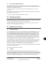
5.2 Using the T100 & TC120
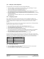
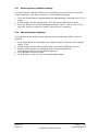
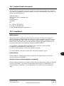
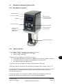
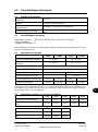
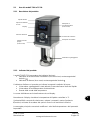
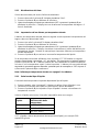
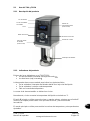
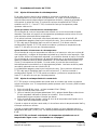
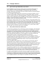
5.2.1 Product description
5.2.2 Product indicators
There are two indicator lights on the T100/TC120:
Heater on light (orange) marked
Alarm light (red) marked
The alarm lamp will light to indicate the following faults:
Float switch has operated due to low liquid level
Over-temperature cut out has operated
Temperature probe fault
The cause of the alarm will also be shown on the display.
The display normally shows the temperature in °C of liquid being controlled.
The S(elect) button is used to select and store values whilst the F(unction) button is used
to access menu options and cancel functions.
The main dial is used to change temperature values and other settable parameters.
Float switch
Display
Alarm light
Control dial
Heater on light
Pump outlet plate
(TC120 only)
Over-temperature dial
(TC120 only)
Select button
Function button

30423 V4 T100 & TC120
Page 13 Operating Manual
www.grantinstruments.com
5.2.3 Setting the control temperature
The temperature of the bath liquid can be set using the S button.
1. Whilst the display is showing the bath temperature, press the S button. This will
cause the display to flash indicating that it can be set.
2. Use the main dial to set the desired temperature.
If no key is pressed for 10 seconds then the display will revert back to showing the
bath temperature and the set temperature will remain at its original value.
3. Press the S button to store the requested value and the display will revert to showing
the bath temperature.
If the temperature selected is higher than the current liquid temperature, the heater
light will come on.
5.2.4 Configuring a preset
Each T100/TC120 contains three presets which can be configured to different set
temperatures to allow the bath to be conveniently run at frequently used temperatures.
Use the method below to configure preset 1; other presets can be set in a similar
manner.
Be aware that once a preset has been saved using the steps below, it will automatically
start once all the steps have been completed.
1. Press the F button and rotate the dial until the display shows “t-1”.
The display will alternate between the preset number and its temperature.
2. Press the S button to select the preset.
3. Use the dial to set the desired preset temperature.
If no key is pressed for 10 seconds then the display will revert back to showing the
bath temperature and the preset temperature will remain at its original value.
4. Press the S button to save the preset temperature.
The preset will automatically start as soon as the value is saved.
Preset temperatures and set temperatures are limited to the model type and the liquid
selection. The T100 settable range is between 0 and 100°C increasing to between -25°C
and 120°C for the TC120. The factory preset settings are shown in the table below.
Preset
Set temperature range
t-1
37°C
t-2
56°C
t-3
72°C
5.2.5 Running a bath preset
1. Press the F button and rotate the dial until the display shows the correct preset.
2. Press the S button to select the preset.
3. Press the S button to set the bath to the preset temperature.

T100 & TC120 30423 V4
Operating Manual Page 14
www.grantinstruments.com
EN
5.2.6 Completing a calibration
The T100 & TC120 allow a two point calibration to be completed. The calibration menu
can be accessed by simultaneously pressing the F and S buttons for about 5 seconds.
The calibration temperatures are constrained by the temperature limits of the liquid type
setting. Calibration should be carried out using a traceable reference thermometer with
an accuracy of at least 0.1°C. This thermometer should be held securely in the centre of
the bath or vessel.
The calibration of the T100/TC120 is in two parts, a low temperature offset and a high
temperature offset. The high temperature calibration point must be at least 40°C higher
than the low temperature point.
Calibration points should be chosen to be at critical experimental temperatures where
accuracy is important or at the extremes of the working range of used temperatures.
If only the low temperature calibration point is set then the calibration will be performed
between this point and 100°C with the offset decreasingly linearly. If only the high
temperature calibration point is set then the calibration will be performed between 0°C
and this point with the offset decreasingly linearly.
If the thermometer value is entered before the unit is completely stable then the
calibration could be poor and liquid temperature readings will be incorrect. If the
T100/TC120 is not in accordance with the thermometer following calibration then it may
not have been successful and the unit should be reset.
Setting the low temperature offset
1. Adjust the set temperature to the required low temperature calibration point.
2. Allow the unit to stabilise for at least 5 minutes after a stable temperature condition
has been achieved.
3. Measure the liquid temperature by placing a reference thermometer into the centre of
the bath.
4. Press the F and S buttons simultaneously for approximately 5 seconds until “LCAL” is
shown.
5. Press the S button to select.
6. Use the main dial to update the display to show the temperature on the reference
thermometer.
7. Press the S button to store the temperature.
Press the F button to cancel the calibration.
8. Press the F button to return to the liquid temperature display.
Setting the high temperature offset
1. Adjust the set temperature to the required high temperature calibration point.
2. Allow the unit to stabilise for at least 5 minutes after a stable temperature condition
has been achieved.
3. Measure the liquid temperature by placing a reference thermometer into the centre of
the bath.
4. Press the F and S buttons simultaneously for approximately 5 seconds until “LCAL” is
shown.
5. Rotate the dial until the display shows “HCAL” and press the S button to select.
6. Use the main dial to update the display to show the temperature on the reference
thermometer.
7. Press the S button to store the temperature.
Press the F button to cancel the calibration.

30423 V4 T100 & TC120
Page 15 Operating Manual
www.grantinstruments.com
5.2.7 Restoring factory calibration settings
The restore factory calibration allows the unit settings to be reset if there is a problem
during calibration or you wish to cancel any of the calibration settings.
1. Press the F and S buttons simultaneously for approximately 5 seconds until “LCAL” is
shown.
2. Rotate the dial until the display shows “rST” and press the S button to select.
3. Press the S button four times (the display will show “Con.3”, “Con.2”, Con.1” and
sound the buzzer to confirm the factory reset has been completed.
5.2.8 Adjusting display brightness
The brightness of the display can be adjusted over a limited range (20% to 100%) if
required.
1. Press F and S buttons simultaneously for approximately 5 seconds until the display
shows “LCAL”.
2. Rotate the dial until the display shows “disP” and press the S button to select.
3. Rotate the dial between the settings and select required brightness
The displayed values show the display brightness
4. Press S button to save the value.
5. Press F button to return to the normal temperature display.

T100 & TC120 30423 V4
Operating Manual Page 16
www.grantinstruments.com
EN
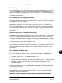
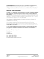
5.3 Additional features of the TC120
5.3.1 Setting the over-temperature thermostat
An over-temperature cut-out dial with a temperature scale is located at the top right of the
unit. The over-temperature probe independently monitors the bath temperature and
switches the heater off if it goes above the cut-out threshold. The T100 temperature cut-
out threshold is fixed at 110 °C. For the TC120, the temperature cut-out threshold can
be adjusted for convenience.
Coarse setting of the over-temperature thermostat
Rotate the temperature cut-out dial in line with the marked scale to the desired setting.
This should be higher than the set temperature to avoid operating the cut-out before the
set temperature has been reached.
If the alarm is triggered, it can be cancelled by pressing either the F or S button once.
The unit must then be switched off to clear the cut-out alarm. To continue to use the
TC120, let the bath liquid cool by at least 5°C either naturally or by replacing the liquid,
switch the unit off, wait 10 seconds and switch it on again to clear the alarm. To avoid
nuisance tripping the trip point needs to be set at least 5°C above the desired control
temperature.
Alternative setting of the over-temperature thermostat
Rotate the temperature cut-out dial to maximum (or at least a value above the level
required) and configure the set temperature to the cut-out level required. Leave the bath
to reach the set temperature and stabilise for at least 5 minutes. Turn the cut-out dial
slowly anticlockwise until the alarm lamp comes on and the alarm sounds intermittently.
The display will alternate between showing “Cut” and the liquid temperature. This gives
an over-temperature trip point at the set temperature. The audible alarm can be
cancelled by pressing either the F or S button once.
The unit must be switched off to clear the cut-out alarm. To continue to use the TC120,
let the bath liquid cool by at least 5°C either naturally or by replacing the liquid. To avoid
nuisance tripping the trip point needs to be set at least 5°C above the desired control
temperature.
5.3.2 Setting a countdown timer
The TC120 includes a countdown timer in minutes which triggers an audible alarm on
completion. The timer can be set between 1 minute and 6000 minutes (100 hours).
1. Press the F button twice – the display will show “Cloc”.
2. Press the S button to select.
3. Use the main dial to select “On” and press the S button to select. The display flashes
with time (in minutes) indicated. Rotate navigator control to set time required.
4. Press the S button to save and return to liquid temperature display with timer
countdown started.
When the countdown clock is set the display alternates between bath temperature and
time remaining in minutes.
When the countdown timer reaches zero the audible alarm will sound and the display will
alternate between the water temperature and “End”. The alarm can be accepted by
pressing the either the F or S buttons.
Note: the TC120 will continue to control at the set temperature after the timer
reaches zero – the heater will not switch off.

30423 V4 T100 & TC120
Page 17 Operating Manual
www.grantinstruments.com
5.3.3 Cancelling the timer
The countdown timer can be easily cancelled.
1. Press the F button twice – the display will show “Cloc”.
2. Press the S button to select.
3. Use the main dial to select “Off” and press the S button to select. The display will
revert to the bath temperature and the timer will be cancelled.
5.3.4 Setting a high temperature warning alarm
The high temperature alarm sets a warning buzzer to sound if the bath temperature
exceeds a defined level.
1. Press the F button three times – the display will show ”Alar”.
2. Press the S button to select.
3. Use the main dial to select “On” and press the S button to select. The display flashes
the high temperature alarm value. Rotate the dial to set the high temperature alarm
required.
4. Press the S button to save and return to liquid temperature.
If the high temperature alarm value is exceeded then TC120 will sound the buzzer
intermittently and show “-Al-” on the display. The alarm can be acknowledged by
pressing either the F or S buttons. However, the alarm is persistent and will trigger again
if the temperature still exceeds the high temperature value. The alarm can be cancelled
by following the steps above but using the dial to select “Off” in step 3 and pressing the S
button to confirm.
Note: the high temperature alarm will not switch off the heater.
5.3.5 Selecting liquid type
The liquid type determines the limits of the set temperature range.
1. Press the F button four times – the display will show the current liquid type.
2. Use the main dial to select the required liquid.
3. Press the S button to set the liquid type and return to normal temperature display.
Selection of the liquid types below changes the settable range as follows:
Liquid
Set temperature range
H2O
0°C to 100°C
Oil
0°C to 120°C
LTL*
-25° to 50°C
* LTL = low temperature liquid, for example 50% water/50% glycol

T100 & TC120 30423 V4
Operating Manual Page 18
www.grantinstruments.com
EN
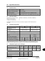
6.0 Technical specifications
6.1 Operating conditions
Ambient temperature range
5 to 40°C
Altitude above sea level
Up to 2,000m (6,500ft)
Operating environment
Indoor use only
Maximum relative humidity
80% RH up to 31°C decreasing to 50% RH at 40°C
6.2 Electrical details
Mains supply: 220-240V @ 50/60Hz or 110-120V @ 50/60Hz
Pollution degree: 2
Installation category: II
Mains supply voltage fluctuations are not to exceed ±10% of the nominal supply voltage.
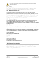
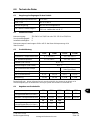
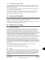
6.3 Product performance
T100
T100L
TC120
TC120L
Settable temperature range
0°C to 100°C
-25°C to 120°C
Min operating temperature
5°C to 100°C
-25°C to 120°C
Stability (DIN 12876)
±0.05°C *
Uniformity (DIN 12876)
±0.1°C
Max pump head pressure
-
210mBar (no flow)
Max pump flow rate
-
16l/min
Max current consumption
6.5A
12.5A
6.5A
12.5A
Heater power
1.3kW
1.4kW
1.3kW
1.4kW
* Temperature stability may be affected (±0.3C) in the presence of strong RF fields (10V/m) at
380-400MHz. This level of interference is very unlikely and is only likely to be encountered in
electrically noisy industrial locations as defined in EN61326)
6.4 Bath accessories information
ST5
ST12
ST18
ST26
ST38
Tank capacity (litres)
5
12
18
26
38
Liquid depth min/max (mm)
85/140
85/140
75/130
125/180
125/180
P5
P12
P18
Tank capacity (litres)
5
12
18
Liquid depth min/max (mm)*
85/140
85/140
85/140

30423 V4 T100 & TC120
Page 19 Operating Manual
www.grantinstruments.com
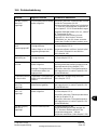
7.0 Technical Tips
7.1 Which water should you use in your bath?
For the long-term reliability of water baths it is important to use oxygenated water that is
free from ions and minerals that can cause corrosion of stainless steel. We recommend
the use of distilled water and de-ionised water from modern ion exchange systems that
do not use salt back flushing to regenerate the ion-exchange cartridges.
Stainless steel is protected from corrosion by a layer of chromium oxide. If the layer is
damaged, oxygen present in water can reform the oxide layer. If the water is still or de-
oxygenated, and the oxide layer is damaged, ions can corrode the stainless steel tank. If
a water bath has been unused for some time, or water boiled, we recommend changing
to fresh distilled water or correct de-ionised water.
Water normally contains calcium or magnesium ions. De-ionised water has most ions
removed as indicated by its conductivity level; the purer the water the lower the
conductivity. It is important to use only de-ionised water from an ion exchange system
with replaceable cartridges. Do not use de-ionised water generated from an ion-
exchange system that incorporates a salt back-flush system to regenerate the ion-
exchange resin as this can leave sodium ions that are very corrosive to stainless steel.
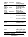
7.2 How to prevent rust in water baths
Most Grant tanks, as well as immersed parts, are made from type 304 stainless steel, an
extremely versatile general purpose grade of stainless steel. It is the excellent forming
characteristic that has made this grade dominant in the manufacture of laboratory and
industrial water baths, as well as domestic sinks and saucepans. Type 304 stainless
steel is highly suitable for applications where hygiene is important; it exhibits good heat
resistance and excellent resistance to corrosion.
However, despite resistance to general surface corrosion, stainless steel is susceptible to
specific types of corrosion, in particular pitting (small pin hole style corrosion) and stress
corrosion cracking. It can also undergo general corrosion in specific environments, such
as one containing hydrochloric or sulphuric acids.
Stainless steel is protected by its high content of alloying elements, primarily chromium
and nickel. Chromium is the most important with respect to corrosion resistance,
although the nickel assists in allowing the chromium to do its job. The chromium forms an
oxide layer on the surface of the steel, which inhibits further oxidation. This layer adheres
extremely well to the metal substrate, but it is essential that it remains intact, and must be
protected from various forms of damage.
If the surface chromium oxide layer becomes damaged, oxygen present in water can
partially reform the oxide layer, so it is advisable to ensure that water is always fresh and
well oxygenated. Baths that will be out of use for an extended period should be emptied,
and all moisture should be wiped from the bottom of the tank.
In some cases a brown layer may appear on the surface of a stainless steel tank. In most
of these cases this is not rust, but it may be a surface deposit of minerals from the local
water supply, or ferrous particles or salts that have fallen into the tank. These surface
deposits can usually be removed by using a household cleaner such as Duraglit or Silvo
metal polish.
Seite wird geladen ...
Seite wird geladen ...
Seite wird geladen ...
Seite wird geladen ...
Seite wird geladen ...
Seite wird geladen ...
Seite wird geladen ...
Seite wird geladen ...
Seite wird geladen ...
Seite wird geladen ...
Seite wird geladen ...
Seite wird geladen ...
Seite wird geladen ...
Seite wird geladen ...
Seite wird geladen ...
Seite wird geladen ...
Seite wird geladen ...
Seite wird geladen ...
Seite wird geladen ...
Seite wird geladen ...
Seite wird geladen ...
Seite wird geladen ...
Seite wird geladen ...
Seite wird geladen ...
Seite wird geladen ...
Seite wird geladen ...
Seite wird geladen ...
Seite wird geladen ...
Seite wird geladen ...
Seite wird geladen ...
Seite wird geladen ...
Seite wird geladen ...
Seite wird geladen ...
Seite wird geladen ...
Seite wird geladen ...
Seite wird geladen ...
Seite wird geladen ...
Seite wird geladen ...
Seite wird geladen ...
Seite wird geladen ...
Seite wird geladen ...
Seite wird geladen ...
Seite wird geladen ...
Seite wird geladen ...
Seite wird geladen ...
Seite wird geladen ...
Seite wird geladen ...
Seite wird geladen ...
Seite wird geladen ...
Seite wird geladen ...
Seite wird geladen ...
Seite wird geladen ...
Seite wird geladen ...
Seite wird geladen ...
Seite wird geladen ...
Seite wird geladen ...
Seite wird geladen ...
Seite wird geladen ...
Seite wird geladen ...
Seite wird geladen ...
Seite wird geladen ...
Seite wird geladen ...
Seite wird geladen ...
Seite wird geladen ...
Seite wird geladen ...
Seite wird geladen ...
Seite wird geladen ...
Seite wird geladen ...
Seite wird geladen ...
Seite wird geladen ...
Seite wird geladen ...
Seite wird geladen ...
Seite wird geladen ...
Seite wird geladen ...
Seite wird geladen ...
Seite wird geladen ...
Seite wird geladen ...
Seite wird geladen ...
Seite wird geladen ...
Seite wird geladen ...
Seite wird geladen ...
Seite wird geladen ...
Seite wird geladen ...
Seite wird geladen ...
Seite wird geladen ...
Seite wird geladen ...
Seite wird geladen ...
Seite wird geladen ...
Seite wird geladen ...
Seite wird geladen ...
Seite wird geladen ...
Seite wird geladen ...
Seite wird geladen ...
Seite wird geladen ...
Seite wird geladen ...
Seite wird geladen ...
Seite wird geladen ...
Seite wird geladen ...
Seite wird geladen ...
Seite wird geladen ...
Seite wird geladen ...
Seite wird geladen ...
Seite wird geladen ...
Seite wird geladen ...
-
 1
1
-
 2
2
-
 3
3
-
 4
4
-
 5
5
-
 6
6
-
 7
7
-
 8
8
-
 9
9
-
 10
10
-
 11
11
-
 12
12
-
 13
13
-
 14
14
-
 15
15
-
 16
16
-
 17
17
-
 18
18
-
 19
19
-
 20
20
-
 21
21
-
 22
22
-
 23
23
-
 24
24
-
 25
25
-
 26
26
-
 27
27
-
 28
28
-
 29
29
-
 30
30
-
 31
31
-
 32
32
-
 33
33
-
 34
34
-
 35
35
-
 36
36
-
 37
37
-
 38
38
-
 39
39
-
 40
40
-
 41
41
-
 42
42
-
 43
43
-
 44
44
-
 45
45
-
 46
46
-
 47
47
-
 48
48
-
 49
49
-
 50
50
-
 51
51
-
 52
52
-
 53
53
-
 54
54
-
 55
55
-
 56
56
-
 57
57
-
 58
58
-
 59
59
-
 60
60
-
 61
61
-
 62
62
-
 63
63
-
 64
64
-
 65
65
-
 66
66
-
 67
67
-
 68
68
-
 69
69
-
 70
70
-
 71
71
-
 72
72
-
 73
73
-
 74
74
-
 75
75
-
 76
76
-
 77
77
-
 78
78
-
 79
79
-
 80
80
-
 81
81
-
 82
82
-
 83
83
-
 84
84
-
 85
85
-
 86
86
-
 87
87
-
 88
88
-
 89
89
-
 90
90
-
 91
91
-
 92
92
-
 93
93
-
 94
94
-
 95
95
-
 96
96
-
 97
97
-
 98
98
-
 99
99
-
 100
100
-
 101
101
-
 102
102
-
 103
103
-
 104
104
-
 105
105
-
 106
106
-
 107
107
-
 108
108
-
 109
109
-
 110
110
-
 111
111
-
 112
112
-
 113
113
-
 114
114
-
 115
115
-
 116
116
-
 117
117
-
 118
118
-
 119
119
-
 120
120
-
 121
121
-
 122
122
-
 123
123
-
 124
124


Grant Instruments Optima TC120 Bedienungsanleitung
- Typ
- Bedienungsanleitung
- Dieses Handbuch eignet sich auch für
in anderen Sprachen
Verwandte Artikel
Andere Dokumente
-
 Lauda Ecoline Bedienungsanleitung
-
Techne TE-10D Benutzerhandbuch
-
Thrustmaster 4069006 4060051 4068007 Benutzerhandbuch
-
Sony STR-DH700 Installationsanleitung
-
Videotec MAXIMUS MPX SERIES2 Benutzerhandbuch
-
WIKA IntelliTHERM TGT73 Bedienungsanleitung
-
-
Raychem T-M-20-S/+X+Y/EX Benutzerhandbuch
-
Mettler Toledo 30 425 550 Benutzerhandbuch
