
443 405 --002 990212 Valid from Machine no 452 XXX--XXXX
A6 PAK
Control system for motorised slides
Steuersystem für motorisierte Schlitten
Système de command e pour les glissières
motorisées
Bedieningssysteem voor schuiven met
motoraandrijving
Operating manual
Bedienungsanleitung
Manuel de l’opérateur
Gebruikershandboek

TECHNICAL DESCRIPTION 2.............................
INSTALLATION 7........................................
OPERATION 8..........................................
MAINTENANCE 8....................................
TECHNISCHE BESCHREIBUNG 10.........................
INSTALLATION 15........................................
BETRIEB 16..............................................
WARTUNG 16.........................................
DESCRIPTION TECHNIQUE 18............................
INSTALLATION 23........................................
FONCTIONNEMENT 24...................................
ENTRETIEN 24........................................
TECHNISCHE BESCHRIJVING 26..........................
INSTALLATIE 31..........................................
GEBRUIK 32.............................................
ONDERHOUD 32......................................
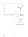
DIMENSION DRAWING - MASSBILD - COTES
D’ENCOMBREMENT - MAATSCHE TS 33..............
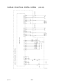
DIAGRAM - SCHALTPLAN - SCHÉMA - SCHEMA (418 138) 34
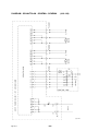
DIAGRAM - SCHALTPLAN - SCHÉMA - SCHEMA (418 139) 35
Rights reserved to alter specifications without notice.
Änderungen vorbehalten.
Sous réserve de modifications sans avis préalable.
Recht op wijzigingen zonder voorafgaande medeleling voorbehouden.

-- 1 --
mmvarnea
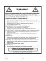
WARNING
ARC WELDING AND CUTTING CAN BE INJURIOUS TO YOURSELF AND
OTHERS. TAKE PRECAUTIONS WHEN WELDING. ASK FOR YOUR
EMPLOYER’S SAFETY PRACTICES WHICH SHOULD BE BASED ON MANU--
FACTURER’S HAZARD DATA.
ELECTRIC SHOCK -- Can kill
S Install and earth the welding unit in accordance with applicable standards.
S Do not touch live electrical parts or electrodes with bare skin, wet gloves or
wet clothing.
S Insulate yourself from earth and the workpiece.
S Ensure your working stance is safe.
FUMES AND GASES -- Can be dangerous to health
S Keep your head out of the fumes.
S Use ventilation, extraction at the arc, or both, to keep fumes and gases from
your breathing zone and the general area.
ARC RAYS -- Can inju re eyes and burn skin
S Protect your eyes and body. Use the correct welding screen and filter lens
and wear protective clothing.
S Protect bystanders with suitable screens or curtains.
FIRE HAZARD
S Sparks (spatter) can cause fire. Make sure therefore that there are no
inflammable materials nearby.
NOISE -- Excessive noise can da mage hearing
S Protect your ears. Use ear defenders or other hearing protection.
S Warn bystanders of the risk.
MALFUNCTION
S Call for expert assistance in the event of malfunction.
READ AND UNDERSTAND THE OPERATING MANUAL
BEFORE INSTALLING OR OPERATING.
PROTECT YOURSELF AND OTHERS!

TECHNICAL DESCRIPTION
-- 2 --
dgb1d1ea
TECHNICAL DESCRIPTION
A6 PAK is a control system for motorised slides.
The system is available in two versions:
1. as a complete standard system with or without remote control unit for automatic
welding machines
S Joint tracking unit, order no. 417 587--880
S Joint tracking unit with remote control, order no. 417 587--882
2. as a build--in component for a column and boom
S Joint tracking unit, order no. 417 587--881
agb1d003

TECHNICAL DESCRIPTION
-- 3 --
dgb1d1ea
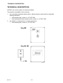
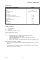
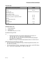
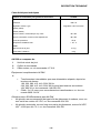
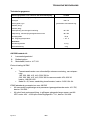
Technical data
Control system for motorised slides A6 PAK
Supply and control voltage 42V AC 50--60 Hz
Power 460 V A
Motor regulator , model Switched four quadrant reg.
Speed (high)
Speed (low)
Rotor voltage, Joy--stick control 40 V DC
Stator voltage, independent magnet motor 48 V DC
Enclosure class IP 53
Max. ambient temperature +45_ C
Weight:
Joint tracking unit 4.5 kg
Remote control 2kg
A6 PAK consists of:
1 Joint tracking unit
2 Control unit
3 Motor cable, order no. 417 310.
Optional equipment for A6 PAK
4
S Transformer to provide separate power supply from mains
190, 220, 380, 415, 440, 500V 50 Hz
200, 230, 380, 415, 440, 500V 60 Hz to secondary 42V, 660 VA
order no. 148 636--002
S Cable 3 x 2.5 mm
2
, for connection to transformer, order no. 2626 134--04.
ESAB standard servo slides for A6 PAK
S A6 servo slide, ball screw type with permanent magnet motor 42 V DC, order no.
334 333.
S A6 motor--driven slide, sliding on runners, with A6 VEC motor 42V -- 4000 rpm,
gear ratio 74:1, order no. 334 426.

TECHNICAL DESCRIPTION
-- 4 --
dgb1d1ea
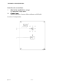
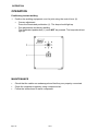
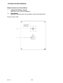
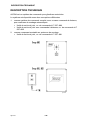
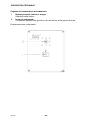
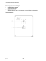
Controls and connections
1 Illuminated pushbutton, orange
For selection of high speed
2 Control lever
Manual operation of servo slides up/down and left/right
Location of components:
agb1d002

TECHNICAL DESCRIPTION
-- 5 --
dgb1d1ea
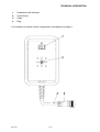
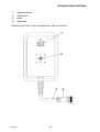
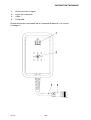
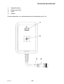
1 Pushbutton with indicator
2 Control lever
3 Cable
4 Plug
For locations of remote control components, see diagram on page 5.
dgb1s003

TECHNICAL DESCRIPTION
-- 6 --
dgb1d1ea
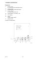
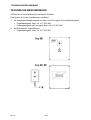
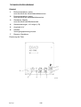
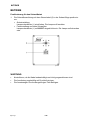
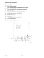
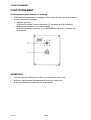
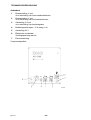
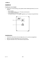
Rear panel
1 Socket, 4 pin.
for connecting horizontal slide motor
2 Socket, 4 pin.
for connecting vertical slide motor
3 Socket, 23 pin.
for connecting control unit
4 Control fuses, 10 A slow (1 off)
5 42 V supply
6 Switch
Supply voltage on/off
7 Spare socket
Location of components:
agb1d005

INSTALLATION
-- 7 --
dgb1i1ea
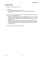
INSTALLATION
1. For dimensions, see dimensional drawing on page 33.
2. Connection
S see drawing for welding machine on page 34.
S see drawing for column and boom, welding machine and remote control unit
on page 35.
3. Make sure the required power and voltage supplies are available for the entire
installation.
S If any of the power sources LAE 800 -- 1000 -- 1250 -- 1600 are used, and is
set up to supply a control voltage of 42 V, then the required voltage can be
taken from the standard welding machine, see PEG1 socket.
S If the required voltage is not available, or if a LAH 500 --630 42 V power
source is used, then a special power supply must be provided using the 42 V
transformer for A6 PAK (see optional equipment).
4. Controls, see diagram on page 4.

OPERATION
-- 8 --
dgb1o1ea
OPERATION
Positioning to start welding
1. Position the welding equipment over the joint using the control lever (2).
S Coarse adjustment
Press the illuminated pushbutton (1). The lam p should light up.
S Fine adjustment and during welding
The illuminated pushbutton ( 1) must NOT be pressed. The lamp should not
light up.
agb1d0x2
MAINTENANCE
S Check that the cables are undamaged and that they are properly connected.
S Clean the equipment regularly using compressed air.
S Follow the instructions for each component.

-- 9 --
mmvarnga
WARNUNG
BEIM LICHTBOGENSCHWEIßEN UND LICHTBOGENSCHNEIDEN KANN IHNEN
UND ANDEREN SCHADEN ZUGEFÜGT WERDEN. DESHALB MÜSSEN SIE BEI
DIESEN ARBEITEN BESONDERS VORSICHTIG SEIN. BEFOLGEN SIE DIE
SICHERHEITSVORSCHRIFTEN IHRES ARBEITGEBERS, DIE SICH AUF DEN
WARNUNGSTEXT DES HERSTELLERS BEZIEHEN.
ELEKTRISCHER SCHLAG -- Kann den Tod bringen.
S Die Schweißausrüstung gemäß örtlichen Standards installieren und erden.
S Keine Stromführenden Teile oder Elektroden mit bloßen Händen oder mit nasser
Schutzausrüstung berühren.
S Personen müssen sich selbst von Erde und Werkstück isolieren.
S Der Arbeitsplatz muß sicher sein.
RAUCH UND GAS -- Können Ihre Gesundheit gefährden.
S Das Angesicht ist vom Schweißrauch wegzudrehen.
S Ventilieren Sie und saugen Sie den Rauch aus dem Arbeitsbereich ab.
UV-- UND IR--LICHT -- Können Brandschäden an Augen und Haut verursachen
S Augen und Körper schützen. Geeigneten Schutzhelm mit Filtereinsatz und
Schutzkleider tragen.
S Übriges Personal in der Nähe, ist durch Schutzwände oder Vorhänge zu
schützen.
FEUERGEFAHR
S Schweißfunken können ein F euer entzünden. Daher ist dafür zu sorgen, daß
sich am Schweißarbeitsplatz keine brennbaren Gegenstände befinden.
GERÄUSCHE -- Übermäßige Geräusche kö nn en Gehö rschäden verursachen
S Schützen Sie ihre Ohren. Benutzen Sie Kapselgehörschützer oder andere
Gehörschützer.
S Warnen Sie Umstehende vor der Gefahr.
BEI STÖRUNGEN
S Nur Fachleute mit der Behebung von Störungen beauftragen.
LESEN SIE DIE BETRIEBSANWEISUNG VOR DER
INSTALLATION UND INBETRIEBNAHME DURCH.
SCHÜTZEN SIE SICH SELBST UND ANDERE!

TECHNISCHE BESCHREIBUNG
-- 1 0 --
dgb1d1ga
TECHNISCHE BESCHREIBUNG
A6 PAK ist ein Steuersystem für motorisierte Schlitten.
Das System ist in zwei Ausführungen erhältlich:
1. Als komplettes Standardsystem mit oder ohne Fernregler für Schweißautomaten
S Fugenabtastgerät, Best.--Nr. 417 587-- 880
S Fugenabtastgerät mit Fernregler, Best.--Nr. 417 587 --882
2. als Einbauteil für Schweißkrane
S Fugenabtastgerät, Best.--Nr. 417 587-- 881
agb1d003

TECHNISCHE BESCHREIBUNG
-- 1 1 --
dgb1d1ga
Tekniska data
Steuersystem für motorisierte Schlitten A6 PAK
Anschluß-- und Steuerspannung 42V AC 50--60 Hz
Leistung 460 V A
Motorregler, Typ Geschalteter Vierquadrantregler
Geschwindigkeit (hoch)
Geschwindigkeit (niedrig)
Ankerspannung, Joy--Stick--Steuerung 40 V DC
Feldspannung, separater magnetisierter Motor 48 V DC
Schutzart IP 53
Max. Umgebungstemperatur +45_ C
Gewichte:
Fugenabtastgerät 4.5 kg
Fernregler 2kg
A6 PAK besteht aus :
1 Fugenabtastgerät
2 Bedieneinheit
3 Motorkabel, Best. --Nr. 417 310.
Zusatzausrüstung A6 PAK
4
S Zwischentransformator für getrennte Spannungsversorgung, von
190, 220, 380, 415, 440, 500V 50 Hz Netzspannung
200, 230, 380, 415, 440, 500V 60 Hz auf 42V, 660 VA Sekundärspan-
nung. Best.--Nr. 148 636--002
S Kabel 3 x 2,5 mm
2
, für Transformatoranschluß, Best.--Nr. 2626 134--04.
ESAB Standard--Servoschlitten für A6 PAK
S A6--Servoschlitten aus Kugelbuchsentyp mit dauermagnetisiertem Motor 42 V
DC, Best.--Nr. 334 333.
S A6 motorgetriebener Schlitten, gleitgelagerter langer Läufer, mit A6 VEC--Motor
42V -- 4000 U/min, Übersetzung 74:1, Best.--Nr. 334 426.

TECHNISCHE BESCHREIBUNG
-- 1 2 --
dgb1d1ga
Bedienelemente und Anschlü sse
1 Lampendrucktaste, orange
Wahl einer hohen Geschwindigkeit
2 Steuerhebel
Manuelle Steuerung der Servoschlitten auf/ab und links/rechts
Plazierung der Teile:
agb1d002

TECHNISCHE BESCHREIBUNG
-- 1 3 --
dgb1d1ga
1 Signaldrucktaste
2 Steuerhebel
3 Kabel
4 Stiftstecker
Plazierung der Teile für den Fernregler siehe Abb. auf Seite 13.
dgb1s003

TECHNISCHE BESCHREIBUNG
-- 1 4 --
dgb1d1ga
Rückteil
1 Buchsensteckdose, 4polig
zum Anschluß des Horizontalschlittenmotors
2 Buchsensteckdose, 4polig
zum Anschluß des Vertikalschlittenmotors
3 Steckdose, 23polig
zum Anschluß einer Bedieneinheit
4 Steuersicherungen, 10 A träge (1 St)
5 Anschluß 42 V
6 Schalter
Versorgungsspannung ein/aus
7 Reserve--Steckdose
Plazierung der Teile:
agb1d005

INSTALLATION
-- 1 5 --
dgb1i1ga
INSTALLATION
1. Maßangaben, siehe Maßbilder auf Seite 33.
2. Anschluß
S siehe Schaltplan für Automatikausführung auf Seite 34.
S siehe Schaltplan für Kranausführung und Automatikausführung mit Fern-
regler auf Seite 35.
3. Kontrollieren, ob die erforder liche Leistung und Spannung für eine komplette In-
stallation zugänglich ist.
S Wenn eine Stromquelle vom Typ LAE 800 -- 1000 -- 1250 -- 1600 verwendet
und an eine Steuerspannung von 42 V angeschlossen wird, kann die not-
wendige Leistung vom Standardautomaten erhalten werden, siehe Anschluß
PEG1.
S Wenn keine geeignete Spannung vorhanden ist oder die Stromquelle
LAH 500 --630 42 V angewendet wird, ist immer eine besondere Stromversor-
gung mit dem Zwischentransfor m ator 42 V für A6 PAK zu installieren (siehe
Zubehör).
4. Bedienelemente siehe Abb. auf Seite 12.

BETRIEB
-- 1 6 --
dgb1o1ga
BETRIEB
Positionierung für den Schweißstart
1. Die Schweißausrüstung mit dem Steuerhebel (2) in der Schweißfuge positionie-
ren.
S Grobeinstellung
Lampendrucktaste (1) eindrücken. Die Lampe soll leuchten.
S Feineinstellung und beim Schweißen.
Lampendrucktaste (1) soll NICHT eingedrückt sein. Die Lampe soll erloschen
sein.
agb1d0x2
WARTUNG
S Kontrollieren, ob die Kabel unbeschädigt und richtig angeschlossen sind.
S Die Ausrüstung regelmäßig mit Druckluft reinigen.
S Die Anweisungen für die dazugehörigen Teile befolgen.

-- 1 7 --
mmvarnfa
AVERTISSEMENT
LE SOUDAGE ET LE COUPAGE À L’ARC PEUVENT ÊTRE DANGEREUX POUR
VOUS COMME POUR AUTRUI. SOYEZ DONC TRÈS PRUDENT EN UTILISANT
LA MACHINE À SOUDER. OBSERVEZ LES RÈGLES DE SÉCURITÉ DE VOTRE
EMPLOYEUR, QUI DOIVENT ÊTRE BASÉES SUR LES TEXTES D’AVERTISSE-
MENT DU FABRICANT
DÉCHARGE ÉLECTRIQUE -- Peut être mortelle
S Installer et mettre à la terre l’équipement de soudage en suivant les
normes en vigueur.
S Ne pas toucher les parties conductrices. Ne pas toucher les électrodes avec
les mains nues ou des gants de protection humides.
S Isolez--vous du sol et de la pièce à travailler.
S Assurez--vous que votre position de travail est sûre.
FUMÉES ET GAZ -- Peuvent être nuisibles à votre santé
S Eloigner le visage des fumées de soudage.
S Ventiler et aspirer les fumées de soudage pour assurer un environnement de
travail sain.
RADIATIONS LUMINEUSES DE L’ARC -- Peuvent abîmer les yeux et causer des
brûlures à l’épiderme
S Se protéger les yeux et l’épiderme. Utiliser un écran soudeur et porter des
gants et des vêtements de protection.
S Protéger les personnes voisines des effets dangereux de l’arc par des rideaux
ou des écrans protecteurs.
RISQUES D’INCENDIE
S Les étincelles (ou ”puces” de soudage) peuvent causer un incendie. S’assurer
qu’aucun objet inflammable ne se trouve à proximité du lieu de soudage.
BRUIT -- Un niveau élevé de bruit p eut nu ire à vos facu lt és auditives
S Protégez--vous. Utilisez des protecteur s d’oreilles ou toute autre protection
auditive.
S Avertissez des risques encourrus les personnes se trouvant à proximité.
EN CAS DE MAUVAIS FONCTIONNEMENT
S Faire appel à un technicien qualifié.
LIRE ATTENTIVEMENT LE MODE D’EMPLOI AVANT
D’INSTALLER LA MACHINE ET DE L’UTILISER.
PROTÉGEZ--VOUS ET PROTÉGEZ LES AUTRES!

DESCRIPTION TECHNIQUE
-- 1 8 --
dgb1d1fa
DESCRIPTION TECHNIQUE
A6 PAK est un système de comm ande pour glissières motorisées.
Le système est disponible sous deux conceptions différentes:
1. comme système d e commande complet, avec ou sans commande à distance,
pour machines de soudage automatiques
S Unité de suivie de joint, no. de commande 417 587--880
S Unité de suivie de joint avec commande à distance, no. de commande 417
587--882
2. comme composant montable sur potences de soudage
S Unité de suivie de joint, no. de commande 417 587--881
agb1d003
Seite wird geladen ...
Seite wird geladen ...
Seite wird geladen ...
Seite wird geladen ...
Seite wird geladen ...
Seite wird geladen ...
Seite wird geladen ...
Seite wird geladen ...
Seite wird geladen ...
Seite wird geladen ...
Seite wird geladen ...
Seite wird geladen ...
Seite wird geladen ...
Seite wird geladen ...
Seite wird geladen ...
Seite wird geladen ...
Seite wird geladen ...
Seite wird geladen ...
-
 1
1
-
 2
2
-
 3
3
-
 4
4
-
 5
5
-
 6
6
-
 7
7
-
 8
8
-
 9
9
-
 10
10
-
 11
11
-
 12
12
-
 13
13
-
 14
14
-
 15
15
-
 16
16
-
 17
17
-
 18
18
-
 19
19
-
 20
20
-
 21
21
-
 22
22
-
 23
23
-
 24
24
-
 25
25
-
 26
26
-
 27
27
-
 28
28
-
 29
29
-
 30
30
-
 31
31
-
 32
32
-
 33
33
-
 34
34
-
 35
35
-
 36
36
-
 37
37
-
 38
38


in anderen Sprachen
- français: ESAB A6 PAK Manuel utilisateur
- Nederlands: ESAB A6 PAK Handleiding
Verwandte Artikel
-
ESAB PAV Benutzerhandbuch
-
-
-
-
-
-
-
-
-