Tripp Lite Extended-Run Battery Cabinet Bedienungsanleitung
- Kategorie
- Wiederaufladbare Batterien
- Typ
- Bedienungsanleitung

1
1111 W. 35th Street, Chicago, IL 60609 USA • www.tripplite.com/support
Copyright © 2018 Tripp Lite. All rights reserved.
Owner’s Manual
Extended-Run
Battery Cabinet
Models: BP480V40, BP480V40-NIB, BP480V65,
BP480V65-NIB, BP480V100, BP480V100-NIB
Not suitable for mobile applications.
Español 36 • Français 71 • Русский 106 • Deutsch 141
18-09-176-933861.indb 1 9/26/2018 10:54:10 AM

2
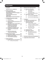
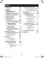
Table of Contents
1. Introduction 3
Features 3
2. Important Safety 4
Instructions
Installation and 4
Location Warnings
Connection Warnings 4
Battery Warnings 5
3. Battery Cabinet Installation 7
3.1 Preparation 7
3.2 Transportation 7
3.3 Mechanical Check 7
3.4 Internal Wiring (Typical) 8
3.5 Preliminary Electrical Check 8
(After Battery Installation)
3.6 Battery Cabinet Placement 8
3.7 Electrical Connection 9
3.8 Final Electrical Check 10
4. Operation and Charging 11
4.1 Determine Charging Voltages 11
4.2 Initial Charge 11
4.3 Operational Check 11
5. Maintenance 11
5.1 Maintenance Schedule 11
5.1.1 Quarterly Check 11
6. Mechanical Data 12
6.1 Physical Measurements 12
6.1.1 BP480V40/NIB 12
Measurements
6.1.2 BP480V65/NIB and 13
BP480V100/NIB
Measurements
6.2 Battery Requirements 14
6.2.1 BP480V40/NIB Battery 14
6.2.2 BP480V65/NIB Battery 14
6.1.3 BP480V100/NIB Battery 14
7. Installation 15
7.1 Battery Pre-Installation 15
7.2 Cable Jumpers and 16
Internal Wiring
7.2.1 Included Cable 16
Jumpers Specifications
7.2.2 Installing Cable Jumpers 17
to Battery Terminals
7.2.3 Battery Cabinet 18
Internal Wiring
7.3 Battery Installation 21
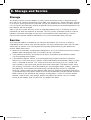
7.4 Installation Specifications 33
7.4.1 Installation and 33
Floor Loading Information
7.4.2 Recommended Torque 33
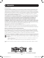
8. Storage and Service 34
9. Warranty 35
18-09-176-933861.indb 2 9/26/2018 10:54:10 AM

3
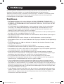
1. Introduction
Tripp Lite’s Extended-Run Battery Cabinets connect to SmartOnline® UPS Systems to provide
long-lasting battery backup for data centers, telecommunications, networks, industrial
facilities, security, emergency systems and other mission-critical applications that require high
capacity, high availability and extended runtime.
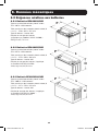
Features
• Battery cabinets are available in six options: BP480V40, BP480V40-NIB, BP480V65,
BP480V65-NIB, BP480V100 and BP480V100-NIB. The BP480V40, BP480V65 and
BP480V100 models include jumpers, terminals, breaker, and 40 x CSB GP 12400,
GP 12650 or GPL 121000 batteries in a separate pallet for a complete installation. The
BP480V40-NIB, BP480V65-NIB and BP480V100-NIB models are a similar kit but without
batteries, allowing users the flexibility to purchase batteries for the cabinet separately.
• Battery cabinets are available in voltages of 480V DC and capacities option of 40Ah, 65Ah
and 100Ah@C20 to 1.67VPC
• Battery cabinets contain multiple 12V DC batteries connected in series for higher voltages.
• Each battery cabinet contains 4 shelves with 10 individual batteries (maximum) per shelf.
• Hinged lockable door facilitates access to batteries for periodic maintenance.
• A minimum of 100 mm clearance is located above the individual batteries for access to
terminals.
• Battery cabinet is constructed of heavy-gauge steel.
• Baked powder-coat finish provides chip and corrosion resistance.
• Battery cabinet ships bolted to pallet with a double layer of protective stretch wrap and
integrated corner and top protection.
• Appropriate ventilation and convection cooling of individual batteries is provided via spacing
between batteries. Front and rear vents allow the free flow of warmer air out of the battery
cabinet.
• A molded case circuit breaker is provided for overcurrent protection.
• User-supplied power output cables can be fed into the battery cabinet via built-in conduit
knockouts on top of the cabinet.
• For improved safety, higher power density and minimized maintenance, the cabinet
systems use Valve-Regulated Lead-Acid (VRLA) recombinant batteries. The electrolyte in
these batteries is immobilized in either an absorbent mat separator or a gelling medium,
eliminating the spilling hazards and maintenance requirements of free liquid electrolyte.
There is no need to add water or measure specific gravity.
• Because the batteries are recombinant cells that employ an oxygen recombination cycle,
minimal gasses are emitted during normal float charging. Each cell contains an individual
valve, which releases the gas products from overcharge and prevents pressure build-up
within the cell.
18-09-176-933861.indb 3 9/26/2018 10:54:10 AM

4
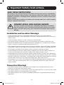
2. Important Safety Instructions
SAVE THESE INSTRUCTIONS
All sections of this manual contain instructions and warnings that must be followed
during the installation and operation of the battery cabinet described in this manual.
Read ALL instructions thoroughly before attempting to move, install or connect your
battery cabinet.
Failure to heed these warnings may affect your warranty and cause serious property
damage and/or personal injury.
DANGER! LETHAL HIGH-VOLTAGE HAZARD!
All wiring should be performed by a qualified electrician in accordance
with the warnings in this manual and all applicable electrical and safety
codes. Incorrect wiring may cause serious personal injury and property
damage.
Installation and Location Warnings
• Install the battery cabinet in a controlled indoor environment, away from moisture,
temperature extremes, flammable liquids and gasses, conductive contaminants, dust and
direct sunlight.
• Install the battery cabinet in a level, structurally sound location.
• The battery cabinet is extremely heavy. Exercise caution when moving or lifting the unit.
• Operate the battery cabinet at indoor temperatures between 0° C and 40° C only. For best
results, maintain an ambient indoor temperature of 25° C.
• Allow adequate space around the front and rear of the battery cabinet for proper ventilation.
Do not block, cover or insert objects into the battery cabinet’s external ventilation openings.
• Do not place any object on the battery cabinet, especially containers of liquid.
• Do not attempt to stack the battery cabinet. Attempting to stack the battery cabinet may
cause permanent damage and create a potential for serious personal injury.
• Do not attempt to unpack or move the battery cabinet without assistance. Use appropriate
handling equipment rated to bear the weight and bulk of the battery cabinet, such as freight
elevators, pallet jacks and forklifts. (Fully extend forks under load. Spread forks to maximum
possible width under load. Lift cabinet from bottom only. Wear safety shoes.)
• For emergency use, install a fire extinguisher rated for energized electrical equipment fires
(Class C rating or exact equivalent, with a non-conductive extinguishing agent) near the
battery cabinet.
Connection Warnings
• The battery cabinet contains hazardous high voltages that have the potential to cause
personal injury or death from electric shock.
• The battery cabinet has its own energy source. The output terminals may be live, even when
the battery cabinet is not connected to a UPS system.
• The battery cabinet must be suitably grounded according to all applicable electrical wiring
regulations.
18-09-176-933861.indb 4 9/26/2018 10:54:10 AM

5
2. Important Safety Instructions
• Use of this equipment in life support applications where failure of this equipment can
reasonably be expected to cause the failure of the life support equipment or to significantly
affect its safety or effectiveness is not recommended.
• De-energize all input and output power sources before installing cables or making electrical
connections.
• Use flexible cable of sufficient length to permit battery cabinet servicing.
• Use ferrule caps to cover termination cables and prevent frayed ends from shorting on
terminal blocks. Use cabling rated VW-1, FT-1 or better. Use cable sleeves and connector
clamps.
• Confirm all cables are marked correctly according to their purpose, polarity and diameter.
• Observe proper polarity by following the positive and negative markings on the unit. Failure
to observe proper polarity may damage the batteries and create a serious risk of personal
injury and property damage.
• Wiring and assembly should be performed by trained, qualified electricians only. Refer to the
UPS unit’s Owner’s Manual for wire sizing.
Battery Warnings
• The battery cabinet does not require routine maintenance by the user. There are no user-
serviceable parts inside. Only qualified, knowledgeable service personnel familiar with all
required precautions should open the access panels for any reason. Keep unauthorized
personnel away from batteries.
• The battery cabinet contains valve-regulated recombinant lead-acid (VRLA) batteries. Do not
attempt to add water to these batteries or sample the electrolyte specific gravity.
• VRLA batteries can contain an explosive mixture of hydrogen gas. DO NOT SMOKE when
near batteries. DO NOT cause flames or sparks near batteries. Discharge static electricity
from body before touching batteries. DO NOT open or mutilate batteries—released
electrolyte is harmful to the skin and eyes and may be toxic. DO NOT dispose of batteries in
a fire—they may explode.
• Batteries present a risk of electrical shock and burns from high short-circuit current.
Battery connection or replacement should be performed only by qualified service personnel
observing proper precautions. Use tools with insulated handles. Remove watches, rings
or other metal objects. Wear rubber gloves and boots. Do not short or bridge the battery
terminals with any object. Do not lay tools or metal parts on top of batteries.
• Replace batteries with equivalent batteries (same number and type) available from
Tripp Lite.
• The batteries are recyclable. Refer to local codes for disposal requirements. Do not dispose
of batteries except through approved channels in accordance with all applicable local, state
and national regulations.
• Do not connect or disconnect batteries when the UPS system is operating from the battery
supply or when the unit is not in bypass mode. Disconnect the charging source prior to
connection or disconnecting battery terminals.
• If the charging source remains off for an extended period of time, it should be turned on
periodically to allow the batteries to recharge. The charging source should be turned on
and the batteries should be recharged at least one uninterrupted 24-hour period every
3 months. Failure to recharge the batteries periodically may cause permanent battery
damage.
18-09-176-933861.indb 5 9/26/2018 10:54:11 AM

6
2. Important Safety Instructions
• Allow batteries to charge uninterrupted for 24 hours after installation.
• Do not attempt to service the integrated battery charger (included with “C” models
only). Contact Tripp Lite if service is required.
Note on Labeling
These symbols may appear on the product label:
V~: AC Voltage
V : DC Voltage
: Ground
+: Battery Positive
–: Battery Negative
Refer to the product label for model numbers, voltage ratings and other
important information.
18-09-176-933861.indb 6 9/26/2018 10:54:11 AM

7
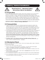
3. Battery Cabinet Installation
Read Section 2 – Important Safety
Instructions Before Installation
3.1 Preparation
• At your site, prepare to off-load the battery cabinet from the delivery truck and transport it
to the final installation location. Consider both the packaged weight and dimensions.
• Make sure the floor can support the load of the specific battery cabinet being installed. The
battery cabinet must be installed in a structurally sound area with a level floor that is able to
bear the weight of the battery cabinet and other equipment that will be installed nearby.
• Draw a wiring schematic representing the cables connected between the battery cabinet’s
output terminal blocks and any external disconnect device, junction box and/or load/rectifier.
• If you plan to store the battery cabinet for an extended period before or after installation,
follow the instructions in Section 8. Storage and Service.
3.2 Transportation
1. Inspect the shipping container(s) for visible damage (do not remove the stretch wrap
around the unit until it has been transported to the final installation location). Confirm
that the model name and rating match the unit you ordered. If you determine the unit has
been damaged during shipping or if anything appears to be missing, contact Tripp Lite for
assistance. Do not attempt to use the unit if it has been damaged or mishandled.
2. Do not attempt to move or unpack the battery cabinet without assistance. Use appropriate
handling equipment rated to bear the weight and bulk of the battery cabinet, such as
freight elevators, pallet jacks and forklifts. (Fully extend forks under load. Spread forks to
maximum possible width under load. Lift cabinet from bottom only. Wear safety shoes.)
Confirm load limits for freight elevators, handling equipment and floors along the transport
route are not exceeded by the combined weight of the packaged battery cabinet, handling
equipment and personnel. Confirm that the packaged unit will pass through any doorways
along the intended route.
3. The battery cabinet is secured with stretch wrap to protect it during shipping and
movement within a facility. Remove the stretch wrap from the battery cabinet when the
unit is in the final installation location—not before.
3.3 Mechanical Check
While the assembled cabinet battery system is still on the shipping pallet, inspect all sides for
impact or other damage.
1. Open the front door of the battery cabinet.
2. Confirm none of the individual batteries included on a separate pallet are damaged
(applies to BP480V40, BP480V65 and BP480V100 models only).
3. Confirm none of the internal parts (terminal blocks, circuit breakers and other parts) have
been damaged.
4. Note the individual battery model number. Refer to Section 6.2 for the battery’s terminal
type and recommended torque.
5.
Use insulated tools to tighten all battery terminal connections to the recommended torque.
6. Use insulated tools to tighten the cables from the positive and negative output terminals
at the end batteries to the circuit breaker.
18-09-176-933861.indb 7 9/26/2018 10:54:11 AM

8
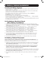
3.4 Internal Wiring (Typical)
• Battery cabinets use multiple 12V DC batteries connected in series to provide nominal DC
voltage of 480V DC (±240V DC).
• Internal cabling is sized for specific application load currents. Do not use any other cable
size other than the one provided in the battery cabinet.
• Each battery cabinet shelf includes a specific wiring diagram. Refer to Section 7.
Installation for battery installation details.
• All circuit breakers are in the middle tier of the battery cabinet.
• All load connection polarities will be labeled as “+” (battery positive), “-“ (battery negative)
and “N” (battery center tap) for ±240V DC strings.
• All battery cabinets are provided with a branch circuit overcurrent protection device and may
be wired directly to the load or UPS.
3.5 Preliminary Electrical Check
(After Battery Installation)
1. With the circuit breaker OFF, measure the battery voltage at the line side of the circuit
breaker using a digital voltmeter. Refer to the diagrams in Section 7.2.3 Battery Cabinet
Internal Wiring for more information.
2. Using a digital voltmeter, measure +240V between the “+” (battery positive) and “N”
(battery center tap). Confirm the voltage measures a minimum of +220V DC.
3. Using a digital voltmeter, measure -240V between the “-” (battery negative) and “N”
(battery center tap). Confirm the voltage measures a minimum of -220V DC.
4. Using a digital voltmeter, measure +480V between the “+” (battery positive) and the “-”
(battery negative). Confirm the voltage measures a minimum of +440V DC.
5. If the measured voltage is significantly different than anticipated, determine the cause
(e.g. low charge, shorted cell, reversed battery, faulty wiring) and correct the voltage
disparity before proceeding.
6. Set the circuit breaker to the “off” position as a safety precaution during installation.
3.6 Battery Cabinet Placement
Place the battery cabinet in a cool location with free airflow and away from direct heat
sources. The lifespan and performance of a battery may be dramatically affected by elevated
temperature, decreasing 50% for each 8.25° C above 25° C.
1. Prepare the surface where the cabinet will be placed. The surface must be clean, flat and
able to support the battery cabinet and other equipment installed nearby. See Section
7.4 for floor loading specifications.
2. Allow adequate clearance around the front and rear of the battery cabinet for ventilation
and maintenance. The front door must be accessible to allow easy access to internal
batteries, internal fuses and other overcurrent protection devices. See Section 6.1 for
dimensions and battery cabinet measurements.
3. If the cabinet will be anchored to the floor, install appropriate anchor bolts in the mounting
hole located at the bottom of the cabinet. Use washers to create a level surface between
the mounting areas around the anchor bolts.
4. Using extreme caution, remove the bolts securing the battery cabinet to the shipping
pallet.
3. Battery Cabinet Installation
18-09-176-933861.indb 8 9/26/2018 10:54:11 AM

9
3. Battery Cabinet Installation
5. Forklift forks should be at maximum width within the cabinet clearance opening and fully
inserted to prevent tipping. Lift cabinet from bottom only. Be careful not to damage the
sheet metal floor of the cabinet with the forks.
6. If the battery cabinet will be secured to the floor, carefully align and lower the battery
cabinet down on the floor anchor bolts and secure it in place.
7. If the cabinet will not be secured to the floor, lower it into the designated space and then
level it using shims. Leveling does not affect performance, but does align the battery
cabinet with other equipment in the facility.
3.7 Electrical Connection
DANGER! LETHAL HIGH-VOLTAGE HAZARD!
All wiring should be performed by a qualified electrician in accordance
with the warnings in this manual and all applicable electrical and safety
codes. Incorrect wiring may cause serious personal injury and property
damage.
• The battery cabinet is connected to the load through a DC circuit breaker. This allows the
battery to disconnect from the load and charger for maintenance and/or repair.
• The DC molded case circuit breakers are CE-approved for branch circuit protection. If
replacement is required, CE-approved components with the same voltage and current rating
must be used.
• The size of the load connection cables must consider maximum allowable voltage drop, as
well as the cables’ continuous ampere capacity and anticipated ampere discharge rate of
the individual battery cabinet. A maximum voltage drop of 1.5V DC in the load connection
cables is recommended. Refer to the UPS unit’s Owner’s Manual for recommended wire
sizes.
• Refer to all applicable local, state and national codes for appropriate cable size and ratings.
• External circuit protection devices (fuses or circuit breakers) must consider the discharge
rate of the battery, the wiring to be protected and the DC short circuit current of the battery.
After performing the installation procedures in Section 7.:
1. Open the front door of the battery cabinet to access internal components. Use a digital
voltmeter when voltage measurements are required.
2. Determine if the battery has been inadvertently grounded by resetting the circuit breaker
to the “On” position and measuring the voltage between the battery cabinet grounding lug
and the positive load connection point within the cabinet. This voltage should measure
0 (zero) VDC. If the measured voltage is not zero, determine the cause and correct before
proceeding.
3. Return the internal circuit breaker to an open “Off” position as a safety precaution while
connecting the output cables. Doing so prevents damage in the event the cables are
accidentally shorted.
4. The top of the battery cabinet includes knockouts for load connection cable entry. Punch
out the appropriate knockout and connect the conduit or cable bushing.
5. The output circuit breaker accommodates cables up to 300 mm
2
.
6. Connect an appropriate equipment grounding cable to the grounding lug located on the
top of the battery cabinet.
18-09-176-933861.indb 9 9/26/2018 10:54:11 AM

10
3. Battery Cabinet Installation
7. Feed the positive and negative cables (and “N” center, if equipped) from the open external
disconnect switch or the UPS battery field wiring terminals through the conduit/cable
bushing. Connect to the respective output terminals inside the battery cabinet.
3.8 Final Electrical Check
Before closing any connecting circuit breaker or disconnect switch, complete these verification
steps:
1. Verify the battery cabinet output voltage is correct.
2. If battery cabinets will be operated in parallel, verify that the individual system output
voltages match within 2V DC.
3. Verify the voltage measured between either output terminal and the battery cabinet ground
is zero.
4. If any of the above verification steps show an irregularity, determine and correct the cause
before proceeding.
5. Reset the circuit breaker to the “On” position.
18-09-176-933861.indb 10 9/26/2018 10:54:11 AM

11
4. Operation and Charging
4.1 Determine Charging Voltages
Your Tripp Lite UPS is already set up for proper float and boost voltages from the factory.
4.2 Initial Charge
Proper amp-hour rating and charge current must be manually input into the UPS setup. Refer
to the Tripp Lite UPS Owner’s Manual for details.
4.3 Operational Check
1. Measure and record the total system float voltage. Measure at the battery terminals.
2. Measure and record the system float current using a clamp-on ammeter.
3. Measure and record the float voltage of individual battery units.
4. Measure and record the temperature of several batteries. Measure battery temperature
with a digital thermometer by placing the surface thermocouple on the flat surface of the
negative terminal—not the “L” connection surface. An infrared temperature monitor may
also be used.
5. Optional: Perform impedance and conductance tests on individual battery units. These
tests require special equipment, but the data can be useful in trending the system over
time or identifying suspect units during later periodic checks. It may be necessary to
disconnect the battery system from the charger/load during these checks.
5. Maintenance
The battery cabinet contains valve-regulated recombinant lead-acid (VRLA) batteries, which
are maintenance-free relative to the electrolyte. You cannot add water to these batteries
or sample the electrolyte-specific gravity. It is necessary, however, to periodically check the
charging voltage, temperature and connections of the individual battery units.
5.1 Maintenance Schedule
5.1.1 Quarterly Check
Quarterly maintenance by qualified service personnel is recommended.
18-09-176-933861.indb 11 9/26/2018 10:54:11 AM

12
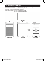
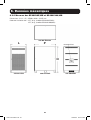
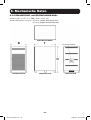
6. Mechanical Data
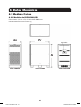
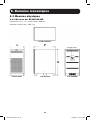
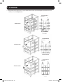
6.1 Physical Measurements
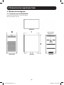
6.1.1 BP480V40/NIB Measurements
Dimensions (H x W x D): 1220 x 626 x 900 mm
Empty Cabinet Weight: 103.3 kg
TOP VIEW
BREAKER
FRONT VIEW
W D
H
SIDE VIEW REAR VIEW
18-09-176-933861.indb 12 9/26/2018 10:54:11 AM

13
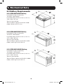
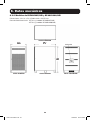
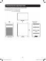
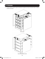
6.1.2 BP480V65/NIB and BP480V100/NIB Measurements
Dimensions (H x W x D): 1500 x 826 x 1135 mm
Empty Cabinet Weight: 157.6 kg (BP480V65/NIB model)
157.6 kg (BP480V100/NIB model)
6. Mechanical Data
TOP VIEW
BREAKER
FRONT VIEW
W D
H
SIDE VIEW REAR VIEW
18-09-176-933861.indb 13 9/26/2018 10:54:11 AM

14
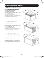
6. Mechanical Data
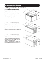
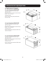
6.2 Battery Requirements
6.2.1 BP480V40/NIB Battery
Lead-Acid Cell Type and Quantity:
12V 40Ah x 40 Batteries
Lead-Acid Battery Maximum Size (H x W x L):
170 x 165 x 197 mm
Terminal Type: M6 Bolt
Terminal Torque (applies to CSB GP 12400
model): 59 kgf•cm/5.73 N•m
6.2.2 BP480V65/NIB Battery
Lead-Acid Cell Type and Quantity:
12V 65Ah x 40 Batteries
Lead-Acid Battery Maximum Size (H x W x L):
175 x 350 x 166 mm
Terminal Type: M6 Bolt
Terminal Torque (applies to CSB GPL 12650
model): 138.6 kgf•cm/13.58 N•m
6.2.3 BP480V100/NIB Battery
Lead-Acid Cell Type and Quantity:
12V 100Ah x 40 Batteries
Lead-Acid Battery Maximum Size (H x W x L):
217 x 170 x 343 mm
Terminal Type: M6 Bolt
Terminal Torque (applies to CSB GPL 121000
model): 138.6 kgf•cm/13.58 N•m
W
L
H
W
L
H
W
L
H
18-09-176-933861.indb 14 9/26/2018 10:54:12 AM

15
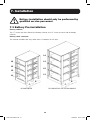
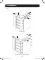
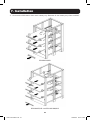
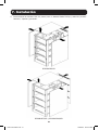
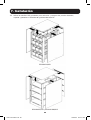
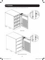
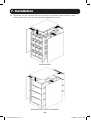
7. Installation
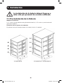
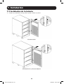
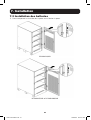
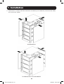
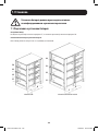
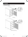
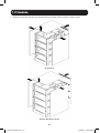
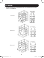
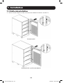
7.1 Battery Pre-Installation
Battery cabinet:
The “F” marks the front side of the battery cabinet; the “R” marks the rear side of battery
cabinet.
Battery shelf structure:
The cabinet includes four trays total from L1 (bottom) to L4 (top).
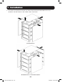
BP480V40/NIB BP480V65/NIB AND B480V100/NIB
Battery installation should only be performed by
qualified service personnel.
FF
RR
L1
L1
L2
L2
L3
L3
L4
L4
18-09-176-933861.indb 15 9/26/2018 10:54:12 AM

16
7. Installation
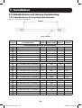
7.2 Cable Jumpers and Internal Wiring
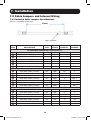
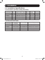
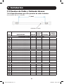
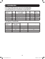
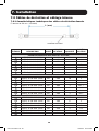
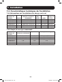
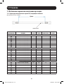
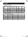
7.2.1 Included Cable Jumpers Specifications
50 mm
2
(1/0 AWG) double wire
ITEM DESCRIPTION UNIT
CABLE
LENGTH QUANTITY
CABLE
NUMBER
BP480V40/BP480V40-NIB (40Ah batteries)
1
#1 AWG CABLE (BLACK) mm 200 30 1
2
#1 AWG CABLE (BLACK) mm 350 2 2
3
#1 AWG CABLE (BLACK) mm 470 6 3
4
#1 AWG CABLE (BLACK) mm 900 1 BAT +
5
#1 AWG CABLE (BLACK) mm 600 1 N1
6
#1 AWG CABLE (BLACK) mm 320 1 N2
7
#1 AWG CABLE (BLACK) mm 300 1 BAT -
BP480V65/BP480V65-NIB (65Ah batteries)
1
#2/0 AWG CABLE (BLACK) mm 200 30 1
2
#2/0 AWG CABLE (BLACK) mm 300 6 2
3
#2/0 AWG CABLE (BLACK) mm 650 2 3
4
#2/0 AWG CABLE (BLACK) mm 800 1 BAT +
5
#2/0 AWG CABLE (BLACK) mm 450 1 N1
6
#2/0 AWG CABLE (BLACK) mm 800 1 N2
7
#2/0 AWG CABLE (BLACK) mm 500 1 BAT -
BP480V100/BP480V100-NIB (100Ah batteries)
1
#4/0 AWG CABLE (BLACK) mm 200 30 1
2
#4/0 AWG CABLE (BLACK) mm 300 6 2
3
#4/0 AWG CABLE (BLACK) mm 650 2 3
4
#4/0 AWG CABLE (BLACK) mm 800 1 BAT +
5
#4/0 AWG CABLE (BLACK) mm 450 1 N1
6
#4/0 AWG CABLE (BLACK) mm 800 1 N2
7
#4/0 AWG CABLE (BLACK) mm 500 1 BAT -
L(mm)
CABLE NUMBER
18-09-176-933861.indb 16 9/26/2018 10:54:12 AM

17
7. Installation
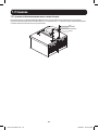
7.2.2 Installing Cable Jumpers to Battery Terminals
The BP480V40/BP480V65/BP480V100 battery cabinets and Tripp Lite batteries include
hardware to attach the cable jumpers to the batteries’ positive (+) and negative (-) terminals.
Refer to the illustration below for proper hardware installation.
Bolt
Lock Washer
Flat Washer
Cable
18-09-176-933861.indb 17 9/26/2018 10:54:12 AM

18
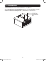
7. Installation
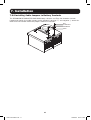
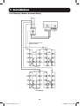
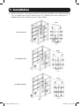
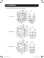
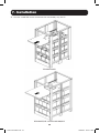
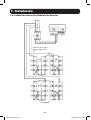
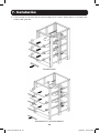
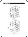
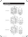
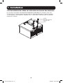
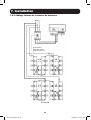
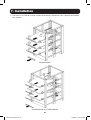
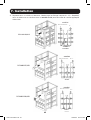
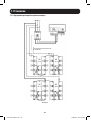
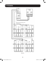
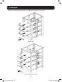
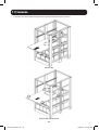
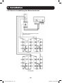
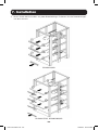
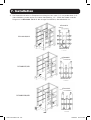
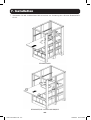
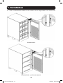
7.2.3 Battery Cabinet Internal Wiring
BP480V40
Input/Output Breaker
200A/250Vdc
L1 L2
L3 L4
18-09-176-933861.indb 18 9/26/2018 10:54:13 AM

19
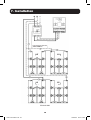
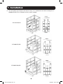
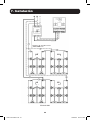
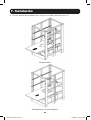
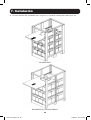
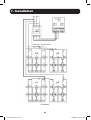
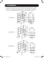
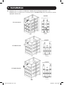
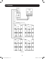
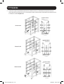
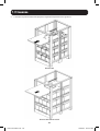
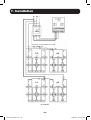
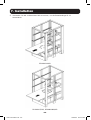
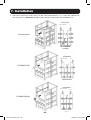
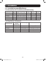
7. Installation
BP480V65
Input/Output Breaker
300A/600Vdc
L1 L2
L3 L4
18-09-176-933861.indb 19 9/26/2018 10:54:13 AM

20
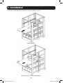
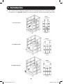
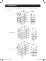
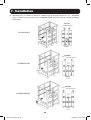
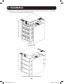
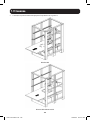
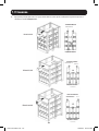
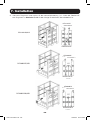
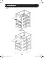
7. Installation
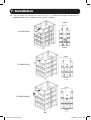
BP480V100
Input/Output Breaker
400A/600Vdc
L1 L2
L3 L4
18-09-176-933861.indb 20 9/26/2018 10:54:13 AM
Seite wird geladen ...
Seite wird geladen ...
Seite wird geladen ...
Seite wird geladen ...
Seite wird geladen ...
Seite wird geladen ...
Seite wird geladen ...
Seite wird geladen ...
Seite wird geladen ...
Seite wird geladen ...
Seite wird geladen ...
Seite wird geladen ...
Seite wird geladen ...
Seite wird geladen ...
Seite wird geladen ...
Seite wird geladen ...
Seite wird geladen ...
Seite wird geladen ...
Seite wird geladen ...
Seite wird geladen ...
Seite wird geladen ...
Seite wird geladen ...
Seite wird geladen ...
Seite wird geladen ...
Seite wird geladen ...
Seite wird geladen ...
Seite wird geladen ...
Seite wird geladen ...
Seite wird geladen ...
Seite wird geladen ...
Seite wird geladen ...
Seite wird geladen ...
Seite wird geladen ...
Seite wird geladen ...
Seite wird geladen ...
Seite wird geladen ...
Seite wird geladen ...
Seite wird geladen ...
Seite wird geladen ...
Seite wird geladen ...
Seite wird geladen ...
Seite wird geladen ...
Seite wird geladen ...
Seite wird geladen ...
Seite wird geladen ...
Seite wird geladen ...
Seite wird geladen ...
Seite wird geladen ...
Seite wird geladen ...
Seite wird geladen ...
Seite wird geladen ...
Seite wird geladen ...
Seite wird geladen ...
Seite wird geladen ...
Seite wird geladen ...
Seite wird geladen ...
Seite wird geladen ...
Seite wird geladen ...
Seite wird geladen ...
Seite wird geladen ...
Seite wird geladen ...
Seite wird geladen ...
Seite wird geladen ...
Seite wird geladen ...
Seite wird geladen ...
Seite wird geladen ...
Seite wird geladen ...
Seite wird geladen ...
Seite wird geladen ...
Seite wird geladen ...
Seite wird geladen ...
Seite wird geladen ...
Seite wird geladen ...
Seite wird geladen ...
Seite wird geladen ...
Seite wird geladen ...
Seite wird geladen ...
Seite wird geladen ...
Seite wird geladen ...
Seite wird geladen ...
Seite wird geladen ...
Seite wird geladen ...
Seite wird geladen ...
Seite wird geladen ...
Seite wird geladen ...
Seite wird geladen ...
Seite wird geladen ...
Seite wird geladen ...
Seite wird geladen ...
Seite wird geladen ...
Seite wird geladen ...
Seite wird geladen ...
Seite wird geladen ...
Seite wird geladen ...
Seite wird geladen ...
Seite wird geladen ...
Seite wird geladen ...
Seite wird geladen ...
Seite wird geladen ...
Seite wird geladen ...
Seite wird geladen ...
Seite wird geladen ...
Seite wird geladen ...
Seite wird geladen ...
Seite wird geladen ...
Seite wird geladen ...
Seite wird geladen ...
Seite wird geladen ...
Seite wird geladen ...
Seite wird geladen ...
Seite wird geladen ...
Seite wird geladen ...
Seite wird geladen ...
Seite wird geladen ...
Seite wird geladen ...
Seite wird geladen ...
Seite wird geladen ...
Seite wird geladen ...
Seite wird geladen ...
Seite wird geladen ...
Seite wird geladen ...
Seite wird geladen ...
Seite wird geladen ...
Seite wird geladen ...
Seite wird geladen ...
Seite wird geladen ...
Seite wird geladen ...
Seite wird geladen ...
Seite wird geladen ...
Seite wird geladen ...
Seite wird geladen ...
Seite wird geladen ...
Seite wird geladen ...
Seite wird geladen ...
Seite wird geladen ...
Seite wird geladen ...
Seite wird geladen ...
Seite wird geladen ...
Seite wird geladen ...
Seite wird geladen ...
Seite wird geladen ...
Seite wird geladen ...
Seite wird geladen ...
Seite wird geladen ...
Seite wird geladen ...
Seite wird geladen ...
Seite wird geladen ...
Seite wird geladen ...
Seite wird geladen ...
Seite wird geladen ...
Seite wird geladen ...
Seite wird geladen ...
Seite wird geladen ...
Seite wird geladen ...
Seite wird geladen ...
Seite wird geladen ...
-
 1
1
-
 2
2
-
 3
3
-
 4
4
-
 5
5
-
 6
6
-
 7
7
-
 8
8
-
 9
9
-
 10
10
-
 11
11
-
 12
12
-
 13
13
-
 14
14
-
 15
15
-
 16
16
-
 17
17
-
 18
18
-
 19
19
-
 20
20
-
 21
21
-
 22
22
-
 23
23
-
 24
24
-
 25
25
-
 26
26
-
 27
27
-
 28
28
-
 29
29
-
 30
30
-
 31
31
-
 32
32
-
 33
33
-
 34
34
-
 35
35
-
 36
36
-
 37
37
-
 38
38
-
 39
39
-
 40
40
-
 41
41
-
 42
42
-
 43
43
-
 44
44
-
 45
45
-
 46
46
-
 47
47
-
 48
48
-
 49
49
-
 50
50
-
 51
51
-
 52
52
-
 53
53
-
 54
54
-
 55
55
-
 56
56
-
 57
57
-
 58
58
-
 59
59
-
 60
60
-
 61
61
-
 62
62
-
 63
63
-
 64
64
-
 65
65
-
 66
66
-
 67
67
-
 68
68
-
 69
69
-
 70
70
-
 71
71
-
 72
72
-
 73
73
-
 74
74
-
 75
75
-
 76
76
-
 77
77
-
 78
78
-
 79
79
-
 80
80
-
 81
81
-
 82
82
-
 83
83
-
 84
84
-
 85
85
-
 86
86
-
 87
87
-
 88
88
-
 89
89
-
 90
90
-
 91
91
-
 92
92
-
 93
93
-
 94
94
-
 95
95
-
 96
96
-
 97
97
-
 98
98
-
 99
99
-
 100
100
-
 101
101
-
 102
102
-
 103
103
-
 104
104
-
 105
105
-
 106
106
-
 107
107
-
 108
108
-
 109
109
-
 110
110
-
 111
111
-
 112
112
-
 113
113
-
 114
114
-
 115
115
-
 116
116
-
 117
117
-
 118
118
-
 119
119
-
 120
120
-
 121
121
-
 122
122
-
 123
123
-
 124
124
-
 125
125
-
 126
126
-
 127
127
-
 128
128
-
 129
129
-
 130
130
-
 131
131
-
 132
132
-
 133
133
-
 134
134
-
 135
135
-
 136
136
-
 137
137
-
 138
138
-
 139
139
-
 140
140
-
 141
141
-
 142
142
-
 143
143
-
 144
144
-
 145
145
-
 146
146
-
 147
147
-
 148
148
-
 149
149
-
 150
150
-
 151
151
-
 152
152
-
 153
153
-
 154
154
-
 155
155
-
 156
156
-
 157
157
-
 158
158
-
 159
159
-
 160
160
-
 161
161
-
 162
162
-
 163
163
-
 164
164
-
 165
165
-
 166
166
-
 167
167
-
 168
168
-
 169
169
-
 170
170
-
 171
171
-
 172
172
-
 173
173
-
 174
174
-
 175
175
-
 176
176


Tripp Lite Extended-Run Battery Cabinet Bedienungsanleitung
- Kategorie
- Wiederaufladbare Batterien
- Typ
- Bedienungsanleitung
in anderen Sprachen
Verwandte Artikel
-
Tripp Lite Extended-Run Battery Cabinet Bedienungsanleitung
-
-
-
-
-
-
Tripp Lite S3M30KX, S3M40KX, S3M60KX, S3M80KX Bedienungsanleitung
-
Tripp-Lite CSCXS36AC Bedienungsanleitung
-
Tripp Lite S3M30KX, S3M40KX, S3M60KX, S3M80KX Bedienungsanleitung
-