
Art.-Nr. 1005383, 1006613 04/2022
© SLV GmbH
Daimlerstr. 21-23, 52531 Übach-Palenberg, Deutschland
Tel. +49 (0)2451 4833-0
Technische Änderungen vorbehalten. UCB-LBV60WZ-SL01
Beschreibung und Einbauanweisung
LED Driver mit konstanter Ausgangsspannung zum Betreiben von LEDs
(Elektronisches Schaltnetzteil)
Typen: 1005383, 1006613
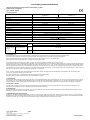
1. Technische Daten:
Art.-Nr.
1005383
LBV60W24-Z
1006613
LBV60W48-Z
Nennspannung
220–240 V 50–60 Hz
Nennstrom
310 mA
Netzleistungsfaktor
0,95
Teillastbereich
0–60 W
Konstante Ausgangsspannung
24 Vdc SELV
48 Vdc SELV
Ausgangsstrom
2500 mA max.
1250 mA max.
Leerlaufspannung
25 V max.
49 V max.
Schutzklasse
II
Schutzart
IP20
Leerlaufsicherheit
gewährleistet
Kurzschluss- und Überlastschutz
elektronische Abschaltung mit automatischem Wiederanlauf
Umgebungstemperatur ta
-20 °C – +45 °C
Gehäusetemperatur tc-Punkt
max. 85 °C
max. 90 °C
Normen
EN 61347, EN 62384, EN 62493
EN 61547, EN 55015, EN 61000-3-2, EN 61000-3-3
Leitung (Zugentlastung)
PRI
SEC
H03VV(H2)-F 2x0,75 / 1,0 mm², H05VV(H2)-F 2x0,75 / 1,0 mm²
Zugentlastung / Klemmbereich
2–5,5 mm
Leitungs-konfektio
nierung
(Klemmen)
Leitungsquerschnitt
PRI
SEC
0,75–1,5 mm²
AWG 18–16
Abisolierlänge
PRI
SEC
9 mm
2. Einbauhinweise
Die Installation darf nur durch eine Elektrofachkraft in Übereinstimmung mit internationalen und nationalen Normen ausgeführt werden.
Der Schutz gegen elektrischen Schlag ist bei Arbeiten an elektrischen Anlagen durch Freischalten der Anlage sicherzustellen.
Primär- und Sekundärleitungen kreuzungsfrei verlegen (Funkschutz). Die Verdrahtung so kurz wie möglich halten.
Die maximale Länge der Ausgangsleitung von 2 m darf nicht überschritten werden.
Vor der Einschaltung der Netzspannung ist dafür zu sorgen, dass alle LEDs komplett verdrahtet und angeschlossen sind!
Die LED Driver sind nur zur Verwendung mit LEDs bestimmt, die eine Konstantspannung von 24/48 Vdc benötigen. Bei falscher Ausgangsspannung können die LEDs
und/oder der Treiber zerstört werden. Beim Anschließen der LEDs ist darauf zu achten, dass + und – auf die richtigen Klemmen beim LED Treiber aufgelegt werden.
Das LED-Betriebsgerät besitzt keinen sekundärseitigen Verpolschutz. LED-Module können bei Verpolung zerstört werden.Hierfür wird keine Garantie übernommen.
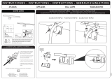
Bei außerhalb von Leuchten montiertem LED Driver ist auf eine korrekte Befestigung der Primär- und Sekundärleitungen in den Zugentlastungen zu achten und er ist
über seine Anschraublöcher auf dem jeweiligen Untergrund fest zu verschrauben.
Die ta- oder die tc-Temperatur darf in keiner Einbauweise überschritten werden. Die angegebenen Mindestabstände sind Richtlinien und von der eingesetzten
Leuchte bzw. Umgebung abhängig (siehe letzte Seite).
Die Geräte enthalten keine servicefähigen Bauteile und dürfen daher nicht geöffnet werden.
Der LED Treiber ist nicht über elnen Phasenan- oder abschnittdimmer regelbar!
3. Überspannung
Die LED Treiber sind surgespannungsfest entsprechend der von der einschlägigen Norm vorgeschriebenen Werte. Zum Schutz vor höheren Überspannungen, die z.B.
beim Schalten von Leuchtstofflampen und Entladungslampen mit induktivem Vorschaltgerät, Motoren (Ventilatoren, usw.) und anderen induktiven Lasten auftreten,
sind die Lastkreise für diese Gerätegruppen deutlich voneinander zu trennen und unter Umständen weitere Massnahmen (überspannungsableiter) erforderlich.
4. Kurzschluss / Überlast
Der LED Treiber schaltet bei Kurzschluss oder Überlast automatisch ab. Er besitzt keine Sicherung herkömmlicher Art. Der Laststromkreis wird folglich nicht
aufgetrennt! Nach Beheben des Fehlers schaltet der LED Driver automatisch wieder ein.
5. Übertemperatur
Bei Übertemperatur durch externe Wärmequellen oder unzulässige Abdeckungen erfolgt eine Funktionsunterbrechung. Eine Netzfreischaltung erfolgt nicht. Nach
Abkühlung schaltet der LED Driver automatisch wieder ein.
6. Wärmeableitung bzw. Wärmeübergang
Ein Betrieb in überhöhter Umgebungstemperatur oder durch Fremderwärmung verkürzt die Lebensdauer. Beim Einbau (vor allem in Leuchten) ist durch geeignete
Maßnahmen für eine Wärmeabfuhr (Wärmeübergang) zu sorgen. Die Umgebungstemperatur und/oder Tc-Punkt Temperatur darf zu keinem Zeitpunkt überschritten
werden. Für Schäden, die aus entsprechend unsachgemäßem Gebrauch entstehen, wird keine Haftung übernommen.

Art.-No. 1005383, 1006613 04/2022
© SLV GmbH
Daimlerstr. 21-23, 52531 Übach-Palenberg, Germany
Tel. +49 (0)2451 4833-0
Technical properties subject to modification.
Description and Mounting Instructions
LED Driver with constant output voltage for the operation of LED
(Electronic power supply unit)
Types: 1005383, 1006613
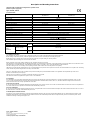
1. Technical Data:
Art.-No.
1005383
LBV60W24-Z
1006613
LBV60W48-Z
Rated voltage
220–240 V 50–60 Hz
Rated current
310 mA
Power Factor
0.95
Shared load operation
0–60 W
Constant output voltage
24 Vdc SELV
48 Vdc SELV
Secondary current
2500 mA max.
1250 mA max.
Open circuit voltage
25 V max.
49 V max.
Protection class
II
Degree of protection
IP20
Open circuit safety
guaranteed
Short circuit and overload protection
electronic disconnection with automatic restart
Ambient temperature ta
-20 °C – +45 °C
Case temperature tc-point
max. 85 °C
max. 90 °C
Standards
EN 61347, EN 62384, EN 62493
EN 61547, EN 55015, EN 61000-3-2, EN 61000-3-3
Cable (Strain relief)
PRI
SEC
H03VV(H2)-F 2x0.75 / 1.0 mm², H05VV(H2)-F 2x0.75 / 1.0 mm²
Strain relief / Clamping range
2–5.5 mm
Cable
(Terminals)
Diameter of wires
PRI
SEC
0.75–1.5 mm²
AWG 18–16
Bared wire end
PRI
SEC
9 mm
2. Installation Instructions
The installation may only be carried out by an electrical specialist in accordance with international and national standards.
When working on electrical systems, protection against electric shock is to be ensured by disconnecting the system.
Install primary and secondary mains intersection-free (RFI protection). Keep the wiring as short as possible.
The maximum output wire length of 2 m must not be exceeded.
Before switching on the supply voltage all LED must be completely wired and connected!
The LED Driver is strictly suited for the use with LED that requires a constant voltage of 24/48 Vdc. If the output voltage is incorrect, the LEDs and / or the driver can be
destroyed. When connecting the LED, careful attention should be paid to connecting + and - to the right terminals on the LED Driver.
The LED control gear has no secondary reverse polarity protection. LED modules can be destroyed in reverse polarity.
LED Drivers mounted outside of luminaires are to be screwed tightly to the respective surface by their screw holes and careful attention is to be paid to the connecting
cables and the lamp cables being fastened securely in the strain relief.
The ta or tc temperature may not be exceeded for any kind of mounting. The specified minimum distances are guidelines and dependent upon of the used
luminaire or environment (see last page).
The devices do not contain any serviceable components and may not be opened.
The LED Driver cannot be regulated via a phase cut-on or cut-off dimmer!
3. Overvoltage
Our LED Drivers are surge-voltage-stable with values above those prescribed by the respective standards. As a protection against high voltage surges, as they
occur e.g. when switching fluorescent lamps and discharge lamps with an inductive ballast, motors (fans, etc.) and other inductive charges, the load circuits for
devices of this kind are to be clearly separated from each other.
4. Short circuit / overload
In case of a short circuit or overload the LED Driver will automatically cut off. It does not have a fuse of the conventional kind. Thus the load circuit is not separated! As
soon as the defect has been repaired, the LED Driver will automatically cut back in.
5. Excess Temperature
In case of excess temperature through external heat sources or impermissible covers the function will be interrupted. The mains will not be disconnected. As soon as
the LED Driver has cooled off, it will automatically cut back in.
6. Heat Dissipation and Heat Transfer
Operation in excess ambient temperature or through external heating will reduce the service life. During the installation process (particularly into luminaires), heat
dissipation (heat transfer) is to be provided through suitable measures. The ambient temperature and/or tc temperature may not be exceeded at any time. We are
not liable for damage resulting from improper use.

No. de commande 1005383, 1006613 04/2022
© SLV GmbH
Daimlerstr. 21-23, 52531 Übach-Palenberg, Allemagne
Tel. +49 (0)2451 4833-0
Sous réserve de modifications techniques.
Description et instructions de montage
Pilote de diodes à tension de sortie constant pour l'utilisation de diodes
(Bloc d'alimentation électronique)
Type: 1005383, 1006613
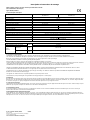
1. Caractéristiques techniques:
No. de commande
1005383
LBV60W24-Z
1006613
LBV60W48-Z
Tension nominale
220–240 V 50–60 Hz
Courant nominal
310 mA
Facteur de puissance
0,95
Plage de charge partielle
0–60 W
Tension de sortie constante
24 Vdc SELV
48 Vdc SELV
Courant secondaire
2500 mA max.
1250 mA max.
Tension en circuit ouvert
25 V max.
49 V max.
Classe de protection
II
Degré de protection
IP20
Sécurité à vide
garantie
Protection contre les courts-circuits et les surcharges
mise hors circuit électronique à redémarrage automatique
Température ambiante ta
-20 °C – +45 °C
Température du boîtier (point tc)
max. 85 °C
max. 90 °C
Norms
EN 61347, EN 62384, EN 62493
EN 61547, EN 55015, EN 61000-3-2, EN 61000-3-3
Câble (Décharge de traction)
PRI
SEC
H03VV(H2)-F 2x0,75 / 1,0 mm², H05VV(H2)-F 2x0,75 / 1,0 mm²
Collier de fixation / Plage de serrage
2–5,5 mm
Câble
(Bornes)
Diamètre de
conducteur
PRI
SEC
0,75–1,5 mm²
AWG 18–16
Longeur d’alimentation
PRI
SEC
9 mm
2. Conseil pour l'encastrement
L'installation ne doit être effectuée que par un expert en électrotechnique et en conformité avec les normes nationales et internationales.
Lors de travaux aux installations électriques, la protection contre les décharges électriques doit être assurée en mettant l'installation hors tension.
Monter les circuits primaires et secondaires en évitant qu'ils ne se croissent (protection contre le parasitage).
La sortie maximale d‘un câble de 2 m de long ne doit pas être dépassée.
Avant de mettre sous tension, toutes les LED doivent être complètement câblées et connectées!
Le driver de LED est strictement adapté à une utilisation avec des LED nécessitant un tension constante de 24/48 Vdc. Si la tension de sortie est incorrecte, les LED et
/ ou le pilote peuvent être détruits. Lors du raccordement de la LED, veillez à connecter les bornes + et - aux bornes de droite du driver de LED.
Le ballast LED n’a aucune protection secondaire contre la polarité inversée. Les modules LED peuvent être détruits en polarité inverse.
Lorsque le Convertisseur LED est fixé à l’extérieur du luminaire, veiller à ce que les circuits primaire et secondaire soient correctement fixés dans les colliers.
Ce LED driver doit être fermement maintenu sur son support par des vis placées dans les trous de vissage.
La température ta ou tc ne doit pas être dépassée pour tout type de montage. Les distances minimales spécifiées sont indicatives et dépendent de l’utilisation
luminaire ou environnement (voir dernière page).
Les appareils ne contiennent aucun composant réparable et ne peuvent pas être ouverts.
Le LED Driver ne peut pas être régulé via un gradateur à découpage de phase ou à découpage!
3. Surtension
Nos LED drivers résistent à la tension surge au-delà des valeurs prescrites par la norme afférente. Pour assurer la protection contre les surtensions supérieures qui se
forment, par ex. lors de l'allumage de lampes fluorescentes et de lampes à décharge à ballast à induction, de moteurs (ventilateurs, etc.) et autres charges inductives,
les circuits de charge de ces groupes d'appareils doivent être clairement séparés les uns par rapport aux autres.
4. court-circuit / surcharge
Le LED-Driver se déclenche automatiquement en cas de court-circuit ou de surcharge. Il n'est pas équipé d'un fusible classique. De ce fait, le circuit de charge n'est pas
défait ! Dès que la panne est réparée, le LED Driver se réenclenche automatiquement.
5. Température excessive
En cas de température excessive par des sources extérieures de chaleur ou des couvertures interdites la fonction sera interrompue. Les forces ne seront pas
déconnectées. LED driver se réenclenche automatiquement.
6. Dissipation thermique et transfert de chaleur
Toute utilisation en cas de température d'ambiance excessive, ou de réchauffement extérieur, réduit la durée de vie. En cas d'encastrement (notamment dans des
luminaires), il faut assurer la dissipation (le transfert) thermique en prenant des mesures adéquates. La température ambiante et/ou la température point tc ne peuvent
être dépassées en aucun cas. Nous n'assumons aucune responsabilité pour des dégâts survenus suite à une utilisation non conforme.

No. Ped. 1005383, 1006613 04/2022
© SLV GmbH
Daimlerstr. 21-23, 52531 Übach-Palenberg, Alemania
Tel. +49 (0)2451 4833-0
Salvo modificaciónes técnicas.
Especificación y instrucciones de montaje
Convertidor de LED con tensión de salida constante para la alimentación de LED
(Convertidor electrónico)
Tipos: 1005383, 1006613
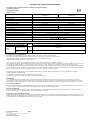
1. Datos técnicos:
No. Ped.
1005383
LBV60W24-Z
1006613
LBV60W48-Z
Tensión nominal
220–240 V 50–60 Hz
Corriente nominal
310 mA
Factor de potencia
0,95
Funcionamiento con carga compartida
0–60 W
Tensión de salida constante
24 Vdc SELV
48 Vdc SELV
Corriente secundario
2500 mA max.
1250 mA max.
Tensión en circuito abierto
25 V max.
49 V max.
Clase de protección
II
Grado de protección
IP20
Seguridad en circuito abierto
garantía
Protección contra cortocircuito y sobrecarga
desconexión electrónica con rearranque automático
Temperatura ambiente ta
-20 °C – +45 °C
Temperatura de la caja punto tc
max. 85 °C
max. 90 °C
Normas
EN 61347, EN 62384, EN 62493
EN 61547, EN 55015, EN 61000-3-2, EN 61000-3-3
Cable (Descarga de tracción)
PRI
SEC
H03VV(H2)-F 2x0,75 / 1,0 mm², H05VV(H2)-F 2x0,75 / 1,0 mm²
Descarga de tracción / Área de sujeción
2–5,5 mm
Cable
(Borna)
Diametro de los hilos
PRI
SEC
0,75–1,5 mm²
AWG 18–16
Extremo del hilo
pelado
PRI
SEC
9 mm
2. Instrucciones de montaje importantes
La instalación sólo debe realizarse por un electricista conforme a las normas nacionales e internacionales.
Para la protección contra eléctrochoques hay que desconectar los equipos eléctricos durante los trabajos en ellos.
Tender las líneas primarias y secundarias sin cruzarlas. (Protección contra radiointerferencias).
La longitud máxima del hilo de salida no se debe superar 2 m.
¡Antes de encender la tensión de red, asegúrese de que todos los LED estén completamente conectados y conectados!
Los controladores de LED solo están diseñados para usarse con LED que requieren un voltaje constante de 24/48 Vdc. Si el voltaje de salida es incorrecto, los LED y
/ o el controlador pueden destruirse. Al conectar los LED, asegúrese de que + y - estén conectados a los terminales correctos en el controlador de LED.
El equipo de control LED no tiene protección contra polaridad inversa. Los módulos LED se pueden destruir si se invierte la polaridad y no se ofrece ninguna garantía.
Para los convertidores de LED montados fuera de la luminaria hay que estar pendiente de la fijación correcta de las lineas primarias y secundarias en los puestos de
Sujeción de tracción.Hay que atornillar el convertidor de LED por sus huecos de fijación en la base respectiva.
No se puede exceder la temperatura ta o tc para ningún tipo de montaje. Las distancias mínimas especificadas son pautas y dependen de las utilizadas
luminaria o ambiente (ver última página).
Los dispositivos no contienen componentes reparables y no se pueden abrir.
¡El controlador LED no se puede regular a través de un atenuador de corte o de fase!
3. Sobretensión
Los convertidores de LED son resistentes contra las sobretensiónes transitorias hasta valores que pasan con mucho aquellos especificados por las normas
correspondientes. Para la protección contra sobretensiones que se presentan por ejemplo cuando se conmutan lámparas fluorescentes y lámparas de descarga con
balasto inductivo, motores (ventiladores, etc.) y otras cargas inductivas, hay que separar claramente los circuitos de carga para esta serie de equipos uno de otro.
4. Cortocircuito / sobrecarga
El convertidor de LED se desconecta automáticamente en caso de un cortocircuito o de sobrecarga. No tiene ningun cortacircuito convencional. ¡En consecuencia, el
circuito de carga no se separa! Al remediar el fallo el convertidor de LED se conecta automáticamente de nuevo.
5. Exceso de temperatura
En caso de exceso de temperatura a través de fuentes de calor externas o de cubiertas inadmisible la función sera interrumpida. La red no sera desconectada..
Después del enfriamiento el convertidor de LED se conecta automáticamente de nueveo.
6. Disipación de calor y transferencia de calor
La operación en temperatura ambiente muy elevada o por calentamiento externo reduce la vida. Durante el montaje ( sobre todo en luminarias ) hay que procurar, por
medidas apropiadas, una disipación de calor ( transferencia de calor ). No se debe pasar en ningún momento la temperatura ambiente y / o la temperatura punto tc. No
se asume ninguna responsabilidad de daños originados por uso inadecuado.

Type Nr. 1005383, 1006613 04/2022
© SLV GmbH
Daimlerstr. 21-23, 52531 Übach-Palenberg, Duitsland
Tel. +49 (0)2451 4833-0
Technische veranderingen onder voorbehoud.
Beschrijving en montageaanwijzing
LED driver met constante uitgangsspanning voor het bedrijf van LED
(Elektronische schakelaar nettransformator)
Type Nr: 1005383, 1006613
1. Technische gegevens:
Type Nr.
1005383
LBV60W24-Z
1006613
LBV60W48-Z
Nominale spanning
220–240 V 50–60 Hz
Nominale stroom
310 mA
Arbeidsfactor
0,95
Deellastbereik
0–60 W
Constante uitgangsspanning
24 Vdc SELV
48 Vdc SELV
Secundair stroom
2500 mA max.
1250 mA max.
Onbelaste secundair spanning
25 V max.
49 V max.
Veiligheidsklasse
II
Beveiligingsgraad
IP20
Beveiligd tegen leegloop
gegarandeerd
Beveiligd tegen kortsluiting en overlast
elektronisch uitschakelen met automatisch herinschakelen
Omgevingstemperatuur ta
-20 °C – +45 °C
Kasttemperatuur tc-punt
max. 85 °C
max. 90 °C
Normen
EN 61347, EN 62384, EN 62493
EN 61547, EN 55015, EN 61000-3-2, EN 61000-3-3
Kabel (Trekontlasting)
PRI
SEC
H03VV(H2)-F 2x0,75 / 1,0 mm², H05VV(H2)-F 2x0,75 / 1,0 mm²
Trekontlasting / Klembereik
2–5,5 mm
Kabel
(Klemmen)
Draaddiameter
PRI
SEC
0,75–1,5 mm²
AWG 18–16
Striplengte
PRI
SEC
9 mm
2. Belangrijke informatie
De installatie mag alleen worden uitgevoerd door een vakkundige elektricien en overeenkomstig met de internationale en nationale normen.
De bescherming tegen elektrische schokken is tijdens het werken met elektrische installaties door het afkoppelen van de installatie te waarborgen.
Primaire en secundaire leidingen niet kruisgewijs aansluiten (elektromagnetische storingen).
De maximale lengte van de uitgangsdraad van 2 m mag niet worden overschreden.
Voordat u de voedingsspanning inschakelt, moet alle LED volledig bedraad en aangesloten zijn!
De LED-drivers zijn alleen bedoeld voor gebruik met LED's die een constante spanning van 12/24/48 Vdc vereisen.
Bij een onjuiste uitgangsspanning kunnen de leds en / of de driver kapot gaan. Zorg er bij het aansluiten van de LED's voor dat + en - zijn aangesloten op de juiste
klemmen op de LED-driver. De LED-voorschakelapparatuur heeft geen bescherming tegen omgekeerde polariteit. LED-modules kunnen worden vernietigd als de
polariteit wordt omgekeerd en er wordt geen garantie gegeven.
Als de LED driver buiten de lamp geinstalleerd wordt moet erop worden gelet dat de primaire en secundaire leidingen in de trekontlasting correct gemonteerd
Worden. Bovendien moet de aandrijving door de ervoor bestemde gaten vast op de ondergrond geschroefd worden.
De Ta- of TC-temperatuur mag voor geen enkele montage worden overschreden. De opgegeven minimale afstanden zijn richtlijnen en afhankelijk van de gebruikte
armatuur of omgeving (zie laatste pagina).
De apparaten bevatten geen onderdelen die kunnen worden onderhouden en mogen niet worden geopend.
De LED-driver kan niet worden geregeld via een fase-inschakeling of uitschakeling-dimmer!
3. Overspanning
Onze LED drivers zijn beschermd tegen overspanning tot over de van de desbetreffende norm voorgeschreven waarden. Als bescherming tegen hogere
overspanningen, die bijv. kunnen ontstaan bij het inschakelen van tl-buizen en ontladingslampen met inductieve voorschakelapparaten, motoren (ventilatoren, etc.) en
andere inductieve apparaten, moeten de belastingscircuits voor deze groepen van apparaten duidelijk van elkaar gescheiden worden.
4. Kortsluiting / overbelasting
In geval van kortsluiting of overbelasting schakelt de LED Driver automatisch uit. Het heeft geen conventionele lont. Het belastingscircuit is dus niet gescheiden! Zodra
het defect is gerepareerd, schakelt de LED-driver automatisch in.
5. Overtollige temperatuur
Bij te hoge temperaturen, veroorzaakt door extrene warmtebronnen, of ontoelaatbare afdekking, zal de ingebouwde temperatuurcontrole het vermogen verlagen. Na
het afkoelen wordt de LED driver automatisch weer ingeschakeld.
6. Warmte consumptie en warmteoverdracht
Het bedrijf in een te hoge omgevingstemperatuur of externe verwarming verkort de levensduur. Bij het inbouwen (vooral in lichten), moet door passende maatregelen
voor warmteafvoer (warmteovergang) gezorgd worden. De omgevingstemperatuur en/of de temperatuur tc-punt mag nooit worden overschreden. Wij zijn niet
verantwoordelijk voor schade als gevolg van onjuiste gebruik.

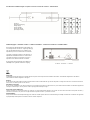
Anschlussbild - Installation diagram - Esquema de conexión - Schéma de connexion – Aansluitschema
Einbaubedingungen – Installation condition – Conditions d'installation – Condiciones de instalación – Installatiecondities
Die angegebenen Mindestabstände sind Richtlinien und
von der eingesetzten Leuchte bzw. Umgebung abhängig.
The specified minimum distances are guidelines and
dependent upon of the used luminaire or environment.
Les distances minimales spécifiées sont indicatives et
dépendent de l’utilisation luminaire ou environnement
Las distancias mínimas especificadas son pautas y
dependen de las utilizadas luminaria o ambiente
De opgegeven minimale afstanden zijn richtlijnen en
afhankelijk van de gebruikte armatuur of omgeving
A >50 mm B >50 mm C > 100 mm
(WEEE)
Entsorgung
Produkt nicht im Hausmüll entsorgen! Produkte mit diesem Symbol sind entsprechend der Richtlinie über Elektro- und Elektronik-Altgeräte über die örtlichen
Sammelstellen für Elektro-Altgeräte zu entsorgen!
Disposal
Do not dispose the product with the regular household waste! Products marked with this sign must be disposed according to the directive on electrical and electronic
devices at local collection points for such devices!
Information de recyclage
Ne recyclez pas le produit avec les ordures ménagères ! Les produits qui présentent ce symbole sont à recycler suivant la directive relative aux déchets d'équipements
électriques et électroniques, via des points de collecte pour appareils électriques usagés !
Indicaciones para la eliminación
¡No tirar el producto con la basura doméstica! Los productos con este símbolo deben eliminarse, de acuerdo con la directiva sobre residuos de aparatos eléctricos y
electrónicos, llevándolos a los puntos de recogida selectiva de aparatos eléctricos y electrónicos locales.
Afvalverwijdering
Het product niet via het huishoudelijk afval weggooien! Producten met dit symbool dienen in overeenstemming met richtlijn via elektrische en elektronische apparatuur
bij de plaatselijke inzamelpunten voor elektrisch afval te worden verwijderd!
220-240 V
Spannungsversorgung
Voltage supply
Tension d’éntrée
Tensión de entrada
Spanningvoorziening
-
 1
1
-
 2
2
-
 3
3
-
 4
4
-
 5
5
-
 6
6


in anderen Sprachen
- English: SVL 1006613 Owner's manual
- français: SVL 1006613 Le manuel du propriétaire
- español: SVL 1006613 El manual del propietario
- Nederlands: SVL 1006613 de handleiding
Verwandte Artikel
-
SVL 1006614 Bedienungsanleitung
-
-
-
-
-
-
-
-
-
Andere Dokumente
-
Ledco MODRIAN LED GU10 1x8W Wall Lamp Benutzerhandbuch
-
Bailey T8 EM+AC LED Party Benutzerhandbuch
-
 Ledco 16-3561 DUSTIN Benutzerhandbuch
-
-
Recom RACV06-12-LP Installationsanleitung
-
FLOS Light Shadow PRO 90 Adjustable Installation and Use Manual
