Intellinet 508834 Quick Instruction Guide
- Typ
- Quick Instruction Guide


2
The Intellinet 8-Port Gigabit Ethernet Layer 2+ Web-Managed Industrial Switch with 2 SFP Ports offers
an array of time-saving, cost-effective features while providing superior network throughput.
Features
• Provides RJ45 data connections for up to eight network devices
• IP30 slim-type metal housing to withstand harsh industrial conditions
• Wide operating temperature: -40 – 85°C (-40 – 185°F)
• Option for DIN-rail installation
• Two small form-factor pluggable GBIC module slots (SFP)
• Two redundant DC inputs (44 – 57 V) with I/O terminal block
With a backplane speed of 20 Gbps, plenty of performance is available for your computers, servers
and other networking devices. Each of the ports automatically senses the link speed of the connected
network device and adjusts to 10, 100 or 1000 Mbps for compatibility and maximum performance.
For the user manual and specifications, visit intellinetnetwork.com. Register your product
at register.intellinet-network.com/r/508834 or scan the QR code on the cover.
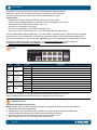
LEDs
LED Color Status Status Description
PWR Green On Power on
Off Power off; abnormal power
PWR1 &
PWR 2 Green On PWR input has power
Off Power is off or is working abnormally
Link/ACT
1 – 8
Green
(10/100 Mbps)
On Valid port connection (10/100 Mbps)
Blinking Sending or receiving data
Off No link established or port is connected at 1000 Mbps speed
Speed Green
(1000 Mbps)
On Valid port connection (1000 Mbps)
Off No link established or port is connected at 10/100 Mbps speed
SFP
1 & 2 Green
On Valid port connection
Blinking Sending or receiving data
Off No link established
Cat5e/6/6a UTP/STP cables provide optimal performance; if a status LED doesn’t indicate
a link or activity, check the corresponding device for proper setup and operation.
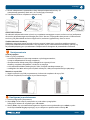
Power
Terminal Block Installation
NOTE: Ensure all power is off/disconnected before beginning!
1 Loosen appropriate screws.
2 Insert bare power-supply wires into appropriate terminal slots (positive
wire into positive slot; negative wire into negative slot).
3 Tighten appropriate screws to secure wires. (If desired, repeat steps 1 – 3 on second input pair.)
4 Install block into the device and tighten screws.
1
PWR 1 PWR 2 Fault
+
–
+
–
2
PWR 1 PWR 2 Fault
+
–
+
–
3
PWR 1 PWR 2 Fault
+
–
+
–
4
English
Instructions

3
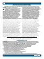
Power Off Alarm
You can choose whether to connect the power failure warning device to the
connecting terminal marked “Fault” according to your requirements. When using
power redundancy, if one power source fails, a fault alarm will be generated.
Chassis Ground Column
Located on the side of the power supply connector, a grounding terminal connector is used
to provide proper grounding for your Intellinet Network Solutions switch. If you use the
chassis grounding screw, it should be wired to an object that provides earth ground.
Placement
Desktop Installation
Prior to use, place/position the switch:
• on a level surface that can support the weight of the switch and that offers
at least 25 mm (approx. 1”) of clearance for ventilation;
• away from sources of electrical noise: radios, transmitters, broadband amplifiers;
• within 100 m (approx. 328’) of network devices it’s to be connected to.
DIN-Rail Installation
1 With DIN-rail bracket attached to device with screws, angle bracket onto DIN rail.
2 Push device in till it clicks into place.
Basic Web-Based Browser Management
1 Open your Web browser.
2 Enter http:// and the IP address of the switch in the Address field.
The default management IP address is 192.168.2.1.
3 Press Enter to display the login screen. In the Username field, enter admin; in the
Password field, enter the serial number on the bottom of the switch. Click OK.
1 2
The Intellinet 8-Port Gigabit Ethernet Layer 2+ Web-Managed Industrial Switch with 2 SFP Ports offers
an array of time-saving, cost-effective features while providing superior network throughput.
Features
• Provides RJ45 data connections for up to eight network devices
• IP30 slim-type metal housing to withstand harsh industrial conditions
• Wide operating temperature: -40 – 85°C (-40 – 185°F)
• Option for DIN-rail installation
• Two small form-factor pluggable GBIC module slots (SFP)
• Two redundant DC inputs (44 – 57 V) with I/O terminal block
With a backplane speed of 20 Gbps, plenty of performance is available for your computers, servers
and other networking devices. Each of the ports automatically senses the link speed of the connected
network device and adjusts to 10, 100 or 1000 Mbps for compatibility and maximum performance.
For the user manual and specifications, visit intellinetnetwork.com. Register your product
at register.intellinet-network.com/r/508834 or scan the QR code on the cover.
LEDs
LED Color Status Status Description
PWR Green On Power on
Off Power off; abnormal power
PWR1 &
PWR 2 Green On PWR input has power
Off Power is off or is working abnormally
Link/ACT
1 – 8
Green
(10/100 Mbps)
On Valid port connection (10/100 Mbps)
Blinking Sending or receiving data
Off No link established or port is connected at 1000 Mbps speed
Speed Green
(1000 Mbps)
On Valid port connection (1000 Mbps)
Off No link established or port is connected at 10/100 Mbps speed
SFP
1 & 2 Green
On Valid port connection
Blinking Sending or receiving data
Off No link established
Cat5e/6/6a UTP/STP cables provide optimal performance; if a status LED doesn’t indicate
a link or activity, check the corresponding device for proper setup and operation.
Power
Terminal Block Installation
NOTE: Ensure all power is off/disconnected before beginning!
1 Loosen appropriate screws.
2 Insert bare power-supply wires into appropriate terminal slots (positive
wire into positive slot; negative wire into negative slot).
3 Tighten appropriate screws to secure wires. (If desired, repeat steps 1 – 3 on second input pair.)
4 Install block into the device and tighten screws.
1
PWR 1 PWR 2 Fault
+
–
+
–
2
PWR 1 PWR 2 Fault
+
–
+
–
3
PWR 1 PWR 2 Fault
+
–
+
–
4
Instructions
English

4
Der Intellinet 8-Port Gigabit Ethernet Web-Managed Industrie-Switch mit 2 SFP-Ports bietet eine Reihe
von zeitsparenden, kosteneffektiven Funktionen und gleichzeitig einen hohen Netzwerkdurchsatz.
Merkmale
• RJ45-Datenverbindung für bis zu acht Netzwerkgeräte
• Schlankes Metallgehäuse mit Schutzklasse IP30 für anspruchsvolle Industrieumgebungen
• Für Umgebungstemperaturen von -40 bis 85°C
• Auf DIN-Schiene montierbar
• Zwei GBIC-Modul-Steckplätze (SFP)
• Redundante Stromversorgung mit zwei Eingängen (44 – 57 V) und I/O-Klemmleiste
Mit einer Backplane-Geschwindigkeit von 20 Gbps steht viel Leistung für Ihre Computer,
Server und andere Netzwerkgeräte zur Verfügung. Jeder der Ports erkennt automatisch die
Verbindungsgeschwindigkeit des angeschlossenen Netzwerkgeräts und stellt sich auf 10, 100
oder 1000 Mbit/s ein, um Kompatibilität und maximale Leistung zu gewährleisten.
Das Benutzerhandbuch und die technischen Daten finden Sie unter intellinetnetwork.com. Registrieren Sie Ihr
Produkt auf register.intellinet-network.com/r/508834 oder scannen Sie den QR-Code auf dem Deckblatt.
LED
LED Farbe Status Bedeutung
PWR
(Strom) Grün An Gerät wird mit Strom versorgt
Aus Ausgeschaltet; anormale Leistung
PWR1 &
PWR 2 Grün An PWR-Eingang hat Strom
Aus Das Gerät ist ausgeschaltet oder funktioniert nicht ordnungsgemäß
Link/
ACT
1 – 8
Grün
(10/100
Mbps)
An Verbindung ist hergestellt (10/100 Mbps)
Blinkend Senden oder Empfangen von Daten
Aus
Keine Verbindung hergestellt oder Port ist mit einer Geschwindigkeit von 1000 Mbit/s verbunden
Speed Grün (1000
Mbps)
An Verbindung ist hergestellt (1000 Mbps)
Aus
Keine Verbindung hergestellt oder Port ist mit einer Geschwindigkeit von 10/100 Mbit/s verbunden
SFP
1 & 2 Grün
An Verbindung ist hergestellt
Blinkend Senden oder Empfangen von Daten
Aus Verbindung ist nicht hergestellt
Cat5e/6/6a- UTP/STP-Kabel bieten die beste Performance. Wenn eine LED keine
Verbindung/Aktivität anzeigt, überprüfen Sie das verbundene Gerät.
Strom
Installation der Klemmleiste
HINWEIS: Vergewissern Sie sich, dass die Stromversorgung vor Beginn abgeschaltet/getrennt ist!
1 Lösen Sie die entsprechenden Schrauben.
2 Führen Sie die freiliegenden Stromkabel in die entsprechenden Steckplätze ein
(Pluskabel in den Plus-Steckplatz; Minuskabel in den Minus-Steckplatz).
3 Ziehen Sie die entsprechenden Schrauben an, um die Kabel zu fixieren. (Falls
Deutsch
Anleitung

5
gewünscht, wiederholen Sie die Schritte 1 - 3 am zweiten Eingangspaar.)
4 Setzen Sie die Leiste in das Gerät ein und ziehen Sie die Schrauben fest.
Strom-Aus-Fehlerwarnung
Sie können wählen, ob Sie die Netzausfallwarneinrichtung an die mit „Fault (Störung)“
gekennzeichnete Anschlussklemme anschließen. Bei Verwendung von Stromredundanz
wird bei Ausfall einer Stromquelle eine Fehlerwarnung generiert.
Gehäuseerdungsschraube
Der Erdungsendverbinder, der sich auf der rechten Seite des Netzsteckers befindet,
erleichtert die korrekte Erdung des Intellinet Network Solutions Schalters. Wenn Sie die
Gehäuseerdungsschraube verwenden, stellen Sie bitte sicher, dass sie mit einem Objekt
verbunden ist, das eine direkte Verbindung zu einem Erdungsleiter besitzt.
Nutzungsumgebung
Desktop-Installation
Er wird empfohlen, den Switch vor der Nutzung folgendermaßen:
• auf ebenem Untergrund, der das Gewicht des Switches
• auf ebenem Untergrund mit mind. 25 mm Rundumabstand für ausreichend Luftdurchsatz
• fern von anderen Übertragungsgeräten wie Radio, Breitbandverstärker, etc.
• max. 100 m vom zu verbindenden Netzwerkgerät entfernt.
DIN-Schienenmontage
1 DIN-Schienenhalterung mit Schrauben am Gerät befestigen, Winkelhalterung auf DIN-Schiene.
2 Schieben Sie das Gerät ein, bis es einrastet.
Grundlagen der Steuerung über den Webbrowser
1 Öffnen Sie Ihren Webbrowser.
2 Geben Sie http:// und die IP-Adresse des Switches in der Adresszeile
ein. Die Standard-IP-Adresse lautet 192.168.2.1.
3 Drücken Sie Enter, um zum Loginfenster zu gelangen. Geben Sie als Benutzernamen
admin. Geben Sie im Passwort-Feld die Seriennummer ein, die sich auf dem
Aufkleber auf der Unterseite des Switch befindet. Klicken Sie auf OK.
1
PWR 1 PWR 2 Fault
+
–
+
–
2
PWR 1 PWR 2 Fault
+
–
+
–
3
PWR 1 PWR 2 Fault
+
–
+
–
4
Anleitung
Deutsch
1 2

6
El Intellinet Switch industrial con 8 puertos Gigabit Ethernet administrado por
Web con 2 puertos SFP cuenta con múltiples características que le ahorrarán
tiempo y dinero, mientras disfruta de un mayor rendimiento en la red.
Caracteristicas
• Proporciona conexión de datos RJ45 para ocho dispositivos de red
• Carcasa metálica delgada IP30 para soportar las duras condiciones industriales
• Temperatura de funcionamiento amplia: -40 – 85°C
• Opción para instalación en carril DIN
• Dos ranuras de conexión para modulos miniGBIC (SFP)
• Dos entradas de CC redundantes (44 – 57 V) con bloque de terminales de E/S
Con una velocidad backplane de 20 Gbps, sus ordenadores, servidores y otros dispositivos de red podrán
disfrutar de un mayor rendimiento. Cada uno de los puertos detecta automáticamente la velocidad de
enlace del dispositivo y la ajusta a 10, 100 o 1000 Mbps para una compatibilidad y rendimiento máximos.
Para tener el manual de usuario y los requisitos, visita intellinetnetwork.com. Registre el producto
en register.intellinet-network.com/r/508834 o escanee el código QR en la cubierta.
LED
LED Color Estado Indicación
PWR Verde Encendido Encendido
Apagado Interruptor apagado; electricidad anormal
PWR1 &
PWR 2 Verde Encendido La entrada PWR tiene electricidad
Apagado La electricidad está ausente o funcionando de manera anormal
Link/
ACT
1 – 8
Verde
(10/100
Mbps)
Encendido Valide el puerto de conexión (10/100 Mbps)
Parpadeo Datos trasmitidos/recibidos
Apagado No se estableció conexión o el puerto está conectado a una velocidad de 1000 Mbps
Speed Verde
(1000 Mbps)
Encendido Valide el puerto de conexión (1000 Mbps)
Apagado No se estableció conexión o el puerto está conectado a una velocidad de 10/100 Mbps
SFP
1 & 2 Verde
Encendido Valide el puerto de conexión
Parpadeo Datos trasmitidos/recibidos
Apagado No hay comunicación
Los cables Cat5e/6/6a UTP/STP proporcionan un redimiento optimo; Si un LED no
indica conectividad ó actividad, compruebe las conexiones sean adecuadas.
Alimentación
Instalación del bloque de terminales
NOTA: asegúrese de que toda fuente de energía esté apagada/desconectada antes de comenzar.
1 Afloje los tornillos correspondientes.
2 Introduzca los cables de alimentación pelados en los orificios de los terminales adecuados
(cable positivo en orificio positivo, cable negativo en orificio negativo).
3 Apriete los tornillos correspondientes para asegurar los cables (si lo
desea, repita los pasos 1 a 3 en el segundo par de entrada).
Español
Instrucciones

7
4 Instale el bloque en el dispositivo y apriete los tornillos.
Alarma de falla eléctrica
Ud. puede optar por conectar a la terminal de conexión marcada como “Fault” [falla] el
dispositivo de alarma de aviso ante una falla eléctrica, según lo requiera. Al utilizar un sistema
de redundancia energética, si una de las fuentes de energía falla, se disparará una alarma.
Chasis-Tornillo de toma de tierra
Ubicado en el lado derecho del conector de la fuente de alimentación, el conector del
terminal de tierra facilita la adecuada conexión para el switch (conmutador) de Intellinet
Network Solutions. Cuando utilice el tornillo de toma de tierra del chasis, asegúrese de
engancharlo a un objeto que proporcione acceso directo a un conductor de tierra.
Colocación
Instalación de escritorio
Antes de utilizarlo, se recomienda que el switch sea colocado/fijado:
• sobre una superficie plana que pueda soportar el peso del switch (y
cualquier otro artículo que deba ser considerado);
• con un mínimo de 25 mm de espacio libre en la parte superior y en los lados para una ventilación adecuada;
• apartado de fuentes de ruido eléctrico: radios, transmisores, amplificadores, etc.;
• dentro de los 100 m (aprox. 328’) deben estar conectados los dispositivos de red.
Instalación del rail DIN
1 Para montar un soporte de rail DIN en el dispositivo mediante tornillos,
introduzca el soporte en el rail DIN formando un ángulo.
2 Empuje el dispositivo hacia adentro hasta que haga clic y quede fijo.
Administración básica vía Navegador Web
1 Inicie su Navegador Web.
2 Ingrese http:// y la dirección IP del switch en la barra de direcciones. La
dirección de administración por defecto es 192.168.2.1.
3 Presione Enter para ingresar a la pantalla de inicio de sesión. El nombre de usuario es admin, la contraseña
es el número de serie que está en la etiqueta en la parte inferior del conmutador. Haga clic en OK (Aceptar).
1
PWR 1 PWR 2 Fault
+
–
+
–
2
PWR 1 PWR 2 Fault
+
–
+
–
3
PWR 1 PWR 2 Fault
+
–
+
–
4
1 2
Español
Instrucciones

8
Instructions
L’Intellinet Commutateur industriel à gestion Web 8 ports couche 2+ Ethernet Gigabit
avec 2 ports SFP propose toute une gamme de fonctionnalités assurant le débit
optimal de votre réseau, ainsi qu’un gain notable de temps et d’argent.
Traits
• Muni de connexions de données RJ45 pour raccorder jusqu’à huit périphériques réseau
• Boîtier métallique IP30 à profil mince pour résister à des conditions industrielles extrêmes
• Écart de température pour le fonctionnement : -40 – 85 °C
• Option pour l’installation sur rail DIN
• 2 emplacements GBIC pour module émetteur/récepteur optique SFP
• Deux entrées redondantes en courant continu (44 – 57 V) avec bloc terminal I/O
Avec sa vitesse de fond de panier de 20 Gpbs, le commutateur offre des performances de
pointe à vos ordinateurs, à vos serveurs, et à vos autres appareils connectés. Chacun des ports
détecte automatiquement la vitesse de connexion de l’appareil réseau connecté, et s’ajuste
automatiquement à 10, 100 ou 1000 Mbps, pour une performance et une compatibilité accrues.
Pour obtenir le manuel utilisateur et des spécifications, visitez intellinetnetwork.com. Enregistrez votre
produit sur register.intellinet-network.com/r/508834 ou scannez le code QR figurant sur la couverture.
DEL
DEL Couleur Statut Indication
PWR Vert Allumé Appareil est alimenté
Éteint Éteindre ; puissance anormale
PWR1 &
PWR 2 Vert Allumé L’entrée PWR est alimentée
Éteint L’alimentation est coupée ou fonctionne anormalement
Link/
ACT
1 – 8
Vert
(10/100
Mbps)
Allumé Connexion est établie (10/100 Mbps)
Clignotant En train d’émettre ou de recevoir des données
Éteint Aucune liaison établie ou le port est connecté à une vitesse de 1000 Mbps
Speed Vert
(1000 Mbps)
Allumé Connexion est établie (1000 Mbps)
Éteint Aucune liaison établie ou le port est connecté à une vitesse de 10/100 Mbps
SFP
1 & 2 Vert
Allumé Connexion est établie
Clignotant En train d’émettre ou de recevoir des données
Éteint Connexion n’est pas établie
Des câbles Cat5e/6/6a UTP/STP garantissent des performances optimales; si
un DEL n’indique pas d’activité, vérifiez l’appareil correspondant.
Alimentation
Installation via bloc terminal
NOTE : Assurez-vous que l’alimentation est intégralement éteinte/déconnectée avant de commencer !
1 Desserrez les vis appropriées.
2 Insérez les fils d’alimentation nus dans les emplacements du terminal appropriés (fil
positif dans l’emplacement positif ; fil négatif dans l’emplacement négatif).
Français

9
Instructions
3 Serrez les vis appropriées pour fixer les fils. (Si vous le souhaitez,
répétez les étapes 1 à 3 sur la deuxième paire d’entrées.)
4 Installez le bloc dans le périphérique et serrez les vis.
Alarme de mise hors tension
Vous pouvez choisir de connecter ou non le dispositif d’avertissement de panne de courant à la borne
de connexion marquée «Fault» en fonction de vos besoins. Lors de l’utilisation de la redondance
d’alimentation, si une source d’alimentation tombe en panne, une alarme de panne sera générée.
Vis de châssis/Mise à la terre
Situé sur le côté droit du connecteur d’alimentation, le connecteur de terre facilite la mise à la terre
du commutateur de données Intellinet Network Solutions. Lors de l’utilisation de la vis de mise à la
terre du châssis, assurez-vous de la connecter à un objet qui fournit un accès direct à la terre.
Placement
Installation en bureau
Avant d’utiliser le commutateur, il est recommandé:
• de le placer sur une surface plane qui peut supporter son poids (et celui d’autres objets) ;
• ac. un écartement minimal de 25 mm d’autres objets pour une ventilation suffisante ;
• loin des appareils électriques qui peuvent être source d‘interférence (des radios etc.) ;
• pas plus loin que 100 m de l’appareil réseau auquel vous voudriez connecter.
Installation du DIN-Rail
1 Avec le support DIN-rail fixé au dispositif à vis, alignez le support avec le rail DIN.
2 Poussez le périphérique jusqu’à ce qu’il soit en place.
Base de la gestion Web
1 Ouvrez votre navigateur Web.
2 Entrez http:// et l’adresse IP du commutateur dans le champ Adresse.
L’adresse IP par défaut degestion est 192.168.2.1.
3 Appuyez sur Entrée pour afficher la fenêtre connexion. Dans le champ nom utilisateur,
entrez admin ; dans le champ mot de passe, saisissez le numéro de série figurant
sur l’autocollant qui se trouve au bas de l’interrupteur. Cliquez sur OK.
1
PWR 1 PWR 2 Fault
+
–
+
–
2
PWR 1 PWR 2 Fault
+
–
+
–
3
PWR 1 PWR 2 Fault
+
–
+
–
4
1 2
Français

10 Polski
Instrukcje
8-portowy przemysłowy przełącznik Gigabit Ethernet warstwy 2+ z 2 portami SFP, zarządzalny Intellinet
zapewnia oszczędność czasu i pieniędzy, oferując jednocześnie maksymalną przepustowość sieci.
Funkcje
• Zapewnia przepływ danych RJ45 dla maksymalnie ośmiu urządzeń sieciowych
• Odporna na trudne warunki przemysłowe metalowa obudowa o stopniu ochrony IP30
• Szeroki zakres temperatury pracy: -40 – 85°C
• Możliwość instalacji na szynie DIN
• Wyposażony w dwa sloty (SFP) na moduły GBIC
• Dwa redundantne wejścia zasilania DC (44 – 57 V) z blokiem zaciskowym I/O
Obwody drukowane o przepustowości 20 Gbps oferują wysoką wydajność twoim
komputerom, serwerom i innym urządzeniom sieciowym. Każdy z portów automatycznie
wykrywa prędkość łącza podłączonego urządzenia i optymalnie dostosowuje ją w
przedziałach 10, 100 lub 1000 Mbps, uzyskując maksymalną wydajność.
Instrukcja obsługi i specyfikacja produktu dostępne na stronie intellinetnetwork.com. Zarejestruj produkt
na register.intellinet-network.com/r/508834 lub zeskanuj znajdujący się na pokrywie kod QR.
Dioda LED
Dioda LED Kolor Stan Znaczenie
PWR Zielony Wł. Urządzenie włączone
Wył. Zasilanie wyłączone; nieprawidłowe zasilanie
PWR1 &
PWR 2 Zielony Wł. Zasilanie obecne na wejściu PWR
Wył. Zasilanie jest wyłączone lub działa nieprawidłowo.
Link/ACT
1 – 8
Zielony
(10/100
Mbps)
Wł. Prawidłowe podłączenie portu (10/100 Mbps)
Miga Wysyła lub odbiera dane
Wył. Nie ustanowiono połączenia lub port jest podłączony z prędkością 1000 Mbps
Speed Zielony
(1000 Mbps)
Wł. Prawidłowe podłączenie portu (1000 Mbps)
Wył. Nie ustanowiono połączenia lub port jest podłączony z prędkością 10/100 Mbps
SFP
1 & 2 Zielony
Wł. Prawidłowe podłączenie portu
Miga Wysyła lub odbiera dane
Wył. Nie nawiązano połączenia
Kable Cat5e/6/6a/6 UTP/STP zapewniają optymalną wydajność; jeśli diody statusu nie sygnalizują linku lub
aktywności, sprawdź podłączone urządzenie pod kątem poprawności konfiguracji oraz jego zasilania.
Zasilanie
Montaż bloku zacisków
UWAGA: Przed rozpoczęciem działania należy upewnić się, że odłączono lub wyłączono całe zasilanie!
1 Poluzować odpowiednie śruby.
2 Odsłonięte żyły kablowe zasilające należy umieścić w odpowiednich szczelinach zaciskowych (żyła
o polaryzacji dodatniej w szczelinie dodatniej, żyła o polaryzacji ujemnej w szczelinie ujemnej).

11
Polski
Instrukcje
3 W celu zabezpieczenia przewodów należy dokręcić odpowiednie śruby. (W
razie potrzeby powtórzyć kroki od 1 do 3 na drugiej parze wejść).
4 Zamontować blok w urządzeniu i dokręcić śruby.
Alarm braku zasilania
W zależności od potrzeb można wybrać, czy urządzenie ostrzegające o awarii zasilania ma być podłączone
do zacisku połączeniowego oznaczonego jako „Fault” (Awaria). W przypadku korzystania z nadmiarowości
zasilania, jeśli jedno źródło zasilania ulegnie awarii, zostanie wygenerowany alarm o awarii.
Śrubka uziemienia obudowy
Ulokowany po prawej stronie gniazda zasilania, terminal uziemiający pozwala prawidłowo uziemić
przełącznik Intellinet Network Solutions. W przypadku użycia śrubki uziemienia obudowy upewnij się,
że przewód połączony jest z przedmiotem z bezpośrednim dostępem do przewodnika uziemienia.
Umiejscowienie
Instalacja pulpitu
Zaleca się, aby urządzenie:
• w trakcie użytkowania było umiejscowione na płaskiej powierzchni,
w miejscu odpowiednim do wagi urządzenia;
• dla zapewnienia dobrej wentylacji w odległości co najmniej 25 mm
obudowy urządzenia od podłoża, na którym się znajduje;
• z dala od źródeł zakłóceń elektrycznych: radia, nadajniki szerokopasmowe, itp.;
• w odległości do 100 m od innych urządzeń sieciowych, z którymi bezpośrednio jest połączony.
Montaż na szynie DIN
1 Wgiąć wspornik szyny DIN przymocowany śrubami do urządzenia do szyny DIN.
2 Wsuwać urządzenie, aż zatrzaśnie się na swoim miejscu.
Konfiguracja podstawowa
1 Otwórz przeglądarkę internetową.
2 Wpisz http:// oraz adres IP przełącznika w pasek adresu przeglądarki.
Domyślnym adresem IP urządzenia jest 192.168.2.1.
3 Wciśnij Enter, aby wyświetlić okno logowania. W pole nazwa użytkownika wpisz admin, w polu
Hasło wpisz numer seryjny znajdujący się na naklejce na spodzie switcha. Wciśnij OK.
1
PWR 1 PWR 2 Fault
+
–
+
–
2
PWR 1 PWR 2 Fault
+
–
+
–
3
PWR 1 PWR 2 Fault
+
–
+
–
4
1 2

12
L’ Intellinet Switch Industriale 8 Porte Gigabit Layer 2 + 2 porte SFP Web- Managed offre una combinazione
di caratteristiche veloci e convenienti, pur fornendo una capacità di trasmissione eccellente.
Caratteristiche
• Fornisce connessione dati RJ45 per un massimo di otto dispositivi di rete
• Alloggiamento in metallo compatto IP30 per resistere a condizioni industriali difficili
• Ampia gamma di temperatura d’esercizio: -40 – 85°C
• Installazione su guida DIN opzionale
• Due alloggiamenti per slot per moduli GBIC (SFP)
• Due ingressi DC ridondanti (44 – 57 V) con terminal block I/O
Con una velocità della scheda di collegamento di 20 Gbps, una performance incredibile
sarà possibile per i vostri computer, server o altri dispositivi per la rete. Ognuna delle
porte traccia automaticamente la velocità del dispositivo di rete connesso e la regola
a 10, 100 o 1000 Mbps per massimizzare compatibilità e performance.
Per il manuale di utilizzo e le specifiche, visita
intellinetnetwork.com. Registra il tuo prodotto su
register.intellinet-network.com/r/508834 o scansiona il codice QR presente sulla copertina.
LED
LED Colore Stato Indicazione
PWR Verde Acceso Acceso
Spento Spento; potenza anomala
PWR1 &
PWR 2 Verde Acceso Alimentazione all’ingresso PWR
Spento L’alimentazione è spenta o funziona in modo anomalo
Link/
ACT
1 – 8
Verde
(10/100
Mbps)
Acceso Porta di connessione valida (10/100 Mbps)
Lampeggiante Invio o ricezione dati
Spento Nessun collegamento stabilito o la porta è collegata alla velocità di 1000 Mbps
Speed Verde
(1000 Mbps)
Acceso Porta di connessione valida (1000 Mbps)
Spento Nessun collegamento stabilito o la porta è collegata alla velocità di 10/100 Mbps
SFP
1 & 2 Verde
Acceso Porta di connessione valida
Lampeggiante Invio o ricezione dati
Spento Nessuna connessione stabilita
I cavi Cat5e/6/6a/6 UTP/STP forniscono ottimali prestazioni; se il LED di stato non indica una connessione
o un’attività, verificare la corrispondente periferica per un corretto settaggio e funzionamento.
Alimentazione
Installazione morsettiera
NOTA: Prima di iniziare, assicurarsi che l’alimentazione sia staccata/disattivata!
1 Allentare le viti appropriate.
2 Inserire i cavi nudi di alimentazione negli appositi alloggiamenti dei morsetti (il cavo positivo
nell’alloggiamento del positivo; il cavo negativo nell’alloggiamento del negativo).
3 Serrare le viti appropriate per fissare i cavi. (Se necessario, ripetere
Italiano
Istruzioni

13
i punti da 1 a 3 sulla seconda coppia di ingresso).
4 Installare il blocco nel dispositivo e serrare le viti.
Allarme di spegnimento
È possibile scegliere se collegare il dispositivo di avviso di interruzione dell’alimentazione al terminale
di connessione contrassegnato da “Fault”, in base alle proprie esigenze. Quando si utilizza la ridondanza
dell’alimentazione, se una fonte di alimentazione si guasta, verrà generato un allarme di guasto.
Vite di messa a terra del telaio
Collocato sul lato destro del connettore di alimentazione elettrica, il connettore del
terminal di messa a terra facilita la corretta messa a terra dello switch dati Intellinet
Network Solutions. Quando si utilizza la vite di messa a terra del telaio occorre collegarla
con un cavo a una oggetto che fornisca accesso diretto a un conduttore di massa.
Posizionamento
Installazione desktop
Prima di utilizzare il prodotto:
• si consiglia di fare attenzione a dove viene collocato lo switch su una superficie piana che può
supportare il peso dello switch (o qualsiasi altro oggetto che deve essere tenuto in considerazione);
• con un minimo di 25 mm di spazio libero verso l’alto e lateralmente
per permettere un’adeguata ventilazione;
• lontano da sorgenti che possono provocare disturbi e interferenze elettro
magnetiche: radio, trasmettitori, amplificatori di banda, ecc.;
• entro 100 m dalle periferiche di rete a cui è stato connesso.
Installazione su guida DIN
1 Con staffa per guida DIN fissata al dispositivo mediante viti, staffa angolare su guida DIN.
2 Spingere il dispositivo fino a quando non scatta in posizione.
Gestione tramite browser
1 Aprire il vostro Web browser.
2 Inserire http:// e l’indirizzo IP dello switch nel campo riservato
all’indirizzo. L’indirizzo IP predefinito è 192.168.2.1.
3 Premere Invio per visualizzare la schermata di accesso. Nel campo Username, inserire admin; nel campo
Password, inserire il numero di serie che si trova nell’adesivo sul fondo dell’interruttore. Cliccare OK.
1
PWR 1 PWR 2 Fault
+
–
+
–
2
PWR 1 PWR 2 Fault
+
–
+
–
3
PWR 1 PWR 2 Fault
+
–
+
–
4
1 2
Istruzioni
Italiano

14
WASTE ELECTRICAL & ELECTRONIC EQUIPMENT
DISPOSAL OF ELECTRIC AND ELECTRONIC EQUIPMENT
(Applicable In The European Union And Other European Countries With Separate Collection Systems)
ENGLISH: This symbol on the product or its
packaging means that this product must not
be treated as unsorted household waste. In
accordance with EU Directive 2012/19/EU on
Waste Electrical and Electronic Equipment (WEEE),
this electrical product must be disposed of in
accordance with the user’s local regulations for
electrical or electronic waste. Please dispose of this
product by returning it to your local point of sale
or recycling pickup point in your municipality.
DEUTSCH: Dieses auf dem Produkt oder der
Verpackung angebrachte Symbol zeigt an, dass dieses
Produkt nicht mit dem Hausmüll entsorgtwerden
darf. In Übereinstimmung mit der Richtlinie
2012/19/EU des Europäischen Parlaments und
des Rates über Elektro- und Elektronik-Altgeräte
(WEEE) darf dieses Elektrogerät nicht im normalen
Hausmüll oder dem Gelben Sack entsorgt werden.
Wenn Sie dieses Produkt entsorgen möchten,
bringen Sie es bitte zur Verkaufsstelle zurück oder
zum Recycling-Sammelpunkt Ihrer Gemeinde.
ESPAÑOL: Este símbolo en el producto o su
embalaje indica que el producto no debe tratarse
como residuo doméstico. De conformidad con
la Directiva 2012/19/EU de la UE sobre residuos
de aparatos eléctricos y electrónicos (RAEE), este
producto eléctrico no puede desecharse se con el
resto de residuos no clasificados. Deshágase de este
producto devolviéndolo a su punto de venta o a un
punto de recolección municipal para su reciclaje.
FRANÇAIS: Ce symbole sur Ie produit ou son
emballage signifie que ce produit ne doit pas être
traité comme un déchet ménager. Conformément à la
Directive 2012/19/EU sur les déchets d’équipements
électriques et électroniques (DEEE), ce produit
électrique ne doit en aucun cas être mis au rebut
sous forme de déchet municipal non trié. Veuillez
vous débarrasser de ce produit en Ie renvoyant à
son point de vente ou au point de ramassage local
dans votre municipalité, à des fins de recyclage.
POLSKI: Jeśli na produkcie lub jego opakowaniu
umieszczono ten symbol, wówczas w czasie
utylizacji nie wolno wyrzucać tego produktu
wraz z odpadami komunalnymi. Zgodnie z
Dyrektywą Nr 2012/19/EU w sprawie zużytego
sprzętu elektrycznego i elektronicznego (WEEE),
niniejszego produktu elektrycznego nie wolno
usuwać jako nie posortowanego odpadu
komunalnego. Prosimy o usuniecie niniejszego
produktu poprzez jego zwrot do punktu zakupu
lub oddanie do miejscowego komunalnego punktu
zbiórki odpadów przeznaczonych do recyklingu.
ITALIANO: Questo simbolo sui prodotto o
sulla relativa confezione indica che il prodotto
non va trattato come un rifiuto domestico. In
ottemperanza alla Direttiva UE 2012/19/EU sui
rifiuti di apparecchiature elettriche ed elettroniche
(RAEE), questa prodotto elettrico non deve
essere smaltito come rifiuto municipale misto.
Si prega di smaltire il prodotto riportandolo al
punto vendita o al punto di raccolta municipale
locale per un opportuno riciclaggio.
WARRANTY INFORMATION • GARANTIEINFORMATIONEN •
GARANTÍA • GARANTIE • GWARANCJI • GARANZIA
intellinetnetwork.com
EN MÉXICO: Póliza de Garantía Intellinet — Datos del importador y responsable ante el consumidor IC
Intracom México, S.A.P.I. de C.V. • Av. Interceptor Poniente # 73, Col. Parque Industrial La Joya, Cuautitlán
Izcalli, Estado de México, C.P. 54730, México. • Tel. (55)1500-4500 • La presente garantía cubre los
siguientes productos contra cualquier defecto de fabricación en sus materiales y mano de obra.
A Garantizamos los productos de limpieza, aire comprimido y consumibles, por 60
dias a partir de la fecha de entrega, o por el tiempo en que se agote totalmente
su contenido por su propia función de uso, lo que suceda primero.
B Garantizamos los productos con partes móviles por 3 años.
C Garantizamos los demás productos por 5 años (productos sin
partes móviles), bajo las siguientes condiciones:
1 Todos los productos a que se refiere esta garantía, ampara su
cambio físico, sin ningún cargo para el consumidor.
2 El comercializador no tiene talleres de servicio, debido a que los productos que se garantizan

15
North America
IC Intracom America
550 Commerce Blvd.
Oldsmar, FL 34677, USA
Asia & Africa
IC Intracom Asia
4-F, No. 77, Sec. 1, Xintai 5th Rd.
Xizhi Dist., New Taipei City 221, Taiwan
Europe
IC Intracom Europe
Löhbacher Str. 7, D-58553
Halver, Germany
no cuentan con reparaciones, ni refacciones, ya que su garantía es de cambio físico.
3 La garantía cubre exclusivamente aquellas partes, equipos o sub-ensambles que
hayan sido instaladas de fábrica y no incluye en ningún caso el equipo adicional o
cualesquiera que hayan sido adicionados al mismo por el usuario o distribuidor.
Para hacer efectiva esta garantía bastará con presentar el producto al distribuidor en el domicilio
donde fue adquirido o en el domicilio de IC Intracom México, S.A.P.I. de C.V., junto con los accesorios
contenidos en su empaque, acompañado de su póliza debidamente llenada y sellada por la casa
vendedora (indispensable el sello y fecha de compra) donde lo adquirió, o bien, la factura o ticket de
compra original donde se mencione claramente el modelo, número de serie (cuando aplique) y fecha
de adquisición. Esta garantía no es válida en los siguientes casos: Si el producto se hubiese utilizado en
condiciones distintas a las normales; si el producto no ha sido operado conforme a los instructivos de
uso; o si el producto ha sido alterado o tratado de ser reparado por el consumidor o terceras personas.
REGULATORY STATEMENTS
FCC Class A
This equipment has been tested and found to comply with the limits for a Class A digital device, pursuant
to Part 15 of the Federal Communications Commission (FCC) Rules. These limits are designed to provide
reasonable protection against harmful interference when the equipment is operated in a commercial
environment. This equipment generates, uses and can radiate radio frequency energy, and if not installed and
used in accordance with the instruction manual may cause harmful interference to radio communications.
Operation of this equipment in a residential area is likely to cause harmful interference, in which case the
user will be required to correct the interference at his own expense. Any changes or modifications made
to this equipment without the approval of the manuafacturer could result in the product not meeting
the Class A limits, in which case the FCC could void the user’s authority to operate the equipment.
CE
ENGLISH: This device complies with the requirements of CE 2014/30/EU and / or
2014/35/EU. The Declaration of Conformity for is available at:
DEUTSCH: Dieses Gerät enspricht der CE 2014/30/EU und / oder 2014/35/EU. Die
Konformitätserklärung für dieses Produkt finden Sie unter:
ESPAÑOL: Este dispositivo cumple con los requerimientos de CE 2014/30/EU y / o
2014/35/EU. La declaración de conformidad esta disponible en:
FRANÇAIS: Cet appareil satisfait aux exigences de CE 2014/30/EU et / ou
2014/35/EU. La Déclaration de Conformité est disponible à :
POLSKI: Urządzenie spełnia wymagania CE 2014/30/EU I / lub 2014/35/EU. Deklaracja
zgodności dostępna jest na stronie internetowej producenta:
ITALIANO: Questo dispositivo è conforme alla CE 2014/30/EU e / o 2014/35/EU.
La dichiarazione di conformità è disponibile al:
support.intellinet-network.com/barcode/508834
All trademarks and trade names are the property of their respective owners.
Alle Marken und Markennamen sind Eigentum Ihrer jeweiligen Inhaber.
Todas las marcas y nombres comerciales son propiedad de sus respectivos dueños.
Toutes les marques et noms commerciaux sont la propriété de leurs propriétaires respectifs.
Wszystkie znaki towarowe i nazwy handlowe należą do ich właścicieli.
Tutti i marchi registrati e le dominazioni commerciali sono di proprietà dei loro rispettivi proprietari.

-
 1
1
-
 2
2
-
 3
3
-
 4
4
-
 5
5
-
 6
6
-
 7
7
-
 8
8
-
 9
9
-
 10
10
-
 11
11
-
 12
12
-
 13
13
-
 14
14
-
 15
15
-
 16
16


Intellinet 508834 Quick Instruction Guide
- Typ
- Quick Instruction Guide
in anderen Sprachen
- English: Intellinet 508834
- français: Intellinet 508834
- español: Intellinet 508834
- italiano: Intellinet 508834
- polski: Intellinet 508834