
• E x II
• S c hutzart IP 66
• E xplosionsgesc hützter
optis c h/akus tis c her
S ignalgeber
•
ATE X-bes c heinigt nac h
R ichtlinie 94/9/EG
• Lauts tarker Mehrtonwec ker
• Leis tungs s tark e B litzleuc hte
• E x II
• P rotec tion c ategory IP 66
• E xplos ion- proof optic al
and ac ous tic
s ignalling devic e
• ATE X- c ertified ac c .
to direc tive 94/9/E C
• Loud multitone bell
• P owerful s trobe light
Verwendungs hinweis e
Der
ist speziell für die Ver-
wendung in e
xplosionsgefährdeten
Industriebereichen konstruiert und
erlaubt das Betreiben in Gebäuden
und im Freien. Über einen S chiebe-
schalter lässt sich der
in die folgenden Betriebsarten
schalten:
•
In dieser Betriebsart wird der
mit einem Telefon
(mit W-Ader-Anschluss) zu sam -
mengeschaltet, um ein weiteres
akustisches und opt i sches S ig-
nal entfernt vom Telefon zu
erzeugen. Das akustische S ignal
endet mit dem
R uf. Das opti-
sche Signal bleibt während der
Rufpausen bestehen (Rufpau-
senüberbrückung). Das op tische
S ignal endet ca. 4 s nach dem
letzten R uf.
Die Speisung der optischen und
akustischen S ignale erfolgt aus
dem 230 V Netz. Angesteuert
werden die Signale durch die
Rufwechselspannung. Bei Aus-
fall des Netzes erfolgt keine
S ignalisierung.
•
S ignalmelder
In dieser Betriebsart werden
durch das Anlegen des 230 V
Netzes die akustischen und
optischen S ignale erzeugt.
Montage
Der ist für die Wand-
und Deckenmontage geeignet.
Die Anbaumaße sind dem Maßbild
(siehe „Maßbild“) zu entnehmen.
Befestigungselemente und Unter-
grund müssen das Gewicht des
Gerätes (ca.1,5 kg) tragen können
.
Ans c hließen
Das Anschließen und Einstellen
des Gerätes darf nur durch unter-
wiesenes Fachpersonal erfolgen.
Es sind die Vorschriften und Hin-
weise des jeweiligen Landes zum
1
Applic ation Notes
The
is
especially con-
ceived for use in industrial hazar-
dous areas, allowing operation in
industry buildings and outdoors.
The DIP switch of the
Ex II
can
be used to switch the
device
to the following operating
modes:
•
Additional Telephone S ignalling
Device
For this operating mode the
Ex II is connected with a
telephone (with a W conductor)
t
o generate a further acoustic
and optical signal away from the
telephone. The ringing ends the
acoustic signal. The optical sig-
nal remains during the ringing
pauses (ringing pause bridging).
The optical signal ends approx.
4 sec. after the last ring. The
optical and acoustic signals are
supplied from the 230 V line. The
ringing alternating current is
used for controlling the signals.
In case of a loss of line voltage
there will be no signalling.
•
S ignalling Device
In this mode the acoustic and
optical signals are generated
upon connection to the 230 V
line.
Mounting
The Ex II is suited for wall
and ceiling mounting. R efer to the
dimensional drawing for the moun-
ting dimensions (refer to figure
„Physical dimensions“). Both the
fasteners and the mounting surfa-
ce must be able to carry the weight
of the device (~1.5 kg).
C onnec ting
Only especially educated profes-
sional personnel may connect and
adjust the device. The rules and
regulations of each country regar-
ding connections to the public tele-
phone network or private branch
exchanges must be observed.
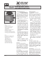
Anrufmelder optisch - akustisch
visual - audible secondary sounder
Typ VS1
Anrufmelder optisch - akustisch Ex II
Ex II
Anrufmelder optisch - akustisch Ex II
Ex II
Ex II
Ex II
visual - audible secondary sounder
VS1 3.0

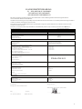
Technis che Daten
Typ:
Gerätebezeichnung:
ExII-
Lagertemperatur: -20°C ... +70°C
Betriebsumgebungstemperatur -20°C ... +40°C
Gebrauchslage: beliebig (Wand- und Deckenmontage)
In Räumen mit starker S taub und/oder Wassereinwirkung sollte die
S challtrichteröffnung nach unten zeigen.
Gehäuseschutzart: IP66
Zündschutzart:
I I
2G Ex mb e [ib] IIC T6
Zulassungen: PTB 04 ATEX 2012
Netzanschluss: L1, N, PE, PE am Gehäuse
230 V -15% +10% / 50 Hz / PE am Gehäuse
Vorzuschaltende S icherung: 500 mA bei 230 V Netz
800 mA bei 120 V Netz
Telefonnetz: W, Lb
30 V
AC
...75 V
AC
/ 23 Hz ... 54 Hz / 0 V
DC
... 63 V
DC
Akustische S ignalisierung: nur mit 230 V Netz
S ignalgeber: Lautsprecher
S ignale: Einzeltonruf / 2Tonruf / 3Tonruf
Lautstärke: ca. 90 dB(A) in 1m Abstand
Optische S ignalisierung: nur mit 230 V Netz
S ignalgeber: 2 Blitzröhren, W ca. 0,9 Ws
Blitzfrequenz: 1 H z ... 2 Hz
Anschlussklemmen: Klemmbereich bis 1,5 mm
2
ein- und feindrähtig
Kabeleinführung: 2x M20 x 1,5
Kabeldurchmesser: 6 – 12 mm (230 V Netz)
5 – 10 mm (Telefonnetz)
Gehäusematerialien: Gehäuse: Druckguss-Aluminium
Haube: Polycarbonat
Abmessungen: ca. 195 x 150 x 104 mm
Gewicht: ca. 1,5 kg
2
Anschalten an das öffentliche
Telefonnetz bzw. an private Neben-
stellenanlagen zu beachten.
Nachfolgende Anschluss- und Ein-
stellvorschriften sind einzuhalten:
Es sind die Vorschriften und Hin-
weise zum Anschalten an das
230 V Netz zu beachten.
•
Netzanschluss: Klemmen L1, N,
S chutzerde PE, zusätzlich PE
am Gehäuse
•
Telefonanschluss: Klemmen W,
Lb.
Wahl der B etriebs arten:
•
Telefonzweitmelder
Für das Netz sind die Klemmen
L1, N, PE auf der linken S eite im
Gerät vorgesehen. Für das Tele-
fonetz sind die Klemmen Lb, W
auf der rechten S eite im Gerät
vorgesehen. Der linke Kontakt
im S chiebeschalter muss in der
Po si tion „Telefonzweitmelder“
stehen (siehe „Einstellen des
S chiebeschalters“).
•
S ignalmelder
Für das Netz sind die Klemmen
L1, N, PE auf der linken S eite im
Gerät vorgesehen. Der linke
Kon takt im S chiebeschalter
muss in der Position „S ignalmel-
der“ stehen (siehe „Einstellen
des S chiebeschalters“).
Wahl der M elodie
Mit den anderen K
ontakten des
S chiebeschalters lässt sich die
Melodie des akustischen S ignales
veränder
n (siehe „Einstellen des
S chiebeschalters“).
Hinweis :
Vor Installation des
Ex II ist
die Gebrauchsanweisung sorgfältig
zu lesen. Bei eventuellen Schäden
und Ansprüchen gelten die „Allge-
meinen Lieferbedingungen für Er-
zeug nisse und Leistungen der
Elektroindustrie“ in ihrer jeweils
letzten Fassung.
R ec yc ling
Die Komplettentsor
gung der Geräte
erfolgt über den Elektronikabfall. B ei
Demontage des Gerätes sind die
Komponenten Kunststoff, Me talle
und Elektronik separat zu ent sorgen.
Das Gerät erfüllt die Anforderun-
gen der neuen EMV-R ichtlinie
2004/108/EG und der Nieder-
spannungs-Richtlinie 2006/95/EG.
Die Konformität mit den oben
genannten R ichtlinien wird durch
das CE-Zeichen bestätigt.
E M V- R i c h t l i n i e
VS1
Anrufmelder optisch-akustisch

The following regulations regarding
connection and adjustments must
be obeyed: The rules and regula-
tions of each country regarding
connections to the 230 V power
supply network must be observed.
•
Power supply to terminals L1, N,
PE. In addition: Protective Earth
to housing.
•
Telephone connection: Terminals
W, Lb
C hoic e of operating modes :
•
Additional Telephone S ignalling
Device
The terminals L1, N, PE on the
l
eft inner side of the device are
to be used for connecting to the
power supply. The terminals Lb,
W on the right inner side of the
device are to be used for con-
necting to the telephone net-
work. The left contact in the DIP
switch must be in the position
„Telephone S ignalling Device“
(refer to „Adjusting the DIP
switch“).
•
S ignalling Device
The terminals L1, N, PE on the
left inner side of the device are
to b
e used for connecting to the
power supply. The left contact in
the DIP switch must be in the
position „S ignalling Device“ (refer
to „Adjusting the DIP switch“).
C hoic e of melody
The other contacts of the DIP
switch may be used to change the
melody of the acoustic signal (refer
to „Adjusting the DIP switch“).
Note:
Prior to installing the ExII,
the operating instructions must be
read carefully. In case of any d
ama-
ge and liabilities the latest version
of the „General terms of delivery of
products and services in the elec-
tric industry“ is authoritative.
R ec yc ling
The devices may be completely
recycled as electronic waste.
Upon disassembling the devices,
the plastic, metal and electronics
components must be disposed of
separately.
Technic al s pec ific ation
Type:
Device designation:
S torage temperature: -20°C to +70°C
Ambient operation temperature: -20°C to +40°C
Operation position: any (wall mount, ceiling mount)
If possible, avoid ceiling mounting in rooms considerably
influenced by dust or water
Protection category: IP66
Explosion category:
I I
2G Ex mb e [ib] IIC T6
Approvals: PTB 04 ATEX 2012
Power connection: L1, N, PE, PE at housing
230 V -15% +10% / 50 Hz / PE at housing
Preconnecting overcurrent 500 mA by 230 V line voltage
protector: 800 mA by 120 V line voltage
Telephone connection: W, Lb
30 V
AC
... 75 V
AC
/ 23 Hz ... 54 Hz / 0 V
DC
... 63 V
DC
Acoustic signalling: only with 230 V line voltage
S ignalling device: Loudspeaker
S ignals: single tone / 2-tone call/ 3-tone call
S ound pressure level: approx. 90 dB (A) at 1m
Optical signalling: only with 230 V line voltage
S ignalling device: 2 flash tubes, W approx. 0.9 Ws
Flash frequency: 1 Hz...2 Hz
Terminals: max. cable cross section 1.5 mm
2
single core, fine strand
Cable entry: 2x M20 x 1.5
Cable diameters: 6 – 12 mm ( 230 V line voltage )
5 – 10 mm ( telephone line )
Housing material: Die-casting aluminium
Hood: Polycarbonate
Physical dimensions: approx. 195 x 150 x 104 mm
Weight: approx. 1.5 kg
3
The device complies with the
requirements of the new EMC -
directive 2004/108/EC and the low
voltage directive 2006/95/EC .
The conformity with the above
directives is confirmed by the CE
sign.
E M C - D i r e c t i v e
VS1
Ex II visuel-audible secondary sounder

4
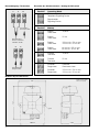
Einstellen des Schiebeschalters / Setting the DIP switch
Maßbild / Physical dimensions
Netzspannung /
Power connection
230 VAC / 50 Hz
Schutzerde /
Protective earth
Telefonleitung /
Telephone line
W Lb
L1 N PE
~ 104
~ 150
ø 5,5
~ 195
130±0,5
Klemmbelegung / Termination
Stellung Betriebsart
Position Operating Mode
Stellung Melodie
Position Melody
Telefonzweitmelder
Telephone Signalling Device
Signalmelder
Signalling Device
Dreiton
16,6 Hz
Three-tone
Dreiton
50 Hz
Three-tone
Dreiton 120 ms ein / 50 ms aus
Three-tone 120 ms on / 50 ms off
Dreiton 60 ms ein / 25 ms aus
Three-tone 60 ms on / 25 ms off
Zweiton
16,6 Hz
Two-tone
Zweiton
50 Hz
Two-tone
Einzelton Dauerton
Single-tone Continuous tone
Einzelton 120 ms ein / 50 ms aus
Single-tone 120 ms on / 50 ms off
Abmessungen [mm]
Dimensions [mm]

5
EG KONFORMITÄTSERKLÄRUNG
EC – DECLARATION OF CONFORMITY
DECLARTION CE DE CONFORMITE
DELLARCION DE CONFORMIDAD CE
Wir erklären in alleiniger Verantwortung, dass das Produkt auf das sich diese Erklärung bezieht mit der/den folgenden Normen
oder normativen D okumenten übereinstimmt:
Herewith we declare bearing sole responsibility that the product referred in this declaration is in conformity with the following standards or
normative documents and regulations of the directive:
Nous declarons de notre seule responsabilite que le produit auquel se rapporte la presnte declaration est conforme aux normes ou aux
documents normatifs suivants :
Declaramos, con nuestra exclusiva responsabilidad, la conformidad del producto al que se reere la presente declaracion la(s) norms(s)
Bezeichnung des Erzeugnisses
Optisch -Akustischer Signalmelder
Name of product Visual -Audible Signalling Sounder
Titre Produit Amplicateur optique et sonore
Nombre del producto Indicador acústico -luminoso
Geräte - oder Typenbezeichnung
Equipment type or mark of equipment
Identication du produit
VS1
Nombre del aparato o del tipo
Bestimmung der Richtlinie
Nr. und Ausgabedatum der Norm(en)
Provisions of t he directive No. and date of issue of the standard(s)
Désignation de la directive No. et date d´ émision de la/des norme(s)
Directiva aplicable N° y fecha de emisión de la(s) norma(s)
94/9/EG: Geräte und Schutzsyteme zur bestimmungsgemäßen
Verwendung in explosionsge fährdeten Bereichen
EN 60079-0:2006
94/9/EC: Equipment and protective system intended for use in EN 60079-7:2007
potentially explosive atmospheres EN 60079-11:2007
94/9/CE: Appareils et systéme de protection desti nés á étre EN 60079-18:2004
utilisés en atmosphéres explosibles
94/9/CE : aparatos y sistemas de proteccón para uso en
atmósferas potenciaömente explosivas
EG Baumusterprüfbescheinigung
EC -
type -
examination certicat e
PTB 03 ATEX 2012
Attestation examen CE
Certicado de examen CE
Benannte Stelle für die Bescheinigung
PTB, D -38116 Braunschweig
Notied body of the certicate
Organisme notié de l` attestation
Organismo encargodo del certicado
Be nannte Stelle für die Überwachung
TÜV -Österreich
Notied body of the inspection TÜV -A
Organisme notié de contróle Krugerstraße 16
Organismo encargodo del examen A-1015 Wien
Kennummer
Inspection number / Numéro d`iden tication 0408
Número de examen
Hersteller / Anschrift
J.Auer GmbH
Manufacturer / Factory address Perfektastr. 102
Fabricant / Adresse A-1230 Wien
Geschäftsfrührer:
Dipl. Ing. Michael Auer
Managing director / Direction Gérant / Gerente: .......................................................
(Name, Vorname / name, prename / apellido, nombre)
Wien 20.09.2010
...................................... ............................. ...... .......................................................
(
Ort
/ place / lieu / población) (
Datum
/ date / fecha )
(Rechtgültige Unterschrift)

Änderungen und Irrtum vorbehalten
S ubject to alterations or errors
Bei diesem B etriebsmittel handelt es sich um ein
explosionsgeschützt ausgeführtes Gerät für den
Betrieb innerhalb explosionsgefährdeter Bereiche
der Gruppe II (Zone 1 und Zone 2 ).
Nachstehende Warn- und Sicherheitshinweise
sind zu beachten:
1. Das Gerät ist in S chutzklasse I aufgebaut und
darf nur an der vorgeschriebenen Spannung
an geschlossen und betrieben werden. Es ist
auf einen ordnungsgemäßen Ansch
luss zu
achten.
2. Das Gerät darf nur unter den angegebenen
Umgebungsbedingungen betrieben werden
(siehe technische Daten). Widrige Umge-
bungsbedingungen, wie z.B . zu hohe oder zu
niedrige Umgebungstemperaturen, sind nicht
zulässig.
3. Das Gerät verfügt über eine hohe Leuchtstär-
ke. B ei direktem B lickkontakt zum B litzzeit-
punkt in das optische Signal kann eine kurz-
zeitige B ehinderung des S ehvermögens ein
-
treten.
4. Die in den technischen Daten aufgeführten
Angaben sind einzuhalten.
5. Bei dem Betrieb des Gerätes sind die gesetz-
lichen und gewerblichen Vorschriften, Unfall-
verhütungsvorschriften sowie elektrische Be -
stimmungen zu beachten.
6. Es ist darauf zu achten, dass das Gerät nicht
beschädigt wird. Im beschädigten Zustand ist
das Betreiben des Gerätes nicht zulässig.
7. Bei R eparaturen sind nur Origi
nalersatzteile
zulässig. Andere Austauschteile können zu
S ach- und Personenschäden führen.
8. Das Gerät darf nur von einer unterwiesenen
Fachkraft geöffnet und instandgesetzt werden.
9. Es ist verboten, in dem Gerät zusätzliche
Leitungsverbindungen herzustellen.
10. Innerhalb der vorgeschalteten, elektrischen
Versorgungseinrichtungen muss ein Kurz-
schlussschutz vorhanden sein, dessen
Begrenzung auf maximal 5
00 mA ausgelegt
sein muss (siehe dazu die PTB-Bescheinigung).
11. Änderungen des Produktes, die dem techni-
schem Fortschritt dienen, sind jederzeit mög-
lich.
The equipment described in this Operating
instructions manual is an explosion proof device
for use in hazardous areas of Group II and Zones
1 and 2.
The following warnings and safety notes must be
especially observed:
1. The device is designed in compliance with
insulation class I and may be connected and
operated at the mandatory voltage only.
A proper connection must be especially
observed.
2. The device ma
y be operated under the man-
datory ambient conditions only (refer to Tech-
nical speci fications ). B ad ambient conditions,
for instance too low or too high ambient tem-
peratures, are not permitted.
3. The device features a high luminous intensity.
Direct exposure of the eyes to the optical
signal at the moment of the flash may cause a
temporary reduction of the seeing ability.
4. The information given in
the Technical data
must be observed.
5. During operation of the device the legal and
professional regulations, the safety regula-
tions, and the electrical rules and regulations
must be observed.
6. Make sure the device is undamaged. If the
device is damaged it may not be operated.
7. In case of repairs only original spare parts
may be used. Any other spare parts may lead
to personal injury and/or equipment d
amage.
8. The device may be opened and repaired by
educated professional personnel only.
9. It is prohibited to make additional electrical
connections to the device.
10. Within the feeding mains supply circuit, a
short circuit protection must be installed,
which limits the rated current to a maximum
of 500 mA (refer also to PTB certificate).
11. This product may be subject to modifications
serving technical pro
gress without further
notice.
B enutzerinformation Us er information
J. Auer Fabrik Elektrischer Maschinen Gesellschaft m. b. H
Perfektastr. 102 Phone (00431) 813 82 20 http://www.auer-signal.com
A-1230 Wien Telefax (00431) 815 99 51 e-mail: o[email protected]
-
 1
1
-
 2
2
-
 3
3
-
 4
4
-
 5
5
-
 6
6


in anderen Sprachen
- English: auer Ex II VS1 User manual
Verwandte Papiere


Sonstige Unterlagen
-
FHF 5842/2 Benutzerhandbuch
-
-
 werma 761 000 67 Instructions For Use Manual
-
Eaton DB3B Technical Manual
-
Cooper GHG 635 Operating Instructions Manual
-
Eaton Crouse-hinds series Operating Instructions Manual
-
Eaton GHG 273 Operating Instructions Manual
-
