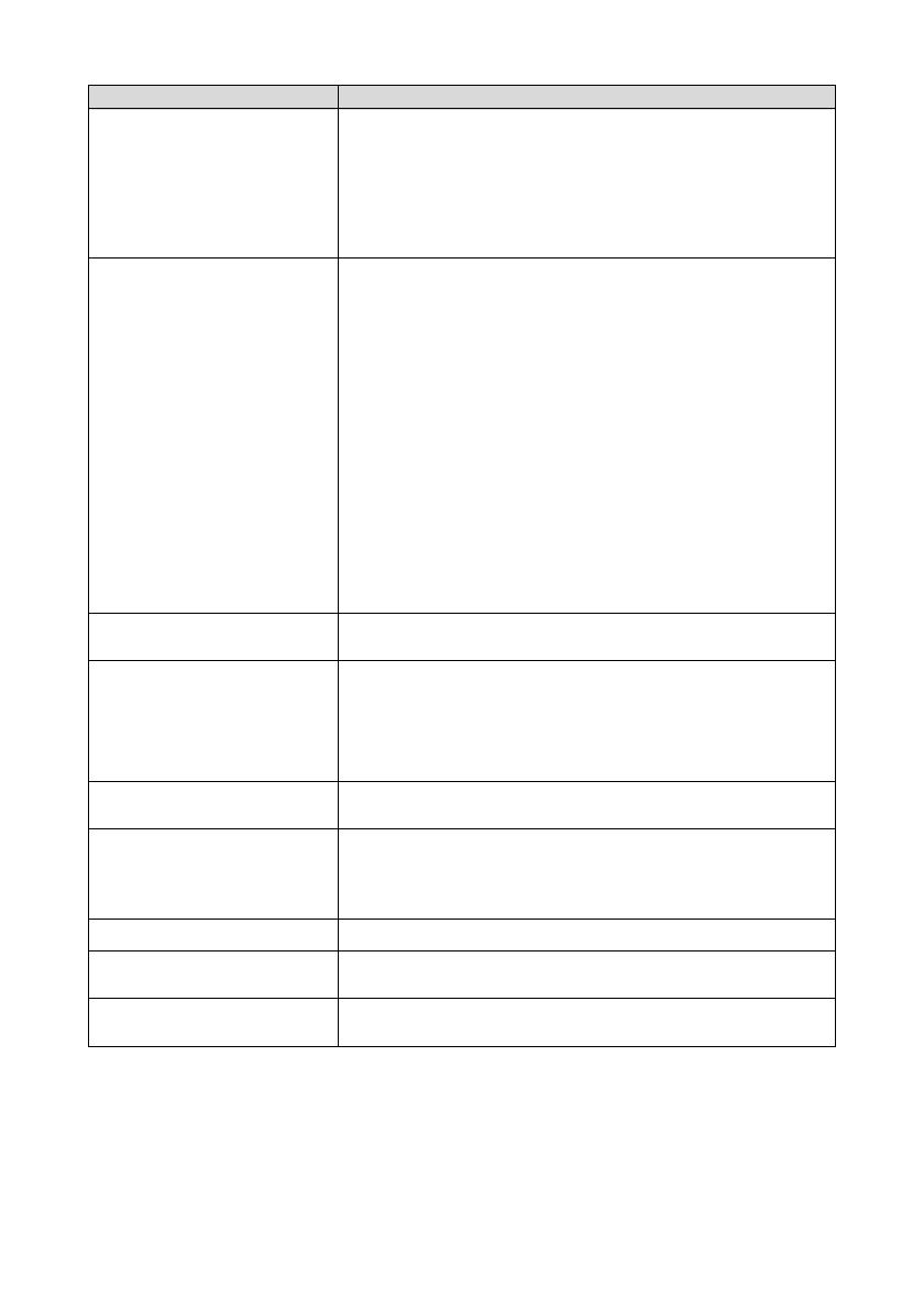
NEC WT600 Bedienungsanleitung

Kategorie
Projektoren
Typ
Bedienungsanleitung
[English]
WT600 SETUP GUIDE
[Deutsch]
AUFSTELLUNGSANLEITUNG WT600
[Français]
WT600 - GUIDE D’INSTALLATION
[Italiano]
GUIDA DI IMPOSTAZIONE WT600
[Español]
GUÍA DE INSTALACIÓN DE LA UNIDAD WT600
[Svenska]
WT600 INSTALLATIONSGUIDE
WT600 SETUP GUIDE
Contents
Screens Suited for the WT600 ........................................... E-2
Stands Suited for the WT600 ............................................. E-2
Ambient environmental condition ....................................... E-3
Part Names of the Projector ............................................... E-3
1. Setting Up the Screen and Projector .............................. E-4
2. Connections ................................................................... E-5
3. Opening the Mirror ......................................................... E-5
4. Switchng on the Power ................................................... E-6
5. Selecting Signals ............................................................ E-6
6. Adjusting the Position and Size of the Projected Image
(Focus Adjustments) ....................................................... E-7
7. Adjusting Pincushion or Barrel Distortion
(Pincushion) .................................................................. E-11
8. Troubleshooting ............................................................ E-13
P
O
W
E
R
E
N
T
E
R
M
E
N
U
S
O
U
R
C
E
F
O
C
U
S
P
C
C
A
R
D
C
A
N
C
E
L
S
T
A
TU
S
L
A
M
P
O
N
/
S
T
A
N
D
B
Y
A
U
TO
A
D
JU
S
T
3
D
R
E
F
O
R
M
S
E
LE
C
T
PC C
AR
D
A
U
D
IO
IN
R
L
/M
O
N
O
VIDEO IN
S-V
IDEO
IN
DV
I-I IN
R
GB
IN RGB OUT
DV
I-I
RGB
AUDIO IN
USB
AUD
IO OUT
P
C
CON
TROL
REM
OTE
IN
NOTE
(1) The contents of this guide may not be reprinted in part or whole without permission.
(2) The contents of this guide are subject to change without notice.
(3) Great care has been taken in the creation of this guide; however, should any ques-
tionable points, errors, or omissions be apparent, please contact us.
(4) Notwithstanding Section (3), this company will not be responsible for any claims of
loss or profit or other matters deemed to be the result of using this unit.
(5) Guides with incorrect collating or missing pages will be replaced.
(6) When differences arise between this guide and the user's manual, this guide will be
given priority.
Scope of this Guide
The subject of this guide is to describe the procedure for adjusting the
image projected from the WT600 to the desired screen size. Descrip-
tions of screens and stands for use with the WT600 are also provided.
Please see the user's manual for information regarding the detailed
operation of the WT600 (hereafter referred to as "the unit" or "the pro-
jector").
E-1
WARNING
Do not set up the projector, the screen or stand in a place that is not level or in an
unstable location. Doing so may result in the screen falling over or the projector falling
which may result in injury.
When setting up the projector on the stand, first secure the top plate in a level condi-
tion. When the top plate is set at an angle, the projector may fall resulting in injury.
Use a stand that can fully support the weight of the projector (which for this unit is
approximately 13lbs/5.9 kg). Failing to do so may result in the projector falling and
causing injury.
E-2
40"-100"
90˚
Screens Suited for the WT600
Screens with a soiled, scratched, or discolored area will not produce a clean
image. Care should be used in the handling of the screen.
Recommended
Not recommended
Recommended
Not recommended
Recommended
Not recommended
Not recommended
Not optimal
Not recommended
Not recommended
Use a panel or tension type screen that has a flat surface.
Do not use roll type screens and other screens that bend or
form a wavy surface easily. Doing so will result in increased
distortion of the projected image.
The unit can accommdate screen sizes from 40” (81.3 cm/32.0” W 61.0
cm/24.0” H) to 100 inch (203.2 cm/80.0” W 152.4 cm/60.0” H).
View the screen directly from the side so that it is perfectly
vertical.
A slanted screen will result in increased keystone distortion.
In using this unit, increasing the screen size will move the projection position
upward. To accommodate this, please use a screen that has higher and lower
positioning adjustment. See Page 4 for information about the positioning rela-
tionships between the screen and this unit.
High gain type screens are not optimal for use with this unit. The lower the
screen gain (i.e., screen gain on the order of 1), the better the appearance of
the projected image.
For more information about screen gain, consult catalogs from screen mak-
ers.
Screen frames or pen shelves that protrude from the front of the screen sur-
face may block some of the light from the projector.
Due to the projection angle of the unit, many standard rear projection screens
may produce uneven brightness, hot spotting or not produce maximum bright-
ness to the viewer. For more details utilizing rear projection screens and their
applications with this projector, please contact your NEC dealer.
Controlled ambient light environments will allow for an image of higher con-
trast and depth to be displayed.
Level
Stands Suited for the WT600
Use a stand that will allow this unit to be set up in a level condition. Turn the
foot of this unit and adjust so that the unit is level.
Recommended
Recommended
In using this unit, increasing the screen size will move the projection position
upward. To accommodate this, please use a stand that has a height position-
ing adjustment. See Page E-4 for information about the positioning relation-
ships between the screen and this unit.
E-3
Ambient environmental condition
Do not place the screen near vents.
Air blow hits the screen, causing the projected image to ripple.
PO
W
ER
ENTER
M
EN
U
SOU
R
CE
FO
C
US
PC C
ARD
CANC
EL
STATUS
LAMP
ON/
STAND
B
Y
AU
TO
A
DJU
ST
3D
R
EFO
RM
SELECT
P
C
C
A
R
D
A
U
D
I
O
I
N
R
L
/
M
O
N
O
V
ID
E
O
IN
S
-V
ID
E
O
IN
D
V
I-I IN
R
G
B
IN
R
G
B
O
U
T
D
V
I-I
R
G
B
A
U
D
IO
IN
U
S
B
A
U
D
IO
O
U
T
P
C
C
O
N
T
R
O
L
R
E
M
O
T
E
IN
Part Names of the Projector
Front view
Rear view
Mirror cover
Open the mirror cover first before projecting an im-
age. See page E-5.
Avoid opening or closing the mirror cover quickly and
roughly.
Mirror cover lock switch
Slide this lock switch to the unlock position first before
opening the mirror cover.
After closing the mirror cover, slide the lock switch to
the lock position.
Foot (four feet on bottom)
Adjust the height by rotating each foot to keep the pro-
jector in a horizontal position. Each foot can be ex-
tended up to 1.2"(30mm).
Cabinet controls
The controls on the projector cabinet allows for power
on/off, source selection and other button operations.
See page E-6.
Terminal panel
Connect the RGB signal cable and other cables here.
See page E-5.
Main power switch
To turn on the main power to the projector, press the
Main Power switch to the ON position (l). The projec-
tor is in the Idle or standby mode and becomes ready
to use. See page E-6.
AC IN input
Connect the supplied power cable here. See page E-
5.
Foot (four feet on bottom)
NOTE : For more information on part names of the projector,see page 1-2 of the user's manual.
Do not illuminate the projector with strong light source such as halogen lamp.
Doing so can cause the object detection sensor to malfunction, resulting in the projector not
turning on.
1. Setting Up the Screen and Projector
1. Refer to "Throw Distance (C)" in the diagram and use a distance between the screen
and projector that corresponds to the screen size.
As an example, when projecting to a 60" screen, set the projector with a separation of
approximately 10.4"/26.3 cm from the screen.
2. Refer to "Height (D)" below and adjust the screen height, or adjust the height of the
projector stand.
As an example, when projecting to a 60" screen, adjust the height from the bottom surface
of the projector to the lower edge of the screen to approximately 19.0"/48.2 cm.
E-4
C
D
Back of
projector
Projector
foot
Screen center
0
20
40
60
80
100
120
051015 20 25 30
Throw distance C (inch)
Screen size (inch)
0
20
40
60
80
100
120
0 100 200 300 400 500 600 700
Throw distance C (mm)
Screen size (inch)
40
45
50
55
60
65
67
70
72
75
78
80
84
85
90
95
96
100
64
114
164
214
263
313
332
362
381
412
441
461
500
510
559
609
619
659
2.5
4.5
6.4
8.4
10.4
12.3
13.1
14.3
15.0
16.2
17.4
18.1
19.7
20.1
22.0
24.0
24.4
25.9
Screen size
(inch)
Throw distance (C)
mm inch
354
386
418
450
482
514
526
546
558
577
596
609
635
641
673
704
711
737
13.9
15.2
16.5
17.7
19.0
20.2
20.7
21.5
22.0
22.7
23.5
24.0
25.0
25.2
26.5
27.7
28.0
29.0
Height (D)
mm inch
Height (B)
mm inch
NOTE
There is a tolerance of +5% because of design values.
The projection distance and the lower edge of the
screen are calculated using a 4:3 aspect ratio.
659
729
799
869
939
1010
1037
1080
1107
1149
1191
1219
1275
1289
1359
1428
1443
1499
25.9
28.7
31.5
34.2
37.0
39.7
40.8
42.5
43.6
45.2
46.9
48.0
50.2
50.7
53.5
56.2
56.8
59.0
B
E-5
2. Connections
1. Connect the supplied 15pin-15pin signal cable.
For older Macintosh computers, use a commercially available pin adapter to connect to your
Macintosh’s video port.
NOTE : Power down all equipment before making connections.
P
O
W
E
R
E
N
T
E
R
M
E
N
U
S
O
U
R
C
E
F
O
C
U
S
P
C CA
R
D
C
A
N
C
E
L
S
TA
T
U
S
L
A
M
P
O
N
/
S
T
A
N
D
B
Y
A
U
T
O
A
D
JU
S
T
3
D
R
E
FO
R
M
S
E
L
E
C
T
P
C
C
A
R
D
A
U
D
I
O
I
N
L
/
M
O
N
O
R
V
I
D
E
O
I
N
S
-
V
I
D
E
O
IN
D
V
I
-
I
I
N
R
G
B
I
N
R
G
B
O
U
T
D
V
I
-
I
R
G
B
A
U
D
I
O
I
N
U
S
B
A
U
D
I
O
O
U
T
P
C
C
O
N
T
R
O
L
R
E
M
O
T
E
IN
RGB IN
RGB signal cable (supplied)
P
O
W
E
R
E
N
T
E
R
M
E
N
U
S
O
U
R
C
E
F
O
C
U
S
P
C
C
A
R
D
C
A
N
C
E
L
S
T
A
T
U
S
L
A
M
P
O
N
/
S
T
A
N
D
B
Y
A
U
T
O
A
D
J
U
S
T
3
D
R
E
F
O
R
M
S
E
L
E
C
T
PC CAR
D
A
UD
IO IN
R
L
/M
ON
O
VID
EO
IN
S-V
ID
EO
IN
D
V
I-I IN
RG
B IN
RG
B OU
T
D
VI-I R
G
B
AUD
IO IN
U
S
BAU
D
IO
O
U
T
P
C
C
O
NTR
OL
R
EM
O
TE
IN
2. Connect the supplied power cable.
P
O
W
E
R
E
N
T
E
R
C
A
N
C
E
L
S
T
A
T
U
S
L
A
M
P
O
N
/
S
T
A
N
D
B
Y
A
U
T
O
A
D
J
U
S
T
3
D
R
E
F
O
R
M
S
E
L
E
C
T
R
G
B
IN
R
G
B
O
U
T
D
V
I-
I
R
G
B
A
U
D
IO
IN
U
S
B
A
U
D
IO
O
U
T
PO
W
ER
EN
TER
CAN
CE
L
ST
ATUS
LA
M
P
ON/
STAN
D
BY
AU
TO
ADJU
ST
3D
R
E
FO
RM
SELECT
RGB IN RGB OUT
DVI-I RGB
AUDIO IN
USB
AUDIO OUT
3. Opening the mirror
1. Slide the mirror cover lock switch to the unlock position.
2. Slowly open the mirror cover holding both ends.
NOTE:
Do not release your hold of the mirror cover until fully open.
Do not apply excessively strong pressure against the mirror
cover or mirror surface while opening it.
•Keep finger prints off the mirror surface. Leaving finger prints
in the mirror surface might cause an unwanted shadow and
poor picture quality.
If the mirror surface is soiled with finger prints, wipe them off
with the supplied cleaning cloth. See page 7-2 of the user's
manual.
4. Switching on the Power
1. Turn on the main power switch.
ENTER CANCEL
STATUS
LAMP
ON/
STAND BY
AUTO
ADJUST
3D
REFORM
POWER
ENTER CANCEL
STATUS
LAMP
ON/
STAND BY
AUTO
ADJUST
3D
REFORM
POWER
M
E
N
U
E
N
T
E
R
C
A
N
C
E
L
OFF
VIDEO
AUTO ADJ.
RGB VIEWER
LASER
ON
SELECT
POWER
2. Turn on the projector.
To turn on the power to the projector, press and hold
the ON/STAND BY button on the projector cabinet or
the POWER ON button on the remote control for a
minimum of 2 seconds.
NOTE : To turn off the projector, press and hold the
ON/STAND BY button or the POWER OFF button for
a minimum of 2 seconds.
Note on Startup screen (Menu Language Select
screen)
When you first turn on the projector, you will get the
Startup screen. This screen gives you the opportu-
nity to select one of the seven menu languages:
English, German, French, Italian, Spanish, Swedish
and Japanese. (See page 3-1 of the user’s manual)
To turn on the main power to the projector,
press the Main Power switch to the ON position
( I ).
NOTE: Before you turn on your projector,
ensure that the computer is turned on.
The POWER indicator will light orange (In the
Idle mode the STATUS indicator will light green
as well). The projector is in the Idle or Standby
mode.
MENU
SOURCE
FOCUS
PC CARD
SELECT
M
E
N
U
E
N
T
E
R
C
A
N
C
E
L
OFF
VIDEO
AUTO ADJ.
RGB VIEWER
LASER
ON
SELECT
POWER
5. Selecting Signals
Press and hold the SOURCE button for a
minimum of 1 second, the projector will search
for the next available input source. When using
the remote control, press the RGB button for the
RGB source.
NOTE:
When projecting the image from a personal
computer and the image edge is cut off or the
projection is poor, press the AUTO ADJUST
button (which is labeled AUTO ADJ. on the
remote control) and the projector will perform
the adjustment automatically.
When the image from the personal computer
is not projected, see "Common Problems &
Solutions" on page E-14.
E-6
Projector's left side Cabinet controls
Cabinet controls Remote control
E-7
90˚
1. Check whether the screen is set up to be vertical by
viewing it from the side.
6. Adjusting the Position and Size of the Projected Image
(Focus Adjustments)
After turning on the power, projected images may flicker for 3 to 5 minutes until the lamp
lighting is stabilized.
Also after turning on the projector, the picture position may be slightly changed.
Wait 10 minutes until the light status and projected images become stable.
If the screen is tilted vertically or horizontally, keystone distortion becomes large. Proceed the
following steps to correctly set up the projector and the screen.
2. Check that the projector is level and that it is set to
be parallel with the screen.
MENU
SOURCE
FOCUS
PC CARD
SELECT
PJ
ASPECT FREEZE
FOCUS
3D REFORM
HELP
POINTER
VOLUME MAGNIFY
ZOOM
PIC-MUTE
SLIDE
FOLDER
SLIDE
LIST
3. Press the FOCUS buttons and align the focus of the projected image.
A press of the FOCUS buttons results in focus being taken simultaneously with the adjust-
ment of vertical keystone distortion. See page E-9.
90
Top view Side view
Screen surface
Screen surface
Parallel
Align the projector
center with the
screen center
Bottom of projector
Cabinet controls Remote control
E-8
5. Adjust the height of the screen and the height of the
stand and align the lower edge of the projected image
with the lower edge of the screen.
4. Move the projector away from or closer to the
screen and position it so that the left and right
sides of the projected image are aligned with the
width of the screen.
6. Press the FOCUS buttons and align the focus of the projected
image again.
• Repeat step 4 to 6 if the display image is not aligned with
the screen.
E-9
NOTE:
In terms of the optical characteristics of this projector, in addition to keystone distortion
(page E-11), there may be occurrences of slight pincushion type or barrel type distortion.
To adjust the projected image with the screen, first perform Steps 1 to 6 pages E-7 to E-9
(Adjustment of the projection distance Height adjustment of the projected image Fo-
cus adjustment), then align the 4 corners of the projected image with the 4 corners of the
screen. Following this, if the pincushion type or the barrel type distortion is conspicuous,
please perform "7. Adjusting Pincushion or Barrel Distortion (Pincushion)" on the next page.
If the keystone distortion is not improved after pressing the FOCUS buttons and adjusting
the focus, or the aspect ratio does not agree, check the screen or projector are not on a tilt.
[Symptom1]
In the case of keystone distortion (as illustrated), either the
screen is directed slightly upward or the projector is directed
slightly upward.
[Action]
Tilt the top end of the screen to the front or rotate the front
feet of the projector to correct keystone distortion.
Up
Down
Continued on the next page.
E-10
[Symptom2]
In the case of keystone distortion (as illustrated), either the
screen is directed slightly downward or the projector is di-
rected slightly downward.
[Action]
Tilt the bottom end of the screen to the front or rotate the
rear feet (screen side) of the projector to correct keystone
distortion.
POWER
ENTEER
MENU
SOURCE
FOCUS
PC CARD
CANCEL
STATUS
LAMP
ON/
STAND BY
AUTO
ADJUST
3D
REFORM
SELECT
Up Down
[Symptom 3]
As illustrated in the diagram to the bottom right, when the
left edge of the image is widened vertically, either the pro-
jector is not placed straight in front of the screen or the pro-
jector is directed slightly to the left.
Conversely, when the right edge of the image is widened
vertically, either the projector is not placed straight in front
of the screen or the projector is directed slightly to the right.
[Action]
Place the projector straight in front of the screen.
Make sure that the screen and the projector are parallel to
each other.
a
a
a
a
bb bb
E-11
7. Adjusting Pincushion or Barrel Distortion (Pincushion)
a: 1% or less of the screen height
(2% or less as TV distortion)
b: 1% or less of the screen width
(2% or less as TV distortion)
1 Press the 3D REFORM button of the projector or
the remote control.
The [Pincushion] screen will appear.
If pincushion or barrel distortion become conspicuous, adjust with [Pincushion].
Reference
Pincushion or barrel distortion in this projector
The amount of pincushion and barrel distortion in this projector is 2% or less (TV distortion) in
each of the horizontal and vertical directions (for screen sizes of 40 inches to 100 inches).
As an example, the amount of distortion with a screen size of 60 inches (121.9 cm/48.0” W x
91.4 cm/36.0” H) is within approximately 12 mm/0.47” in the horizontal direction and within
approximately 9 mm/0.35” in the vertical direction. When this projector is used with a 60-inch
screen size, the amount of pincushion and barrel distortion become a minimum.
When the amount of pincushion or barrel distortion exceed 2% (TV distortion), please check
whether the projector and screen setup conditions are suitable.
Screen (solid line)
Projected area (dotted line)
Press the SELECT 왖왔 button and align the cursor
with [Left/Right], then press the SELECT 왗왘 but-
ton to allow adjustment of the left and right protru-
sions and indentations of the projected image.
E-12
Screen (solid line)
Projected area (dotted line)
Press the SELECT 왖왔 button and align the cur-
sor with [Top], then press the SELECT 왗왘 button
to allow adjustment of the protrusions and inden-
tations of the upper edge of the projected image.
Screen (solid line)
Projected area (dotted line)
Press the SELECT 왖왔 button and align the cur-
sor with [Bottom], then press the SELECT 왗왘 but-
ton to allow adjustment of the protrusions and in-
dentations of the lower edge of the projected im-
age.
2. Press the ENTER button when [Pincushion] is completed.
Return to the menu.
3. Press the CANCEL button a few times to make the menu disappear.
NOTE:
In the [Pincushion] screen, when the [Top] adjustment value is "0", adjustment of [Bottom] will
not be possible*.
Also note that when the adjustment value of the [Top] is a small value (on the order of +5), there
will be almost no change of the image even when the [Bottom] is adjusted.
In the [Pincushion] screen, when the [Bottom] adjustment value is less than "0", a small portion
can be lost at the bottom area of the image. To display the lost portion, use the [Digital Zoom]
function to reduce the size of the projected image*.
When [Cornerstone] or [Keystone] has already been adjusted, selection of [Pincushion] will not
be possible. To display [Pincushion], return the adjustment values of [Cornerstone] or [Key-
stone] to the factory shipping conditions.
* Each note for [Top] and [Bottom] is reversed when the [Ceiling Rear] or [Ceiling Front] is se-
lected in [Orientation] .
Reference
The [Pincushion] screen can also be displayed from the advanced menu by going to [Projector
Options] [3D Reform].
E-13
Indicator Condition
Projector Condition Note
Indicator Condition
Projector Condition
Note
This section helps you resolve problems you may encounter while setting up or using the projector.
Power Indicator
Indicator Condition
Projector Condition
Note
Off
0.5 sec ON,
0.5 sec OFF
2.5 sec ON,
0.5 sec OFF
0.5 sec ON,
0.5 sec OFF
The main power is off
The projector is getting ready to
turn on.
The projector is in Sleep mode.
The projector is cooling down.
The projector is turned on.
The projector is in Idle or Standby.
Green
Orange
Wait for a moment.
Wait for a moment.
Off Normal
Lamp cover error
Mirror cover error
Temperature error
Temperature error due to dust
Power error
Fan error
Lamp error
Re-firing the lamp
Control key locked
A hand or an object blocks the light
path.
Idle condition
Replace the lamp cover correctly.
Make sure the mirror cover is
open. Projector cannot be turned
on with the mirror cover closed.
The projector is overheated. Move
the projector to a cooler location.
Remove dust in the light path.
Power unit will not work correctly.
Fans will not work correctly.
Lamp fails to light. Wait a full
minute and then turn on again.
The projector is re-firing.
You have pressed control panel key
when Control Key Lock is enabled.
Remove it from the light path.
Status Indicator
Blinking light
Steady light
Green blinking
Orange blinking
Blinking light
Steady light
Red blinking
Green blinking
Orange
Red
Green
1 cycle (0.5 sec ON,
2.5 sec OFF)
2 cycle (0.5 sec ON,
0.5 sec OFF)
3 cycle (0.5 sec ON,
0.5 sec OFF)
4 cycle (0.5 sec ON,
0.5 sec OFF)
6 cycle (0.5 sec ON,
0.5 sec OFF)
Off Normal
Lamp has reached its end of life. Lamp replacement mes-
sage will be displayed.
Lamp has been used beyond its limit. The projector will not
turn on until the lamp is replaced.
Lamp mode is set to Eco mode
Red
Red
Green
Replace the lamp.
Replace the lamp.
Lamp Indicator
Blinking light
Steady light
8. Troubleshooting
Check that the power cable is plugged in and that the power button on the projector cabinet
or the remote control is on. See pages 2-7 and 3-1.
Ensure that the lamp cover is installed correctly. See page 7-1.
Check to see if the projector has overheated or the lamp usage exceeds 2100 hours (up to
3100 hours : Eco mode). If there is insufficient ventilation around the projector or if the
room where you’re presenting is particularly warm, move the projector to a cooler location.
Check to see if the Control Panel Key Lock function is enabled. If this function is enabled,
cancel it by pressing and holding the CANCEL button on the cabinet for a minimum of 10
seconds or using the menu. See page 6-17.
Use the menus or SOURCE button to select your source (RGB, DVI (DIGITAL), DVI (ANA-
LOG), Video, S-Video, Viewer or LAN). See page 3-2 or 6-6.
Ensure your cables are connected properly.
Use menus to adjust the brightness and contrast. See page 6-7.
Open the mirror cover. See page 1-3.
Reset the settings or adjustments to factory preset levels using the Factory Default in the
Adjustment Menu. See page 6-25.
•When using with a notebook PC, be sure to connect between the projector and the notebook
PC before turning on the power to the notebook PC. In most cases signal cannot be output
from RGB output unless the notebook PC is turned on after connecting with the projector.
* If the screen goes blank while using your notebook PC, it may be the result of the computer's
screen-saver or power management software.
* If you accidentally hit the POWER button on the remote control, wait 90 seconds and then
press the POWER button again to resume.
To project a DVI digital signal, be sure to connect the PC and the projector using the DVI-D
signal cable (supplied) before turning on your PC or projector. Turn on the projector first
and select DVI (DIGITAL) from the source menu before turning on your PC.
Failure to do so may not activate the digital output of the graphics card resulting in no
picture being displayed. Should this happen, restart your PC.
Do not disconnect the DVI-D signal cable while the projector is running. If the signal cable
has been disconnected and then reconnected, an image may not be correctly displayed.
Should this happen, restart your PC.
Reposition the projector to improve its angle to the screen. See page 3-2.
Use the 3DReform function to correct the trapezoid distortion. See page 6-10 to 6-13.
Adjust the focus. See page 3-3.
Reposition the projector to improve its angle to the screen. See page 3-2.
Ensure that the distance between the projector and screen is within the adjustment range of
the mirror. See page 2-2.
Condensation may form on the mirror if the projector is cold, brought into a warm place and
is then turned on. Should this happen, let the projector stand until there is no condensation
on the mirror.
Use the menus or SOURCE button on the remote control or the cabinet to select the source
you want to input.
Install new batteries. See page 1-8.
Make sure there are no obstacles between you and the projector.
Stand within 22 feet (7 m) of the projector. See page 1-8.
Make sure that you are in the Projector mode and the PJ button lights in red. If not, press the
PJ button. See page 4-1.
See the Status Indicator on page 8-1.
If Auto Adjust is off, turn it on or adjust the image manually with the Position/Clock in the
Image Options. See pages 6-8 and 6-16.
Make sure that your USB mouse is properly connected to the projector.
The projector may not support some brands of a USB mouse.
Common Problems & Solutions
Does not turn on
No picture
Image isn’t square to the screen
Picture is blurred
Image is scrolling vertically, horizontally or
both
Remote control does not work
Indicator is lit or blinking
Cross color in RGB mode
USB mouse does not work
Problem
Check These Items
The numbers in the table refer to pages in the user's manual.
For more information contact your dealer.
E-14
AUFSTELLUNGSANLEITUNG WT600
Inhalt
Für den WT600 geeignete Bildschirme .............................. G-2
Für den WT600 geeignete Ständer .................................... G-2
Umgebungsbedingung ....................................................... G-3
Teilebezeichnungen des Projektors ................................... G-3
1. Aufstellung von Bildschirm und Projektor ....................... G-4
2. Anschlüsse ..................................................................... G-5
3. Öffnen des Spiegelobjektivs ........................................... G-5
4. Einschalten des Gerätes ................................................ G-6
5. Signalauswahl ................................................................ G-6
6. Einstellung von Position und Größe des projizierten Bildes
(Fokussierung) ................................................................G-7
7. Korrektur von Nadelkissen- und Konvexverzerrung
(Nadelkissen) ................................................................ G-11
8. Fehlersuche.................................................................. G-13
P
O
W
E
R
E
N
T
E
R
M
E
N
U
S
O
U
R
C
E
F
O
C
U
S
P
C
C
A
R
D
C
A
N
C
E
L
S
T
A
TU
S
L
A
M
P
O
N
/
S
T
A
N
D
B
Y
A
U
TO
A
D
JU
S
T
3
D
R
E
F
O
R
M
S
E
LE
C
T
PC C
AR
D
A
U
D
IO
IN
R
L
/M
O
N
O
VIDEO IN
S-V
IDEO
IN
DV
I-I IN
R
GB
IN RGB OUT
DV
I-I
RGB
AUDIO IN
USB
AUD
IO OUT
P
C
CON
TROL
REM
OTE
IN
HINWEIS
(1) Der Inhalt dieser Anleitung darf ohne Genehmigung weder als Ganzes noch in
Auszügen kopiert werden.
(2) Änderungen am Inhalt dieser Anleitung ohne Ankündigung bleiben vorbehalten.
(3) Diese Anleitung wurde mit großer Gründlichkeit zusammengestellt. Bei Zweifeln,
Fehlern oder Auslassungen wenden Sie sich bitte an uns.
(4) Ungeachtet des Abschnittes (3) übernimmt dieses Unternehmen keinerlei Haftung
für Verluste oder Profitausfall, die als Folge des Einsatzes dieses Gerätes hergeleitet
werden könnten.
(5) Anleitungen mit falscher Seitenfolge oder fehlenden Seiten werden ersetzt.
(6) Bei geringfügigen Diskrepanzen zwischen Bedienungsanleitung und dieser Anlei-
tung hat diese Anleitung Priorität.
Zweck dieser Anleitung
Diese Anleitung beschreibt die Einstellung der Größe des vom WT600
projizierten Bildes. Darüber hinaus sind Beschreibungen der für den
WT600 geeigneten Bildschirme und Ständer enthalten.
Die Einzelheiten zur Bedienung finden Sie in der Bedienungsanleitung
des WT600 (nachfolgend “das Gerät” oder “der Projektor” genannt).
G-1
WARNUNG
Stellen Sie den Projektor, den Bildschirm und den Ständer keinesfalls an einem
schrägen oder instabilen Ort auf. Der Ständer könnte um- und der Projektor herabfallen
und Verletzungen verursachen.
Stelen Sie bei der Befestigung des Projektors auf dem Ständer zuerst die obere
Montageplatte waagerecht ein. Bei schief ausgerichteter Montageplatte kann der
Projektor herabfallen und Verletzungen verursachen.
Verwenden Sie einen Ständer, der das volle Gewicht des Projektors tragen kann (bei
diesem Gerät sind das ca. 5,9 kg). Bei einer Missachtung dieses Hinweises könnte
der Projektor herabfallen und Verletzungen verursachen.
  • Page 1 1
  • Page 2 2
  • Page 3 3
  • Page 4 4
  • Page 5 5
  • Page 6 6
  • Page 7 7
  • Page 8 8
  • Page 9 9
  • Page 10 10
  • Page 11 11
  • Page 12 12
  • Page 13 13
  • Page 14 14
  • Page 15 15
  • Page 16 16
  • Page 17 17
  • Page 18 18
  • Page 19 19
  • Page 20 20
  • Page 21 21
  • Page 22 22
  • Page 23 23
  • Page 24 24
  • Page 25 25
  • Page 26 26
  • Page 27 27
  • Page 28 28
  • Page 29 29
  • Page 30 30
  • Page 31 31
  • Page 32 32
  • Page 33 33
  • Page 34 34
  • Page 35 35
  • Page 36 36
  • Page 37 37
  • Page 38 38
  • Page 39 39
  • Page 40 40
  • Page 41 41
  • Page 42 42
  • Page 43 43
  • Page 44 44
  • Page 45 45
  • Page 46 46
  • Page 47 47
  • Page 48 48
  • Page 49 49
  • Page 50 50
  • Page 51 51
  • Page 52 52
  • Page 53 53
  • Page 54 54
  • Page 55 55
  • Page 56 56
  • Page 57 57
  • Page 58 58
  • Page 59 59
  • Page 60 60
  • Page 61 61
  • Page 62 62
  • Page 63 63
  • Page 64 64
  • Page 65 65
  • Page 66 66
  • Page 67 67
  • Page 68 68
  • Page 69 69
  • Page 70 70
  • Page 71 71
  • Page 72 72
  • Page 73 73
  • Page 74 74
  • Page 75 75
  • Page 76 76
  • Page 77 77
  • Page 78 78
  • Page 79 79
  • Page 80 80
  • Page 81 81
  • Page 82 82
  • Page 83 83
  • Page 84 84
  • Page 85 85
  • Page 86 86
  • Page 87 87
  • Page 88 88
  • Page 89 89
  • Page 90 90
  • Page 91 91
  • Page 92 92
  • Page 93 93
  • Page 94 94
  • Page 95 95
  • Page 96 96
  • Page 97 97
  • Page 98 98
  • Page 99 99

NEC WT600 Bedienungsanleitung

Kategorie
Projektoren
Typ
Bedienungsanleitung