Conductix Wampfler Hose Balancers Benutzerhandbuch
- Typ
- Benutzerhandbuch

Betriebsanleitung
Operating Instructions
Instructions d’utilisation
BAL0400-0029b-DE/EN/FR
www.conductix.com Seite 1 von 15
Bestell-Nummer / Order number / Numéro de commande
040409
-1
040409
-2
040409
-3
Inhalt
Seite
Betriebsanleitung für Schlauchbalancer ................................................................ 3
Operating instructions for Hose balancers ............................................................. 7
Instruction d’utilisation pour les Equilibreurs pour flexibles ................................. 11

Betriebsanleitung
Operating Instructions
Instructions d’utilisation
BAL0400-0029b-DE/EN/FR
www.conductix.com Seite 2 von 15

Betriebsanleitung
Schlauchbalancer
040409-
BAL0400-0029b-DE/EN/FR
www.conductix.com Seite 3 von 15
Bestell
-Nummer
040409
-1
040409
-2
040409
-3
Inhalt
Seite
1 Allgemeines ................................................................................................................................................................................. 4
2 Sicherheitshinweise ..................................................................................................................................................................... 4
3 Installation ................................................................................................................................................................................... 4
4 Schlaucheinzugsbegrenzung ...................................................................................................................................................... 5
5 Wartung ....................................................................................................................................................................................... 5
6 Gerätekennwerte ......................................................................................................................................................................... 6
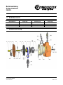
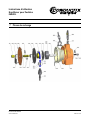
7 Ersatzteilzeichnung ..................................................................................................................................................................... 6

Betriebsanleitung
Schlauchbalancer
040409-
BAL0400-0029b-DE/EN/FR
www.conductix.com Seite 4 von 15
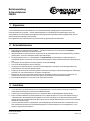
1 Allgemeines
Vor der Inbetriebnahme des Schlauchbalancers muss die Betriebsanleitung sorgfältig gelesen und beachtet werden.
Der Schlauchbalancer Typ 040409-... dient der Gewichtsentlastung von handgeführten Druckluftwerkzeugen. Durch den
Schlauchbalancer wird die Handhabung handgeführter Werkzeuge wesentlich erleichtert. Die Rückzugkräfte bleiben über die
gesamte Schlauchauszugslänge nahezu konstant.
Der Traglastbereich des Schlauchbalancers ist je nach Ausführung gemäß Typenschild differenziert.
2 Sicherheitshinweise
• Jede Änderung des Schlauchbalancers 040409-.... und dessen Zubehörs darf nur mit ausdrücklicher schriftlicher
Zustimmung der Herstellerfirma durchgeführt werden.
• Gefahrloses Arbeiten mit dem Gerät ist nur möglich, wenn Sie die Sicherheitshinweise und die Betriebsanleitung vollständig
gelesen haben, und die darin enthaltenen Anweisungen strikt befolgen.
• Der Schlauchbalancer darf nur von ausgebildetem und eingewiesenem Personal betrieben, installiert, gewartet und
instandgesetzt werden. Das Personal muss über die bei diesen Arbeiten eventuell auftretenden Gefahren unterrichtet worden
sein.
• Das Zerlegen des Federgehäuses ist äußerst gefährlich und ist strikt untersagt.
• Last nur bei voll eingezogenem Schlauch abhängen.
• Der Schlauch des Schlauchbalancers ist periodisch auf Beschädigungen zu überprüfen. Ein beschädigter Schlauch am
Schlauchbalancer darf nicht weiter betrieben werden.
• Aufhängung, Absturzsicherung und Sicherungskette sind ständig zu überwachen. Sofern Beschädigungen bzw. Abnützungen
erkennbar sind, ist der Schlauchbalancer unverzüglich auszutauschen.
• Beachten Sie, dass ein Zurückschnellen des Schlauches in unbelastetem Zustand für Personen sehr gefährlich ist und
außerdem wird die Feder zerstört. Die maximale Traglast laut Typenschild darf nicht überschritten werden.
• Bei Instandhaltungsarbeiten muss die Feder vorab völlig entspannt werden.
3 Installation
• Vor der Einrichtung des Schlauchbalancers muss sichergestellt werden, dass die ortsfeste Vorrichtung, an welcher der
Schlauchbalancer befestigt wird eine ausreichende Stabilität aufweist.
• Ausführungen mit Kunststoffgehäuse dürfen nicht in unmittelbarer Nähe von Warmluftgebläsen platziert werden.
• Einem eventuellen Herabfallen des Schlauchbalancers muss (entsprechend DIN 15112) durch eine Absturzsicherung (3)
vorgebeugt werden. Die mitgelieferte Sicherungskette (4) muss dazu unabhängig von der Balanceraufhängung ortsfest
gesichert werden. Der mögliche Fallweg darf dabei maximal 100 mm betragen. Bitte achten Sie auch hier auf die notwendige
Stabilität der ortsfesten Anlage.
• Um eine einwandfreie Funktion zu gewährleisten, darf die Beweglichkeit des Schlauchbalancers im Arbeitsbereich durch
diese zusätzliche Sicherung jedoch nicht beeinträchtigt werden. Der Schlauchbalancer muss frei beweglich sein, um ein
Pendeln in Zugrichtung zu ermöglichen.

Betriebsanleitung
Schlauchbalancer
040409-
BAL0400-0029b-DE/EN/FR
www.conductix.com Seite 5 von 15
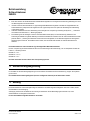
• Eine durch Absturz des Schlauchbalancers belastete Sicherungskette ist unverzüglich auszuwechseln; gleichzeitig muss dann
das Balancergehäuse mit ersetzt werden.
• Im Werk wurde der Schlauchbalancer auf Typ/-bauartgemäße Maximallast eingestellt. Innerhalb des Traglastbereichs des
Schlauchbalancers (entsprechend der Angaben auf dem Typenschild) kann auch später eine Einstellung der Federleistung
vorgenommen werden.
• Leichteren Arbeitslasten wird die Federleistung durch Verringern der Vorspannung in Richtung des Symbols „-„ , schwereren
durch drehen der Federraste in „+“ Richtung angepasst.
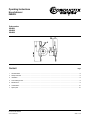
• Zur Einstellung die Last anhängen und einen Innensechskantschlüssel (6mm) auf die Federraste (6) aufstecken. Den
Schlüssel gut festhalten und gemäß Abbildung auf dem Schlauchbalancer eindrücken. Auf den Innensechskantschlüssel wirkt
jetzt eine Kraft in „-„ Richtung der Federraste. Dieser Kraft so weit nachgeben, bis ein Gewichtsausgleich der anhängenden
Arbeitslast genau erreicht ist. Anschließend darauf achten, dass die Federraste einrastet und Innensechskantschlüssel
abziehen.
Den Schlauchbalancer nicht unterhalb der Typ-/bauartgemäßen Minimallast betreiben!
Die max. Vorspannung des Schlauchbalancers wird durch X Umdrehungen der Federraste (6) vom voll entspannten Zustand der
Federn in „+“ Richtung erreicht:
040409-1 X = ca. 4
040409-2 X = ca. 2½
040409-3 X = ca. 2
Die Feder nicht weiter als bis zu dieser max. Vorspannung spannen!
4 Schlaucheinzugsbegrenzung
Ein Verstellen der Schlaucheinzugsbegrenzung ist durch einfaches Verschieben der Schlauchklemme (5) möglich. Sie ist jeweils
gut zu sichern.
Die maximale Schlauchauszugslänge darf (auch bei verlängertem Schlauch) nicht überschritten werden.
5 Wartung
Der Schlauchbalancer ist einer ständigen Pflege zu unterziehen. Alle außen liegenden beweglichen Teile sind zu fetten, ebenso
die Reibstellen an der Aufhängung.
Aufhängung und Schlauch des Balancers sind ständig zu überwachen. Sofern Beschädigungen erkennbar sind, ist der
Schlauchbalancer unverzüglich auszutauschen.
Es sind ausschließlich Original-Ersatzteile zu verwenden.

Betriebsanleitung
Schlauchbalancer
040409-
BAL0400-0029b-DE/EN/FR
www.conductix.com Seite 6 von 15
6 Gerätekennwerte
Bestell-Nummer
Traglast (kg)
Seilauszug (m)
Gewicht (kg)
040409-1
0,4 – 1,2
0,8
1,2
040409-2
1,2 – 2,2
0,8
1,3
040409-3
2,2 – 3,0
0,8
1,4
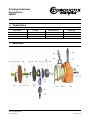
7 Ersatzteilzeichnung

Operating Instructions
Hose balancer
040409-
BAL0400-0029b-DE/EN/FR
www.conductix.com Seite 7 von 15
Order number
04040
9-1
040409
-2
040409
-3
Content
Page
1 General details ............................................................................................................................................................................ 8
2 Safety instruction ......................................................................................................................................................................... 8
3 Installation ................................................................................................................................................................................... 8
4 Hose drawing-in limit ................................................................................................................................................................... 9
5 Maintenance ................................................................................................................................................................................ 9
6 Caracteristics ............................................................................................................................................................................. 10
7 Spare parts ................................................................................................................................................................................ 10

Operating Instructions
Hose balancer
040409-
BAL0400-0029b-DE/EN/FR
www.conductix.com Seite 8 von 15
1 General details
Before installing the hose balancer read and follow carefully the operating instruction.
The type 040409-... is made for the unloading of hand-operated compressed air tools.
This device makes the handling of hand-operated tools considerably easier.
The retracting forces are kept nearly constant throughout the complete hose length.
The load capacity depends on the type of the balancer and is specified on each type plate.
2 Safety instruction
• Any modification of the balancer 040409-... and of its accessories has to be agreed before execution, through the producer in
written form.
• A safe working with this device can only be guaranteed, subject to having read and strictly followed the complete safety and
operation instructions.
• The hose balancer can only be used, installed, maintained and put into service through skilled and authorised persons. The
staff has to be informed about the possible risks.
• The disassembling of the balancer housing is very dangerous and strictly forbidden.
• Take off the load only with completely retracted wire !
• The hose of the balancer has to be periodically controlled to detect possible damages.
A damaged hose has to be replaced immediately.
• The suspension, the anti fall guard and the safety chain must be watched permanently.
If damages or wears are noticed, the hose balancer has to be replaced immediately.
• NOTICE: A resile of an unloaded hose may cause personal injury or damage the spring!
Never exceed the maximum load stated on the type plate!
• Before beginning of the maintenance work, make sure that the spring has been completely released.
3 Installation
• Before installing the hose balancer, make sure that the provided suspension, on which it will be attached, is stabile and
strong enough.
• Nether install a type with a plastic housing in the near of a hot-air blower.
• A preventive anti fall device (3) has to be installed according to DIN 15112.
• The provided safety chain (4) has to be secured separately, i.e. nether secured on the original balancer suspension !
The maximum possible trail of fall must never exceed 100 mm!
Even there, make sure that the support is adequate.
• This additional anti fall devise must not perturb the mobility of the hose balancer, which must be freely movable toward the
pulling direction.
• A fully worn chain (through a falling hose balancer) must be changed immediately;
the balancer housing has to be changed at the same time.

Operating Instructions
Hose balancer
040409-
BAL0400-0029b-DE/EN/FR
www.conductix.com Seite 9 von 15
• The balancer specific max. load has been pre-adjusted on each hose balancer.
It can be readjusted at site, within the specification of the type plate and according to the customer needs.
Adjustment:
- For lighter loads, reduce the initial tension of the spring by turning toward “-“.
For heavier loads, increase the initial tension by turning towards “+”.
- For the adjustment, attach the load on the balancer and plug an allen-key (6 mm) on
the spring shaft (6). Than hold the key tightly and press it on the hose balancer as shown
on the picture. When the load has reached his counter weight, make sure the spring
snaps in and then take off the allen-key.
Never operate the balancer under the min. load mentioned on the type plate !
You can get the max. initial tension by turning the spring shaft (6) n times towards “+”:
040409-1 n = approx. 4
040409-2 n = approx. 2½
040409-3 n = approx. 2
Never stress the spring further to this max. values!
4 Hose drawing-in limit
For readjusting the hose drawing-in limit, simply move the hose clamp (5) which is easy to be re-secured.
Never exceed the max. hose drawing-in length (also if the hose has been extended)!
5 Maintenance
The outside flexible parts and the wear points on the suspension have to be greased.
The suspension and the hose have to be kept in view permanently.
If damages are noticed, the hose balancer has to be replaced immediately.
Use exclusively genuine spare parts.

Operating Instructions
Hose balancer
040409-
BAL0400-0029b-DE/EN/FR
www.conductix.com Seite 10 von 15
6 Caracteristics
Order number
Load (kg)
Rope pull-off (m)
Weight (kg)
040409-1
0,4 – 1,2
0,8
1,2
040409-2
1,2 – 2,2
0,8
1,3
040409-3
2,2 – 3,0
0,8
1,4
7 Spare parts

Instructions d’utilisation
Equilibreur pour flexibles
040409-
BAL0400-0029b-DE/EN/FR
www.conductix.com Seite 11 von 15
Numéro de commande
040409
-1
040409
-2
040409
-3
Sommaire
Page
1 Généralités ................................................................................................................................................................................ 12
2 Instructions de sécurité .............................................................................................................................................................. 12
3 Installation ................................................................................................................................................................................. 12
4 Limite d’enroulage du flexible .................................................................................................................................................... 13
5 Maintenance .............................................................................................................................................................................. 13
6 Caractéristiques ......................................................................................................................................................................... 13
7 Pièces de rechange ................................................................................................................................................................... 14

Instructions d’utilisation
Equilibreur pour flexibles
040409-
BAL0400-0029b-DE/EN/FR
www.conductix.com Seite 12 von 15
1 Généralités
Avant toute installation bien lire et suivre scrupuleusement les instructions d’utilisation.
L’équilibreur 040409-... facilite considérablement le maniement les d’outils à air comprimé.
Les forces sont quasiment constantes sur toute la longueur du flexible.
La capacité de l’équilibreur dépend de son type (voir la plaque d’identification).
2 Instructions de sécurité
• Toute modification de l’équilibreur 040409-... et de ses accessoires doit être agréée au préalable et par écrit par le
constructeur.
• Une utilisation en toute sécurité n’est garantie qu’à condition d’avoir lu et suivi toutes les instructions de sécurité et
d’utilisation.
• L’utilisation, l’installation, la mise en service ainsi que les travaux de maintenance doivent être exécutés par des personnes
formées et autorisées à les faire. Il convient de les informer des risques éventuels.
• Démonter le boîtier de l’équilibreur peut être extrêmement dangereux et est donc strictement interdit.
• Ne décrocher la charge que si le câble est complètement rentré.
• Contrôler périodiquement l’équilibreur pour détecter d’éventuels dommages.
Changer immédiatement tout flexible endommagé.
• La suspension, le dispositif et la chaîne de sécurité doivent être contrôlés continuellement. Si des dommages ou des usures
sont constatés, l’équilibreur doit être remplacé immédiatement.
• Attention!
Le retour d’un flexible pourrait mettre en danger le personnel et causer de sérieux dégâts matériels. Ne jamais dépasser la
capacité maximale indiquée sur la plaque.
• Avant tout travail de maintenance, s’assurer que le ressort est totalement relâché.
3 Installation
• Avant d’installer l’équilibreur, s’assurer de la solidité et de la stabilité du support fourni.
• Ne jamais installer un équilibreur avec un boîtier en plastique à proximité d’une soufflerie d’air chaud.
• Un dispositif de sécurité (3) préventif doit être installé, selon DIN 15112.
• Sécuriser séparément la chaîne de sécurité (4) fournie, c.à.d. ne jamais l’attacher sur la suspension d’origine !
• La distance de chute maximale ne doit pas être supérieure à 100 mm. Là aussi, il convient de s’assurer que le support est
adéquat.
• Ce dispositif de sécurité supplémentaire ne doit en aucun cas perturber le bon fonctionnement de l’équilibreur, qui doit rester
aisément déplaçable dans le sens de la traction.
• Une chaîne ayant subie un choc provoqué par la chute de l’équilibreur doit être remplacée immédiatement. Il en va de
même pour le boîtier.

Instructions d’utilisation
Equilibreur pour flexibles
040409-
BAL0400-0029b-DE/EN/FR
www.conductix.com Seite 13 von 15
• La capacité maximale spécifique à chaque équilibreur a été préréglée en atelier. Elle peut être réajustée sur place, en
conformité avec les indications données sur sa plaque d’identification, et selon les besoins de l’utilisateur.
• Ajustage:
- Pour une charge moindre, réduire la tension initiale du ressort en tournant
vers « - « . Pour une charge plus importante, augmenter la
tension en tournant ver « + ».
- Placer la charge sur l’équilibreur et introduire une clef (6 mm) sur le cliquet du ressort
(6). Tenir fermement la clef et la pousser comme décrit sur le dessin. Quand la charge
est en équilibre, s’assurer que le ressort s’enclenche et retirer la clef.
Ne jamais faire fonctionner l’équilibreur en dessous des valeurs minimales mentionnées sur la plaque.
Tourner le cliquet du ressort (6) x-fois vers « + » .
Pour obtenir la tension initiale maximale :
040409-1 x = env. 4
040409-2 x = env. 2½
040409-3 x = env. 2
Ne jamais dépasser ces valeurs !
4 Limite d’enroulage du flexible
Pour réajuster la limite d’enroulage, déplacer simplement la borne (5) qui peut être facilement re-sécurisée.
Ne jamais dépasser la longueur maximale, même si le flexible a été rallongé!
5 Maintenance
Graisser les pièces extérieures du flexible et les points de frictions.
Garder à l’oeil en permanence la suspension et le flexible.
En cas de dommage, remplacer immédiatement l’équilibreur.
Utiliser exclusivement des pièces d’origine.
6 Caractéristiques
Numéro de commande
Charge (kg)
Course du câble (m)
Poids (kg)
040409-1
0,4 – 1,2
0,8
1,2
040409-2
1,2 – 2,2
0,8
1,3
040409-3
2,2 – 3,0
0,8
1,4

Instructions d’utilisation
Equilibreur pour flexibles
040409-
BAL0400-0029b-DE/EN/FR
www.conductix.com Seite 14 von 15
7 Pièces de rechange

Instructions d’utilisation
Equilibreur pour flexibles
040409-
BAL0400-0029b-DE/EN/FR
www.conductix.com Seite 15 von 15
Conductix-Wampfler GmbH
Rheinstraße 27 + 33
79576 Weil am Rhein - Märkt
Germany
Phone: +49 (0) 7621 662-0
Fax: +49 (0) 7621 662-144
www.conductix.com
Importer for the United Kingdom:
Conductix-Wampfler Ltd.
1, Michigan Avenue
Salford
M50 2GY
United Kingdom
Phone: +44 161 8480161
Fax: +44 161 8737017
www.conductix.com
-
 1
1
-
 2
2
-
 3
3
-
 4
4
-
 5
5
-
 6
6
-
 7
7
-
 8
8
-
 9
9
-
 10
10
-
 11
11
-
 12
12
-
 13
13
-
 14
14
-
 15
15


Conductix Wampfler Hose Balancers Benutzerhandbuch
- Typ
- Benutzerhandbuch
in anderen Sprachen
Verwandte Artikel


Andere Dokumente
-
 CONDUCTIX 040871 Benutzerhandbuch
-
 CONDUCTIX BAL0400 Benutzerhandbuch
-
 CONDUCTIX 040836-02 Benutzerhandbuch
-
Ingersoll-Rand EA Series Produktinformation
-
CONDUCTIX 040804 Benutzerhandbuch
-
Snap-On Sun SWB 200 Benutzerhandbuch
-
-
-
GYS RENOV CABLE PTI-PRO 220V Bedienungsanleitung
-
 Reely 1511388 Bedienungsanleitung


