Selve SecuBlock/SecuBlock XL Bedienungsanleitung
- Typ
- Bedienungsanleitung

Secu Fix dient zur Verbindung von Rollläden mit Achtkant-Stahlwellen
SW 60. Anderweitige Anwendungen sollten nur nach Rücksprache mit
Selve erfolgen. Die Angaben dieser Anleitung basieren auf unseren derzeitigen
Kentnissen und Erfahrungen. Sie befreien den Anwender wegen der Fülle
möglicher Einflüsse bei Einbau und Betrieb nicht vor eigenen Prüfungen und
Versuchen. Eine rechtlich verbindliche Zusicherung bestimmter Eigenschaften
oder die Eignung für einen konkreten Einsatzzweck kann aus unserern Anga-
ben nicht abgeleitet werden. Geltende Gesetze und Bestimmungen sind vom
Empfänger in eigener Verantwortung zu beachten.
Secu Fix ist in erster Linie für den Einsatz mit drehmoment-abhängig
abschaltenden Motoren vorgesehen. Bei Verwendung mit Antrieben
ohne Auflaufschutz (Spindelentabschaltung) ist auf korrekte Einstel-
lung der Endlagen zu achten, da sonst das System beschädigt werden
kann. Die Funktion ist nur mit mindestens 2 Wellenerbindern gege-
ben.
Clipmontage:
Die Wellenverbinder werden schraublos über die rechteckigen Ausstanzun-
gen (5,5 mm x 8,0 mm) mit der Achtkantstahlwelle SW 60 verbunden.
Hierzu ist ein präzieser Lochabstand von 60 mm erforderlich. Die Haken sind
in die Ausstanzungen S der Welle zu legen und durch wenden des Drehrie-
gels R um 90° in Pfeilrichtung mit Hilfe einer Münze o.ä zu verbinden.
Der Riegel rastet ein.
Zur Demontage Drehriegel um 90° zurückdrehen.
Die Rollladenhöhe ist so zu wählen das der obere Stab bei geschlossenem
Rollladen mindestens zur Hälfte der Profilhöhe in der der Führungschiene
verbleibt. Sind zu viel Stäbe vorhanden kommt es zur Funktionsbeein-
trächtigung bzw. zur Beschädigung der Anlage. Länge des Verbinders
(Anzahl der Glieder) und Rollladenhöhe sind so abzustimmen das Secufix
das obere Profil nach unten in die Führungsschiene drückt.
D
955254 BA. D 08.2017 10.000
SELVE GmbH & Co. KG · Werdohler Landstraße 286 · D-58513 Lüdenscheid
Telefon +49 (2351)925-0 · Telefax +49 (23 51) 9 25 -1 11 · www.selve.de · inf[email protected]
Einbauanleitung für Starre Wellenverbinder Secu Fix
Ç
U
Die Hochschiebesicherung SecuBlock / SecuBlock XL dient der Verbindung von
Rollläden mit Achtkantstahlwellen. Anderwei ge Anwendungen sollten nur
nach Rücksprache mit SELVE erfolgen. Die Angaben dieser Anleitung basie-
ren auf unseren derzei gen Kenntnissen und Erfahrungen. Sie befreien den
Anwender wegen der Fülle möglicher Einfl üsse bei Einbau und Betrieb nicht
vor eigenen Prüfungen und Versuchen. Eine rechtlich verbindliche Zusicherung
bes mmter Eigenscha en oder die Eignung für einen konkreten Einsatzzweck
kann aus diesen Angaben nicht abgeleitet werden. Geltende Gesetze und Be-
s mmungen sind vom Empfänger in eigener Verantwortung zu beachten.
SecuBlock ist in erster Linie für den Einsatz mit drehmomentabhängig
abschaltenden Motoren vorgesehen. Bei Verwendung mit Antrieben ohne
Aufl aufschutz (Spindelendabschaltung) ist auf korrekte Einstellung der End-
lagen zu achten, da sonst das Gesamtsystem beschädigt werden kann. Die
Funk on ist nur mit mindestens zwei Hochschiebesicherungen gegeben.
Beim Einsatz von SecuBlock XL im Bereich von Rolltoren sind die einschlägigen
Tornormen zu beachten. Im Rollladenbereich gelten die in der Din EN 13659
vorgegebenen Richtlinien. Die in der TR 104 vorgegebenen Werte zur
Belastbarkeit der Welle (Durchbiegung) sind einzuhalten.
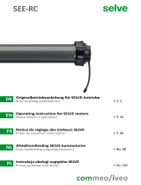
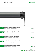
Die Hochschiebesicherungen SecuBlock rapid (mit Drehverschluss) werden
schraublos über die rechteckigen Ausstanzungen (5,5 mm x 8,0 mm) mit
der Achtkantstahlwelle verbunden. Hierzu ist ein präziser
Lochabstand von 60 mm erforderlich.
Die Haken werden dafür in die Ausstanzungen „S“ der Welle gelegt.
Durch Drehen des Drehriegels „R“ um 30° in Pfeilrichtung - z.B. mit Hilfe
einer Münze - werden diese fest mit der Achtkantstahlwelle verbunden.
Der Riegel rastet ein.
Zur Demontage den Drehriegel um 30° zurückdrehen.
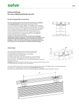
Beim Einbau der Hochschiebesicherung ist darauf zu achten, dass die
Schrauben den Motor nicht beschädigen. Rich ge Schraubenlänge
verwenden (empfohlen für Stahlwelle SW 60/70: DIN 7981 FH 3,5x6,5 mm).
Die ersten Hochschiebesicherungen links und rechts werden bei der Montage soweit wie möglich außen an der Welle angebracht.
Der Abstand „Y“ zwischen den Hochschiebesicherungen darf maximal 800 mm betragen.
Bei leichten Kunststoff -Rollläden sind auf Grund der geringeren Stablität ggf. kleinere Abstände zu wählen.
Einbauanleitung
für Hochschiebesicherung SecuBlock / SecuBlock XL
Bes mmungsgemäße Verwendung:
Clipmontage SecuBlock rapid:
Schraubmontage SecuBlock zum Anschrauben:

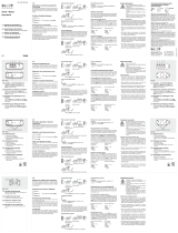
Die Rollladenhöhe ist so zu wählen, dass der oberste Rollladenstab bei
geschlossenem Rollladen bis mindestens zur Häl e der Profi lhöhe in der
der Führungschiene verbleibt. Sind zu viel Stäbe vorhanden, kommt es zur
Funk onsbeeinträch gung bzw. zur Beschädigung der Anlage. Die Länge
der Hochschiebesicherungen SecuBlock (Anzahl der Glieder) und die
Rollladenhöhe sind so abzus mmen, dass SecuBlock das obere Profi l nach
unten in die Führungsschiene drückt.
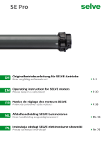
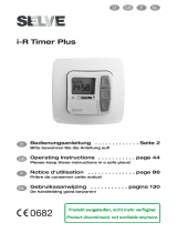
Die unten aufgeführte Tabelle hil bei der Auswahl der rich gen
SecuBlock-Version für die jeweilige EInbausitua on.
In Abhängigkeit vom Abstand „X“ des obersten Rollladenstabs zur
Achtkantstahlwelle muss eine bes mmte Länge der
Hochschiebesicherung SecuBlock gewählt werden (Anzahl der Glieder).
Achtung! Die hier angegebenen Daten können je nach Kasten- und
Profi lausführung abweichen. Jeder Rollladenhersteller muss für seinen
Anwendungsfall die op male Kombina on individuell festlegen.
Einsatzbereich Clipmontage: Achtkant-Stahlwellen SW 40, SW 50, SW 60
Einsatzbereich Clipmontage: Achtkant-Stahlwellen SW 60 x 0,9 mm bis SW 70 x 1,5 mm
Bei Einsatz von Hochschiebesicherungen SecuBlock oder SecuBlock XL mit Maxi (Neubau) Rollladenprofi len
sind Einschubprofi le Art. Nr. 289122 bzw. 289123 notwendig.
Technische Änderungen vorbehalten.
Einbauhinweise:
Einbauempfehlung SecuBlock XL:
Einbauempfehlung SecuBlock:
Version Art.-Nr.
Clipmont.
Art.-Nr. zum
Anschrauben
Abstand „X“ Motorleistung Behanggewicht
SecuBlock ohne
Zwischenglied
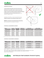
28 95 09 28 96 09 35 – 65 mm max. 4 Nm pro SecuBlock max. 8 kg pro SecuBlock
SecuBlock 1-gliedrig 28 95 10 28 96 10 60 – 90 mm max. 4 Nm pro SecuBlock max. 8 kg pro SecuBlock
SecuBlock 2-gliedrig 28 95 11 28 96 11 85 – 115 mm max. 4 Nm pro SecuBlock max. 8 kg pro SecuBlock
SecuBlock 3-gliedrig 28 95 12 28 96 12 110 – 140 mm max. 4 Nm pro SecuBlock max. 8 kg pro SecuBlock
SecuBlock 4-gliedrig 28 95 13 28 96 13 135 – 165 mm max. 4 Nm pro SecuBlock max. 8 kg pro SecuBlock
Version Art.-Nr.
Clipmont.
Art.-Nr. zum
Anschrauben
Abstand „X“ Motorleistung Behanggewicht
SecuBlock XL
1-gliedrig
28 95 40 28 96 40 80 – 115 mm max. 6 Nm pro
SecuBlock XL
max. 12 kg pro
SecuBlock XL
SecuBlock XL
2-gliedrig
28 95 41 28 96 41 110 – 145 mm max. 6 Nm pro
SecuBlock XL
max. 12 kg pro
SecuBlock XL
SecuBlock XL
3-gliedrig
28 95 42 28 96 42 140 – 175 mm max. 6 Nm pro
SecuBlock XL
max. 12 kg pro
SecuBlock XL
SELVE GmbH & Co. KG · Werdohler Landstraße 286 · 58513 Lüdenscheid · Germany
Telefon +49 (2351)925-0 · Telefax +49 (2351)925-111 · www.selve.de · [email protected]
Secu Fix dient zur Verbindung von Rollläden mit Achtkant-Stahlwellen
SW 60. Anderweitige Anwendungen sollten nur nach Rücksprache mit
Selve erfolgen. Die Angaben dieser Anleitung basieren auf unseren derzeitigen
Kentnissen und Erfahrungen. Sie befreien den Anwender wegen der Fülle
möglicher Einflüsse bei Einbau und Betrieb nicht vor eigenen Prüfungen und
Versuchen. Eine rechtlich verbindliche Zusicherung bestimmter Eigenschaften
oder die Eignung für einen konkreten Einsatzzweck kann aus unserern Anga-
ben nicht abgeleitet werden. Geltende Gesetze und Bestimmungen sind vom
Empfänger in eigener Verantwortung zu beachten.
Secu Fix ist in erster Linie für den Einsatz mit drehmoment-abhängig
abschaltenden Motoren vorgesehen. Bei Verwendung mit Antrieben
ohne Auflaufschutz (Spindelentabschaltung) ist auf korrekte Einstel-
lung der Endlagen zu achten, da sonst das System beschädigt werden
kann. Die Funktion ist nur mit mindestens 2 Wellenerbindern gege-
ben.
Clipmontage:
Die Wellenverbinder werden schraublos über die rechteckigen Ausstanzun-
gen (5,5 mm x 8,0 mm) mit der Achtkantstahlwelle SW 60 verbunden.
Hierzu ist ein präzieser Lochabstand von 60 mm erforderlich. Die Haken sind
in die Ausstanzungen S der Welle zu legen und durch wenden des Drehrie-
gels R um 90° in Pfeilrichtung mit Hilfe einer Münze o.ä zu verbinden.
Der Riegel rastet ein.
Zur Demontage Drehriegel um 90° zurückdrehen.
Die Rollladenhöhe ist so zu wählen das der obere Stab bei geschlossenem
Rollladen mindestens zur Hälfte der Profilhöhe in der der Führungschiene
verbleibt. Sind zu viel Stäbe vorhanden kommt es zur Funktionsbeein-
trächtigung bzw. zur Beschädigung der Anlage. Länge des Verbinders
(Anzahl der Glieder) und Rollladenhöhe sind so abzustimmen das Secufix
das obere Profil nach unten in die Führungsschiene drückt.
D
955254 BA. D 08.2017 10.000
SELVE GmbH & Co. KG · Werdohler Landstraße 286 · D-58513 Lüdenscheid
Telefon +49 (2351)925-0 · Telefax +49 (23 51) 9 25 -1 11 · www.selve.de · inf[email protected]
Einbauanleitung für Starre Wellenverbinder Secu Fix
Ç
U

The burglar-proof fi xa on SecuBlock / SecuBlock XL is used for the connec on
of roller shu ers with octagonal steel sha s. Other applica ons should only be
made a er consulta on with SELVE. The informa on of this instruc on base on
our current knowledge and experiences. They do not release the user from his
own test and trials due to the abundance of possible impacts during installa on
and opera on. A legally binding assurance of certain features or the
suitability for a specifi c purpose can not be derived from our informa on.
Applicable laws and regula ons have to be observed by the recipient on its
own responsibility.
SecuBlock / SecuBlock XL is primarily intended for the use with torque
dependent switching off drives. When using with drives without overrun
protec on (spindle end limit stop) you have to ensure that the end limit
posi ons are set correctly, as otherwise the en re system can be damaged.
The func on is only possible with the use of at least two burglar-proof fi xa ons.
When using SecuBlock XL in the fi eld of roller doors, the relevant door standards
must be observed. In the roller shu er fi eld, the guidelines specifi ed in Din EN
13659 apply. The values specifi ed in TR 104 for the load-bearing capacity of the
sha (defl ec on) must be observed.
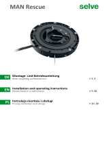
The burglar-proof fi xa ons SecuBlock / SecuBlock XL are screwlessly
connected to the octagonal steel sha via the rectangular cutouts
(5.5 mm x 8.0 mm). This requires a precise hole spacing of 60 mm.
The hooks are placed in the punching out „S“ of the sha . By turning the
twist lock „R“ by 30° in the direc on of the arrow - e.g. with the help of a
coin - these are fi rmly connected with the octagonal steel sha .
The lock snaps into place.
To disassemble, turn the twist lock by 30°.
When installing with screws please make sure that the outside of the motor
will not come into contact with the screws.
Recommended screws for steel sha 60 / 70: DIN 7981 FH 3.5 x 6.5.
When fi ng the fi rst burglar-proof fi xa ons on the le and on the right they have to be assembled outside of the sha as far as possible.
The distance „Y“ between the springs may not exceed 800 mm. For light plas c roller shu ers, smaller distances may have to be
selected due to the lower stability.
Installa on instruc ons
for burglar-proof fi xa on SecuBlock / SecuBlock XL
Intended use:
Clip assembly SecuBlock rapid:
Screw assembly SecuBlock:
EN

The roller shu er height should be selected so that the top roller
shu er bar remains in the guide rail up to at least half of the profi le
height when the roller shu er is closed. If there are too many bars,
it will come to a func onal impairment or rather the system will be
damaged. The length of the burglar-proof fi xa on SecuBlock / SecuBlock XL
(number of parts) and the roller shu er height must be adjusted so that the
SecuBlock presses the upper profi le down into the guide rail.
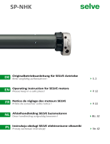
The table below helps to select the right SecuBlock version for the
respec ve installa on situa on.
Depending on the distance „X“ of the top roller shu er bar to the
octagonal steel sha , a certain length of the burglar-proof fi xa on
SecuBlock / SecuBlock XL must be selected (number of parts).
A en on! The data given here may diff er depending on the box and
profi le version. Every roller shu er manufacturer must determine the
op mal combina on for their applica on individually.
Range of applica on: octagonal steel sha s 40 / 50 / 60 mm
Range of applica on: octagonal steel sha s 60 x 0,9 mm up to 70 x 1,5 mm
When using the burglar-proof fi xa on SecuBlock / SecuBlock XL with maxi (build-in system) roller shu er profi les,
slide-in profi les / adapter profi les with ar cle number 289122 or rather 289123 are necessary.
Subject to technical modifi ca ons.
Installa on Instruc ons:
Installa on recommenda on SecuBlock XL:
Installa on recommenda on SecuBlock:
Version Art. No.
Art. No. screw
on version
distance “X“ Drive power System weight
SecuBlock without
intermediate part
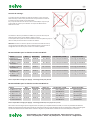
28 95 09 28 96 09 35 – 65 mm max. 4 Nm per SecuBlock max. 8 kg per SecuBlock
SecuBlock 1-parts 28 95 10 28 96 10 60 – 90 mm max. 4 Nm per SecuBlock max. 8 kg per SecuBlock
SecuBlock 2-parts 28 95 11 28 96 11 85 – 115 mm max. 4 Nm per SecuBlock max. 8 kg per SecuBlock
SecuBlock 3-parts 28 95 12 28 96 12 110 – 140 mm max. 4 Nm per SecuBlock max. 8 kg per SecuBlock
SecuBlock 4-parts 28 95 13 28 96 13 135 – 165 mm max. 4 Nm per SecuBlock max. 8 kg per SecuBlock
Version Art. No.
Art. No. screw
on version
distance “X“ Drive power System weight
SecuBlock XL
1-parts
28 95 40 28 96 40 80 – 115 mm max. 6 Nm per
SecuBlock XL
max. 12 kg per
SecuBlock XL
SecuBlock XL
2-parts
28 95 41 28 96 41 110 – 145 mm max. 6 Nm per
SecuBlock XL
max. 12 kg per
SecuBlock XL
SecuBlock XL
3-parts
28 95 42 28 96 42 140 – 175 mm max. 6 Nm per
SecuBlock XL
max. 12 kg per
SecuBlock XL
SELVE GmbH & Co. KG · Werdohler Landstraße 286 · 58513 Lüdenscheid · Germany
Telefon +49 (2351)925-0 · Telefax +49 (2351)925-111 · www.selve.de · [email protected]
EN

Le verrou-automa que SecuBlock / SecuBlock XL permet de relier le tablier au tube
octogonal. Pour tout autre cas de fi gure il sera préférable de d‘abord consulter nos
services techniques. Toutes les informa ons dans ce e no ce émanent de notre
savoirfaire dans le domaine de la motorisa on et de notre expérience acquise avec
les applica ons chez nos clients.
Pour des applica ons classiques cela simplifi e la
démarche de nos clients. Pourtant
sans pourtant les exempter d‘essais de montage
et de mise en œuvre, car les types de volets sont variés selon les constructeurs.
Les indica ons rela ves aux propriétés des produits, ou à leur compa bilité pour
des applica ons concrètes, sont fournies sans engagement de notre part. Les lois et
disposi ons sont à prendre en compte par le client sous sa responsabilité.
Le SecuBlock est d‘abord des né à être u lisé comme lien rigide entre le
tube et le tablier, pour perme re à un moteur tubulaire à réglage automa-
que de déterminer lui-même et automa quement ses fi ns de course. En
cas d‘u lisa on avec des moteurs à fi n de course mécanique ou un moteur
automa que réglé en mode manuel, il faut impéra vement régler les fi ns
de course au plus juste pour éviter toute détériora on prématurée des
diff érents éléments qui composent le volet.
Il faut impéra vement u liser au minimum 2 verrou-automa ques.
Lors de l‘u lisa on de SecuBlock XL dans le domaine des portes roulantes,
il est obligatoire de respecter les normes applicables aux portes. Dans le
domaine des volets roulants, les direc ves spécifi ées dans la norme
Din EN 13659 s‘appliquent. Les valeurs indiquées dans le TR 104 pour la
capacité de charge de tube (défl exion) doivent être respectées.
Les verrou-automa ques SecuBlock / SecuBlock XL se montent sans vissage
directement dans les lumières 5.5 mm x 8.00mm du tube, grâce à ses 3
crochets. Deux fi xes en extrémités et un central pour le verrouillage et le
clippage.
Ces crochets sont mis en place lorsque le clip de verrouillage se trouve sur la
posi on S, puis on vient verrouiller le clip en le tournant de 30° en posi on R.
ce qui verrouille l‘a ache rigide sur le tube. Ce crochet central se verrouille
automa que grâce à un clip. Pour démonter l‘a ache rigide il suffi t de réaliser
l‘opéra on en sens inverse.
Lors d‘une installa on par vis, il est indispensable de veiller à ce que les vis ne
touchent pas le tube du moteur.
Vis recommandée pour tube 60 / 70: DIN 7981 FH 3.5 x 6.5.
Les verrou-automa ques sont a posi onner au plus prêt des extrémités du tube en respectant toutefois une cote Ymaximale de 800 mm.
Dans le cas où les u lise, par exemple, avec des lames PVC peu rigides il réduire la valeur Y, ou rajouter une a ache centrale.
No ce d‘u lisa on
des verrou-automa ques SecuBlock / SecuBlock XL
Préconisa ons d‘u lisa on :
Montage par clippage du SecuBlock rapid :
Montage SecuBlock par vis :
F

Le nombre de lames du tablier est défi ni de manière à ce que lorsque le
volet est fermé, le milieu de la première lame soit posi onné à l‘entrée de
la coulisse lorsque le tablier est en butée basse.
S‘il y a trop de lames dans le caisson le verrou-automa que ne pourra pas
se verrouiller et n‘assura pas sa fonc on. Au risque de détériorer des
éléments du volets.
Les tableaux ci-dessous perme ent de défi nir d’un point de mécanique et
dimensionnel la version du SecuBlock à me re en œuvre.
La cote X, mesurée à par r du crochet d‘a ache de la lame supérieure jusqu‘au
milieu du tube permet de choisir le nombre de maillons.
A en on! Les valeurs ci-dessous peuvent en fonc on des tailles de caisson,
du type de lames être diff érentes. Chaque fabricant devra en fonc on de sa
confi gura on faire ses essais pour arriver à une solu on op male.
Secteur d‘opéra on montage par clippage : Tube octagonal 40 / 50 / 60 mm
Secteur d‘opéra on montage par clippage : Tube octagonal 60 x 0,9 mm jusqu‘à 70 x 1,5 mm
Dans certains cas de montage lorsque les trappes de visite sont pe tes, pour simplifi er la fi xa on du tablier, nous avons un profi l référence 289122 ou
289123 qui permet de fi xer le tablier lorsque le tube est monté dans le coff re et qu’il est déjà équipé des verrou-automa ques. Il suffi t ainsi de faire glisser
ce profi l sur le tablier avant de le me re dans les coulisses et de glisser ces profi lés dans les crochets des verrou-automa ques à ce moment-là.
Conseils de montage:
Recommanda on pour le chiox des versions SecuBlock XL :
Recommanda on pour le chiox des versions SecuBlock :
Version Réf Réf à visser Valeur “X“ Couple adm. par A . Charge admissible
SecuBlock sans
maillon intermédiaire
28 95 09 28 96 09 35 – 65 mm max. 4 Nm par SecuBlock max. 8 kg par SecuBlock
SecuBlock 1-maillon
intermédiaire
28 95 10 28 96 10 60 – 90 mm max. 4 Nm par SecuBlock max. 8 kg par SecuBlock
SecuBlock 2-maillons
intermédiaires
28 95 11 28 96 11 85 – 115 mm max. 4 Nm par SecuBlock max. 8 kg par SecuBlock
SecuBlock 3-maillons
intermédiaires
28 95 12 28 96 12 110 – 140 mm max. 4 Nm par SecuBlock max. 8 kg par SecuBlock
SecuBlock 4-maillons
intermédiaires
28 95 13 28 96 13 135 – 165 mm max. 4 Nm par SecuBlock max. 8 kg par SecuBlock
Version Réf Réf à visser Valeur “X“ Couple adm. par A . Charge admissible
SecuBlock XL 1-mail-
lon intermédiaire
28 95 40 28 96 40 80 – 115 mm max. 6 Nm par
SecuBlock XL
max. 12 kg par
SecuBlock XL
SecuBlock XL 2-mail-
lons intermédiaires
28 95 41 28 96 41 110 – 145 mm max. 6 Nm par
SecuBlock XL
max. 12 kg par
SecuBlock XL
SecuBlock XL 3-mail-
lons intermédiaires
28 95 42 28 96 42 140 – 175 mm max. 6 Nm par
SecuBlock XL
max. 12 kg par
SecuBlock XL
SELVE GmbH & Co. KG · Werdohler Landstraße 286 · 58513 Lüdenscheid · Germany
Telefon +49 (2351)925-0 · Telefax +49 (2351)925-111 · www.selve.de · [email protected]
F

PL
Sztywne wieszaki SecuBlock służą jako połączenie pancerza rolety
z wałkiem roletowym. Wszelkie inne zastosowania muszą być skonsultowane
z SELVE. Zalecenia niniejszej instrukcji opierają się na naszej dotychczasowej
wiedzy i doświadczeniu. Ze względu na możliwości wystąpienia wielu czynników,
trudnych do przewidzenia przez producenta, instrukcja nie zwalnia montujących
i używających nasz produkt z konieczności własnej oceny zastosowania wie-
szaka i wykonania prób eksploatacyjnych.Podawane przez nas informacje nie
gwarantują wiążących prawnie
właściwości produktu, ani przydatności do konkretnych zastosowań.
Nabywca naszego produktu musi na własną odpowiedzialność przestrzegać
ewentualnych przepisów prawnych i zaleceń.
SecuBlock jest przeznaczony przede wszystkim do zastosowania z napędami
działającymi przeciążeniowo. Przy użyciu do zastosowania z napędami bez
przeciążenia (z krańcówkami ustawianymi mechanicznie), trzeba zwrócić
uwagę na prawidłowe ustawienie krańcówek, aby nie doprowadzić do
zniszczenia osłony. Konieczne jest zastosowanie minimum 2 wieszaków.
„W przypadku stosowania SecuBlock XL w bramach rolowanych należy prze-
strzegać odpowiednich norm dotyczących bram. W zakresie rolet obowiązu-
ją wytyczne zawarte w normie DIN EN 13659. Należy przestrzegać wartości
podanych w TR 104 dotyczących nośności wałka (ugięcia).”
Jeżeli wałek posiada otwory prostokątne (5,5 x 8 mm) można stosować
wieszaki z klipsem, które nie muszą być przykręcane. Aby to było możliwe
otwory w wałku roletowym powinny znajdować się w regularnych odstępach
co 60 mm.
W tym celu należy włożyć haki, znajdujące się pod spodem wieszaka, do
otworów „S“ w wałku.
Następnie należy przekręcić rygiel „R“ o 30° w kierunku strzałki - np.:
za pomocą monety - w ten sposób następuje stabilne połączenie z wałkiem
roletowym. Wypustki rygla muszą zatrzasnąć się w słyszalny sposób.
Uwaga! Przy wałku o średnicy 40 mm haki nie mogą dotykać zainstalowanego
napędu. Wieszak może zostać odpięty od wałka przez przekręcnie monety
włożonej do otworu „R“ w kierunku przeciwnym do strzałki o 30 °.
Pierwsze sztywne wieszaki należy zamontować jak najbliżej końcówek wałka. Odległość „Y“ może wynosić maxymalnie 800 mm.
W zastosowaniu przy lekkich pancerzach, ze wzglądu na mniejszą stabilność pancerza, zaleca się stosowanie wieszaków
w mniejszych odległościach od siebie.
Instrukcja obsługi dla
sztywnych wieszaków SecuBlock / SecuBlock XL
Zastosowanie zgodne z przeznaczeniam:
Montaż w wersji z klipsem:
Przy montażu wieszaków trzeba zwrócić uwagę na to aby śruby nie
uszkadzały napędu. Proszę zastosować właściwe śruby (proponujemy do
zastosowań w wałkach SW 60 / 70: DIN 7981 FH 3,5 x 6,5 mm).
Montaż w wersji do przykręcania:

Przy zamkniętej rolecie, najwyższa listwa pancerza może wystawać
z prowadnicy maksymalnie do połowy swojej wysokości.
Jeżeli w prowadnicy znajduje się zbyt wiele profi li pancerza, może to
negatywnie wpłynąć na działanie rolety lub doprowadzić do jej
uszkodzenia.
Zastosowana długość (ilość elemetów) wieszaka i wysokość rolety musi być
tak dobrana aby wieszak SecuBlock dociskał pierwszą listwę pancerza
w dół prowadnicy.
Poniższa tabelka ułatwia wybór prawidłowej wersji SecuBlock w zależności od
sytuacji montażowej. W zależności od odległości „X“ górnego profi la pancerza
do wałka roletowego powinno się stosować odpowiednią
długość wieszaka (ilość elementów).
Do zastosowania: wałek ośmiokątny SW 40, SW 50, SW 60
Do zastosowania: wałek ośmiokątny SW 60 x 0,9 mm do SW 70 x 1,5 mm
Przy zastosowaniu wieszaków SecuBlock do profi li roletowych Maxi (szerokich) konieczne jest dodatkowe zastosowanie profi li
łączących do wieszaków art. 289122 lub 289123. Zachowujemy prawo do wprowadzenia zmian technicznych.
Wskazówki montażowe:
Poleca się:
Poleca się:
Rodzaj wieszaka Numer
artykułu.
Numer artykułu
do przykręcania
Odległość „X“ Siła napędu Obciążenie
SecuBlock bez części
środkowej
28 95 09 28 96 09 35 – 65 mm max. 4 Nm pro SecuBlock max. 8 kg pro SecuBlock
SecuBlock 1-częściowy 28 95 10 28 96 10 60 – 90 mm max. 4 Nm pro SecuBlock max. 8 kg pro SecuBlock
SecuBlock 2-częściowy 28 95 11 28 96 11 85 – 115 mm max. 4 Nm pro SecuBlock max. 8 kg pro SecuBlock
SecuBlock 3-częściowy 28 95 12 28 96 12 110 – 140 mm max. 4 Nm pro SecuBlock max. 8 kg pro SecuBlock
SecuBlock 4-częściowy 28 95 13 28 96 13 135 – 165 mm max. 4 Nm pro SecuBlock max. 8 kg pro SecuBlock
Rodzaj wieszaka Numer
artykułu
Numer artykułu
do przykręcania
Odległość „X“ Siła napędu Obciążenie
SecuBlock XL
1-częściowy
28 95 40 28 96 40 80 – 115 mm max. 6 Nm pro
SecuBlock XL
max. 12 kg pro
SecuBlock XL
SecuBlock XL
2-częściowy
28 95 41 28 96 41 110 – 145 mm max. 6 Nm pro
SecuBlock XL
max. 12 kg pro
SecuBlock XL
SecuBlock XL
3-częściowy
28 95 42 28 96 42 140 – 175 mm max. 6 Nm pro
SecuBlock XL
max. 12 kg pro
SecuBlock XL
SELVE GmbH & Co. KG · Werdohler Landstraße 286 · 58513 Lüdenscheid · Germany
Telefon +49 (2351)925-0 · Telefax +49 (2351)925-111 · www.selve.de · [email protected]
955240 BA.DE EN F PL 04.2021 5.000
PL
-
 1
1
-
 2
2
-
 3
3
-
 4
4
-
 5
5
-
 6
6
-
 7
7
-
 8
8


Selve SecuBlock/SecuBlock XL Bedienungsanleitung
- Typ
- Bedienungsanleitung
in anderen Sprachen
Verwandte Artikel
-
 Selve SecuFix Bedienungsanleitung
-
 Selve SEE-com Bedienungsanleitung
-
 Selve SEE-RC Bedienungsanleitung
-
 Selve SE Pro Bedienungsanleitung
-
Selve SE Pro 2/15 Operating
-
 Selve MAN Rescue Bedienungsanleitung
-
 Selve SP-NHK, ≤ 20 Nm Bedienungsanleitung
-
 Selve SE Pro-RC Bedienungsanleitung
-
 Selve iveo Key Send Bedienungsanleitung
-
 Selve i-R Timer Plus Bedienungsanleitung


