Hitachi DH 24PD2 Handling Instructions Manual
- Kategorie
- Elektrowerkzeuge
- Typ
- Handling Instructions Manual

Rotary Hammer
Bohrhammer
Marteau perforateur
Martello perforatore
Boorhamer
Martillo perforador
Martelo perfurador
™Ê˘ÚÔ‰Ú¿·ÓÔ ÂÚÈÛÙÚÔÊÈÎfi
Read through carefully and understand these instructions before use.
Diese Anleitung vor Benutzung des Werkzeugs sorgfältig durchlesen und verstehen.
Lire soigneusement et bien assimiler ces instructions avant usage.
Prima dell’uso leggere attentamente e comprendere queste istruzioni.
Deze gebruiksaanwijzing s.v.p. voor gebruik zorgvuldig doorlezen.
Leer
cuidadosamente y comprender estas instrucciones antes del uso.
Antes de usar, leia com cuidado para assimilar estas instruções.
∆ιαάστε πρσεκτικά και κατανήσετε αυτές τις δηγίες πριν τη ρήση.
Handling instructions
Bedienungsanleitung
Mode d’emploi
Istruzioni per l’uso
Gebruiksaanwijzing
Instrucciones de manejo
Instruções de uso
δηγίες ειρισµύ
DH 24PD2
403
Code No. C99132571 N
Printed in Japan
1
2
4
6
8
3
5
7
1
1
2
3
4
4
5
Hitachi Koki Co., Ltd.
Representative office in Europe
Hitachi Power Tools Europe GmbH
Siemensring 34, 47877 Willich 1, F. R. Germany
Head office in Japan
Hitachi Koki Co., Ltd.
Shinagawa Intercity Tower A, 15-1, Konan 2-chome,
Minato-ku, Tokyo, Japan
31. 3. 2004
K. Kato
Board Director
Nederlands
EC VERKLARING VAN CONFORMITEIT
Wij verklaren onder eigen verantwoordelijkheid dat dit
produkt conform de richtlijnen of gestandardiseerde
documenten EN60745, EN55014 en EN61000-3 voldoet
aan de eisen van EEG Bepalingen 73/23/EEG, 89/336/
EEG en 98/37/EC.
Deze verklaring is van toepassing op produkten
voorzien van de CE-markeringen.
Español
DECLARACIÓN DE CONFORMIDAD DE LA CE
Declaramos bajo nuestra única responsabilidad que
este producto está de acuerdo con las normas o con
los documentos de normalización EN60745, EN55014
y EN61000-3, según indican las Directrices del Consejo
73/23/CEE, 89/336/CEE y 98/37/CE.
Esta declaración se aplica a los productos con marcas
de la CE.
Português
DECLARAÇÃO DE CONFORMIDADE CE
Declaramos, sob nossa única e inteira responsabilidade,
que este produto está de acordo com as normas ou
documentos normativos EN60745, EN55014 e EN61000-
3, em conformidade com as Diretrizes 73/23/CEE, 89/
336/CEE e 98/37/CE do Conselho.
Esta declaração se aplica aos produtos designados CE.
Ελληνικά
EK ∆ΗΛ·ΣΗ ΕΝΑΡΜΝΙΣΜΥ
∆ηλώνυµε µε απ&λυτη υπευθυν&τητα &τι αυτ& τ
πρι&ν είναι εναρµνισµέν µε τα πρ&τυπα ή τα
έγρα(α πρτύπων EN60745, EN55014 και EN61000-3
σε συµ(ωνία µε τις δηγίες τυ Συµυλίυ 73/23/
EOK, 89/336/EOK και 98/37/EK.
Αυτή η δήλωση ισύει στ πρι&ν µε τ σηµάδι CE.
English
EC DECLARATION OF CONFORMITY
We declare under our sole responsibility that this
product is in conformity with standards or standardized
documents EN60745, EN55014 and EN61000-3 in
accordance with Council Directives 73/23/EEC, 89/336/
EEC and 98/37/EC.
This declaration is applicable to the product affixed CE
marking.
Deutsch
ERKLÄRUNG ZUR KONFORMITÄT MIT CE-REGELN
Wir erklären mit alleiniger Verantwortung, daß dieses
Produkt den Standards oder standardisierten
Dokumenten EN60745, EN55014 und EN61000-3 in
Übereinstimmung mit den Direktiven des Europarats
73/23/EWG, 89/336/EWG und 98/37/CE entspricht.
Diese Erklärung gilt für Produkte, die die CE-Markierung
tragen.
Français
DECLARATION DE CONFORMITE CE
Nous déclarons sous notre seule et entière respon-
sabilité que ce produit est conforme aux normes ou
documents normalisés EN60745, EN55014 et EN61000-
3 en accord avec les Directives 73/23/CEE, 89/336/CEE
et 98/37/CE du Conseil.
Cette déclaration s’applique aux produits désignés CE.
Italiano
DICHIARAZIONE DI CONFORMITÀ CE
Si dichiara sotto nostra responsabilità che questo
prodotto è conforme agli standard o ai documenti
standardizzati EN60745, EN55014 e EN61000-3
conforme alle direttive 73/23/CEE, 89/336/CEE e 98/37/
CE del concilio.
Questa dichiarazione è applicabile ai prodotti cui sono
applicati i marchi CE.
6
7
A
@
D
C
B
R
L
R
L

3
2 76
17 18
P
Q
O
R
T
20
19
S
3
4
14
13
12
11
10
9
15
16
15 mm
H
B
B
I
C
J
C
D
H
F
L
H
I
8
8
L
1
3
R
4
G
E
B
A
I
K

3
2 76
17 18
P
Q
O
R
T
20
19
S
3
4
14
13
12
11
10
9
15
16
15 mm
H
B
B
I
C
J
C
D
H
F
L
H
I
8
8
L
1
3
R
4
G
E
B
A
I
K

4
English Deutsch Français Italiano
1
2
3
4
5
6
7
8
9
0
A
B
C
D
E
F
G
H
I
J
K
L
M
N
O
P
Q
R
S
T
Drill bit Bohrer Foret de perçage
Part of SDS-plus shank
Teii des SDS-plus Schaftes
Elément de la tige SDS plus
Front cap Vordere Abdeckung Capuchon avant
Grip Spannbacke Attache coulissante
Dust cup Staubschale Godet à poussière
Dust collector (B) Staubfänger (B)
Collecteur à poussière (B)
Push button Druckschalter Bouton-poussoir
Change lever Wahlhebel Sélecteur
Push button Druckschalter Bouton-poussoir
Side handle Handgriff Poignée laterale
Dust-collecting adapter Staubfangadapter
Adaptateur de recupération
des poussières
Hose Schlauch Tuyau
Dust bag Staubsack Sac à poussière
Rail Strebe Pince
Mounting hole Befestigungsöffnung Orifice de montage
Knob on side handle Knopf oder Seitengriff
Bouton ou poignée latérale
Attachment rod Befestigungsstab Tige de fixation
Hose attachment hole
Schlauchbefestigungsloch Trou de fixation du tuyau
Dust bag attachment hole
Staubbeutelbefestigungsloch
Trou de fixation du sac de
récupération des poussières
Wing bolt Flügelschraube Boulon à oreilles
Stopper Anschlag Butée
Cap Kappe Capuchon
Drill chuck Bohrfutter Mandrin porte-foret
Chuck adapter Bohrfutteradapter Raccord de mandrin
Chuck adapter (D) Bohrfutteradapter (D) Raccord (D) de mandrin
Bit Bohrerspitze Mèche
Socket Fassung Prise
Tape shank adapter Kegelschaftadapter
Raccord de queue conique
Cotter Dorn Clavette
Rest Auflage Support
Punta del trapano
Parte dell'asta SDS plus
Protezione davanti
Presa davanti
Contenitore a polvere
Camera a polvere (B)
Pulsante
Leva di selezione
Pulsante
Laterale
Adattatore
raccoglipolvere
Tubo
Sacca di raccolta della polvere
Binario
Foro d'inserimento della
bacchetta di arresto
Monopola o maniglia laterale
Barra di attacco
Foro di attacco del tubo
Foro di attacco del sacco
portapolvere
Bullone a galletto
Fermo
Tappo
Mandrino
Adattatore per mandrino
Adattatore (D) per mandrino
Punta
Presa
Adattatore per gambo conico
Coppiglia
Appoggio

5
Nederlands Español Português Ελληνικά
1
2
3
4
5
6
7
8
9
0
A
B
C
D
E
F
G
H
I
J
K
L
M
N
O
P
Q
R
S
T
Boorstuk Broca
Onderdeel van SDS Parte del SDS plus
Plus schacht vástago
Voorkap Cubierta frontal
Greep Sujetador
Stofvangkap Capa de polvo
Stofverzamelaar (B) Colector de polvo (B)
Drukknop Tecla
Keuzeschakelaar Palanquita selectora
Drukknop Tecla
Zijgreep Mango lateral
Adapter voor stofopvang
Adaptador para
recolección de polvo
Slang Manguera
Stofzak
Bolsa colectore de polvo
Klemrand Riel
Montagegat Agujero de montaje
Knop op zijgreep
Mando del mango lateral
Verbindingsstag Varilla de instalación
Bevestigingsopening voor Orificio de instalación de
slang la manguera
Bevestigingsopening voor
Orificio de instalación de la
stofzak
bolsa para el polvo
Vleugelmoer Paasado de palomilla
Stopper Retanedor
Afsluitdop Tapa
Boorkop Portabrocas
Boorkopadaptor
Adaptador del
portabrocas
Boorkopadaptor (D
)
Adaptador (D) del
portabrocas
Boorstuk Broca
Aansluithuls Cubo
Vernauwde Adaptador de la espiga
schachtadaptor ahusada
Cotter Chaveta
Steun Apoyo
Broca
Cabo de peça SDS-plus
Tampa da frente
Mordente
Receptáculo para poeira
Coletor de poeira (B)
Botão de pressão
Seletor
Botão de pressão
Empunhadura lateral
Adaptador para recolha
de poeiras
Mangueira
Colector de poeiras
Calha
Orifício de montagem
Botão na pega lateral
Haste de Acessório
Orifício do Acessório
Mangueira
Orifício do acessório
saco para poeiras
Parafuso tipo borboleta
Bloqueador
Tampa
Mandril
Adaptador do mandril
Adaptador do mandril
(D)
Palhetão
Encaixe
Adaptador de cabo
cônico
Cavilha
Suporte
Λεπίδα τρυπανιύ
Τµήµα τυ SDS-plus
στελέυς
Μπρστιν περίληµα
Λαή
Κύπελλ σκνης
Συλλέκτης σκνης (Β)
Κυµπί ώθησης
Μλς αλλαγής
Κυµπί ώθησης
Πλευρική λαή
Πρσαρµγέας
συλλγής σκνης
Μάνικα
Σάκς σκνης
$δηγς
$πή στήρι%ης
Βίδα πλαϊνής λαής
Βέργα πρσαρµγής
$πή πρσαρµγής
µάνικας
$πή πρσαρµγής
σάκυ σκνης
Φτερωτ µπυλνι
Στπερ
Καπάκι
Σ+ικτήρας τρυπανιύ
Πρσαρµγέας
σ+ικτήρα
Πρσαρµγέας
σ+ικτήρα (D)
Λεπίδα
Υπδή
Κωνικς πρσαρµγέας
στελέυς
Κ+της
Στήριγµα

English
6
GENERAL OPERATIONAL PRECAUTIONS
WARNING! When using electric tools, basic safety
precautions should always be followed to reduce the
risk of fire, electric shock and personal injury, including
the following.
Read all these instructions before operating this product
and save these instructions.
For safe operations:
1. Keep work area clean. Cluttered areas and benches
invite injuries.
2. Consider work area environment. Do not expose
power tools to rain. Do not use power tools in
damp or wet locations. Keep work area well lit.
Do not use power tools where there is risk to cause
fire or explosion.
3. Guard against electric shock. Avoid body contact
with earthed or grounded surfaces (e.g. pipes,
radiators, ranges, refrigerators).
4. Keep children and infirm persons away. Do not let
visitors touch the tool or extension cord. All visitors
should be kept away from work area.
5. Store idle tools. When not in use, tools should be
stored in a dry, high or locked up place, out of reach
of children and infirm persons.
6. Do not force the tool. It will do the job better and
safer at the rate for which it was intended.
7. Use the right tool. Do not force small tools or
attachments to do the job of a heavy duty tool. Do
not use tools for purposes not intended; for example,
do not use circular saw to cut tree limbs or logs.
8. Dress properly. Do not wear loose clothing or
jewelry, they can be caught in moving parts. Rubber
gloves and non-skid footwear are recommended
when working outdoors. Wear protecting hair
covering to contain long hair.
9. Use eye protection. Also use face or dust mask if
the cutting operation is dusty.
10. Connect dust extraction equipment.
If devices are provided for the connection of dust
extraction and collection facilities ensure these are
connected and properly used.
11. Do not abuse the cord. Never carry the tool by the
cord or yank it to disconnect it from the receptacle.
Keep the cord away from heat, oil and sharp edges.
12. Secure work. Use clamps or a vise to hold the work.
It is safer than using your hand and it frees both
hands to operate tool.
13. Do not overreach. Keep proper footing and balance
at all times.
14. Maintain tools with care. Keep cutting tools sharp
and clean for better and safer performance. Follow
instructions for lubrication and changing
accessories. Inspect tool cords periodically and if
damaged, have it repaired by authorized service
center. Inspect extension cords periodically and
replace, if damaged. Keep handles dry, clean, and
free from oil and grease.
15. Disconnect tools. When not in use, before servicing,
and when changing accessories such as blades,
bits and cutters.
16. Remove adjusting keys and wrenches. Form the
habit of checking to see that keys and adjusting
wrenches are removed from the tool before turning
it on.
17. Avoid unintentional starting. Do not carry a plugged-
in tool with a finger on the switch. Ensure switch is
off when plugging in.
18. Use outdoor extension leads. When tool is used
outdoors, use only extension cords intended for
outdoor use.
19. Stay alert. Watch what you are doing. Use common
sense. Do not operate tool when you are tired.
20. Check damaged parts. Before further use of the
tool, a guard or other part that is damaged should
be carefully checked to determine that it will operate
properly and perform its intended function. Check
for alignment of moving parts, free running of
moving parts, breakage of parts, mounting and any
other conditions that may affect its operation. A
guard or other part that is damaged should be
properly repaired or replaced by an authorized
service center unless otherwise indicated in this
handling instructions. Have defective switches
replaced by an authorized service center. Do not
use the tool if the switch does not turn it on and off.
21. Warning
The use of any accessory or attachment, other than
those recommended in this handling instructions,
may present a risk of personal injury.
22. Have your tool repaired by a qualified person.
This electric tool is in accordance with the relevant
safety requirements. Repairs should only be carried
out by qualified persons using original spare parts.
Otherwise this may result in considerable danger
to the user.
PRECAUTIONS ON USING ROTARY HAMMER
1. Wear earplugs to protect your ears during operation.
2. Do not touch the bit during or immediately after
operation. The bit becomes very hot during
operation and could cause serious burns.
3. Before starting to break, chip or drill into a wall,
floor or ceiling, thoroughly confirm that such items
as electric cables or conduits are not buried inside.
4. Always hold the body handle and side handle of
the power tool firmly. Otherwise the counterforce
produced may result in inaccurate and even
dangerous operation.

English
7
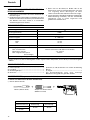
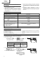
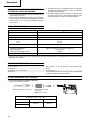
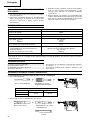
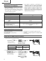
OPTIONAL ACCESSORIES (sold separately)
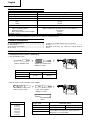
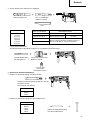
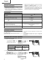
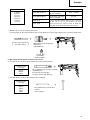
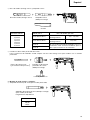
1. Drilling anchor holes (rotation + hammering)
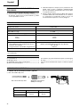
䡬 Drill bit (Slender shaft)
䡬 Drill bit (Taper shank) and taper shank adapter
Drill bit (slender shaft)
Outer diameter Effective length Overall length
3.4 mm
45 mm 90 mm
3.5 mm
SPECIFICATIONS
Voltage (by areas)* (110V, 230V)
Power Input 720W*
No-load speed 0 – 1050
min
–1
Full-load impact rate 0 – 4600
min
–1
Capacity: concrete 3.4 – 24 mm
steel 13 mm
wood 32 mm
Weight (without cord and side handle) 2.8 kg
Dust collecting adapter
Max. hole-drilling depth: 100 mm (adjustment possible between 0 and 100 mm)
Diameter of drill: 3.4 – 24 mm
Max. length of drill (overall length): 270 mm
Dustbag capacity: 0.4 liters
* Be sure to check the nameplate on product as it is subject to change by areas.
STANDARD ACCESSORIES
(1) Case (Molded plastic) ................................................. 1
(2) Side handle ................................................................. 1
(3) Dust collecting adapter .............................................. 1
(4) Dust bag ...................................................................... 1
Adapter for slender shaft
(SDS-plus shank)
Drill bit (Slender shaft)
Drill bit (Taper shank)
Taper shank adapter
(SDS-plus shank)
Cotter
Outer diameter
11.0 mm
12.3 mm
12.7 mm
14.3 mm
14.5 mm
17.5 mm
21.5 mm
Taper mode Applicable drill bit
Morse taper (No.1) Drill bit (taper shank) 11.0 ~ 17.5 mm
Morse taper (No.2) Drill bit (taper shank) 21.5 mm
A-taper Taper shank adapter formed A-taper or B-taper
is provided as an optional accessory, but the
B-taper
drill bit for it is not provided.
[Numbers (3) and (4) refer to use on concrete]
(5) Cap ............................................................................... 1
Standard accessories are subject to change without
notice.

English
8
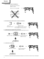
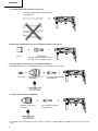
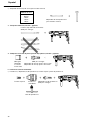
( )
Straight shank bit
for impact drill
䡬 13 mm rotary hammer chuck
For drilling operations when using a straight shank bit for impact drilling with a rotary hammer.
13 mm rotary hammer chuck
(SDS-plus shank)
Chuck wrench
䡬 Anchor setting adapter (for manual hammer)
Anchor setting adapter
(for manual Hammer)
Anchor setting adapter (SDS-plus shank)
(for rotary hammer)
Overall length: 160, 260 mm
Anchor size
W1/4”
W5/16”
W3/8”
Anchor size
W1/4”
W5/16”
W3/8”
W1/2”
W5/8”
2. Anchor setting (rotation + hammering)
䡬 Anchor setting adapter (for rotary hammer)
3. Demolishing operation (rotation + hammering)
Bull point (Round type only)
(SDS-plus shank)

English
9
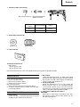
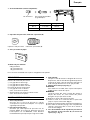
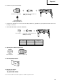
4. Bolt placing operation with Chemical Anchor. (rotation + hammering)
(SDS-plus shank)
12.7 mm Chemical Anchor Adapter
19 mm Chemical Anchor Adapter
Standard socket
on the market
5. Drilling holes and driving screws (rotation only)
䡬 Drill chuck, chuck adapter (G), special screw and chuck wrench
Chuck adapter (G)
(SDS-plus shank)
Chuck wrench
Drill chuck (13VLRB-D)Special screw
( )
6. Drilling holes (rotation only)
Chuck adapter (D)
(SDS-plus shank)
Chuck wrench
Drill chuck (13VLD-D)
䡬 13 mm drill chuck ass’y (includes chuck wrench) and chuck (for drilling in steel or wood).

English
10
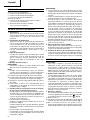
Chuck adapter (D)
(SDS-plus shank)
Bit No. Screw Size Length
No. 2 3 – 5 mm 25 mm
No. 3 6 – 8 mm 25 mm
8. Dust cup, Dust collector (B)
9. Paper dust bag
10. Hammer grease A
500 g (in a can)
70 g (in a green tube)
30 g (in a green tube)
Optional accessories are subject to change without notice.
Dust cup
Dust collector (B)
Bit No.
7. Driving Screws (rotation only)
APPLICATIONS
Rotation and hammering function
䡬 Drilling anchor holes
䡬 Drilling holes in concrete
䡬 Drilling holes in tile
Rotation only function
䡬 Drilling in steel or wood
(with optional accessories)
䡬 Tightening machine screws, wood screws
(with optional accessories)
PRIOR TO OPERATION
1. Power source
Ensure that the power source to be utilized conforms
to the power requirements specified on the product
nameplate.
2. Power switch
Ensure that the power switch is in the OFF position. If
the plug is connected to a power receptacle while the
power switch is in the ON position, the power tool
will start operating immediately, which could cause a
serious accident.
3. Extension cord
When the work area is removed from the power
source, use an extension cord of sufficient thickness
and rated capacity. The extension cord should be
kept as short as practicable.
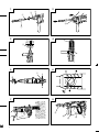
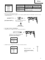
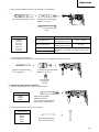
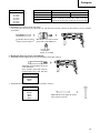
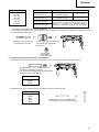
4. Mounting the drill bit (Fig. 1)
CAUTION:
To prevent accidents, make sure to turn the switch
off and disconnect the plug from the receptacle.
NOTE:
When using tools such as bull points, drill bits, etc.,
make sure to use the genuine parts designated by
our company.

English
11
(1) Clean the shank portion of the drill bit.
(2) Insert the drill bit in a twisting manner into the tool
holder until it latches itself. (Fig. 1)
(3) Check the latching by pulling on the drill bit.
(4) To remove the drill bit, fully pull the grip in the
direction of the arrow and pull out the drill bit. (Fig. 2)
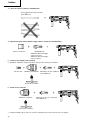
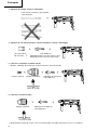
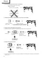
5. Installation of dust cup or dust collector (B)
(Optional accessories) (Fig. 3, Fig. 4)
When using a rotary hammer for upward drilling
operations attach a dust cup or dust collector (B) to
collect dust or particles for easy operation.
䡬 Installing the dust cup
Use the dust cup by attaching to the drill bit as shown
in Fig. 3.
When using a bit which has big diameter, enlarge the
center hole of the dust cup with this rotary hammer.
䡬 Installing dust collector (B)
When using dust collector (B), insert dust collector
(B) from the tip of the bit by aligning it to the groove
on the grip. (Fig. 4)
CAUTION:
䡬 The dust cup and dust collector (B) are for exclusive
use of concrete drilling work. Do not use them for
wood or metal drilling work.
䡬 Insert dust collector (B) completely into the chuck
part of the main unit.
䡬 When turning the rotary hammer on while dust
collector (B) is detached from a concrete surface,
dust collector (B) will rotate together with the drill bit.
Make sure to turn on the switch after pressing the
dust cup on the concrete surface. (When using dust
collector (B) attached to a drill bit that has more than
190 mm of overall length, dust collector (B) cannot
touch the concrete surface and will rotate. Therefore
please use dust collector (B) by attaching to drill bits
which have 166 mm, 160 mm, and 110 mm overall
length.)
䡬 Dump particles after every two or three holes when
drilling.
䡬 Please replace the drill bit after removing dust
collector (B).
6. Selecting the driver bit
Screw heads or bits will be damaged unless a bit
appropriate for the screw diameter is employed to
drive in the screws.
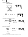
7. Confirm the direction of bit rotation (Fig. 5)
The bit rotates clockwise (viewed from the rear side)
by pushing the R-side of the push button. The L-side
of the push button is pushed to turn the bit
counterclockwise.
HOW TO USE
CAUTION:
To prevent accidents, make sure to turn the switch
off and disconnect the plug from the receptacle when
the drill pits and other various parts are installed or
removed. The power switch should also be turned
off during a work break and after work.
1. Switch operation
The rotation speed of the drill bit can be controlled
steplessly by varying the amount that the trigger
switch is pulled. Speed is low when the trigger switch
is pulled slightly and increases as the switch is pulled
more. Continuous operation may be attained by
pulling the trigger switch and depressing the stopper.
To turn the switch OFF, pull the trigger switch again
to disengage the stopper, and release the trigger
switch to its original position.
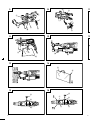
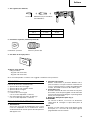
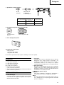
2. Rotation + hammering
This rotary hammer can be set to rotation and
hammering mode by pressing the push button and
turning the change lever to the
mark. (Fig. 6)
(1) Mount the drill bit.
(2) Pull the trigger switch after applying the drill bit tip to
the drilling position. (Fig. 7)
(3) Pushing the rotary hammer forcibly is not necessary
at all. Pushing slightly so that drill dust comes out
gradually is sufficient.
CAUTION:
When the drill bit touches construction iron bar, the
bit will stop immediately and the rotary hammer will
react to revolve. Therefore grip the side handle and
handle tightly as shown in Fig. 7.
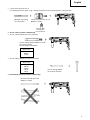
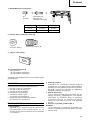
3. Using the dust-collecting adapter and dust bag.
Using this unit with the dust-collecting adapter and
dust bag attached creates a more hygienic working
environment free of flying dust. Attach as shown in
Fig. 8. The unit can be used as an ordinary rotary
hammer when the dust-collecting adapter and dust
bag are not attached.
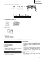
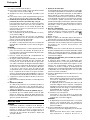
(1) Attaching the dust-collecting adapter and the dust
bag.
a) Attaching the dust-collecting adapter.
Loosen the knob on the side handle and insert the
attachment rod on the dust-collecting adapter in
the mounting hole.
The adapter can be inserted from either direction
A or B (see Fig. 9). Insert and push in the hose in
the hose attachment hole of the main unit until it
reaches the inner surface (depth 15 mm) and
confirm that it is firmly fixed. (see Fig. 10).
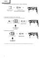
b) Attaching the dust bag.
Insert the dust bag firmly in the dust bag
attachment hole on the main unit and fasten
securely (see Fig. 11).
CAUTION
䡬 The dust-collecting adapter and dust bag is made
for use when drilling concrete. Do not use for
drilling holes in metal or wood.
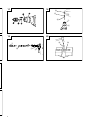
(2) Adjusting the dust-collecting adapter.
a) Adjusting the position of the dust-collecting
adapter.
After firmly inserting the drill bit, loosen the wing
bolt and drill bit tip and the end of the dust-
collecting adapter in contact with each other (see
Fig. 12).
b) Setting the hole-drilling depth.
Move the stopper to determine the stroke. The
stroke is the hole-drilling depth (see Fig. 12).
䡬 The maximum hole-drilling depth when using the
dust-collecting adapter is 100 mm.
䡬 It is possible when using the dust-collecting
adapter to use HITACHI drill bits up to a overall
length of 216 mm. A hole-drilling depth of 45 mm
will allow dust-collecting when the overall length
of the drill bit is 116 mm.
(3) Drilling holes
When drilling holes, secure the main unit so that the
end of the dust-collecting adapter contacts with the
concrete surface perfectly during drilling. Dust-
collecting effectiveness is reduced if the adapter is
not in contact with the surface (see Fig. 13).

English
12
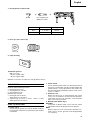
(4) Removing dust
Excessive dust in the dust bag will reduce dust-
collecting effectiveness. Remove dust from the dust
bag regularly.
Remove the dust bag from the main unit, pull out the
rail and throw away the dust and clean (see Fig. 14).
4. When not using the dust-collecting adapter
When removing the dust-collecting adapter and the
dust bag to use as a normal rotary hammer, insert
the provided cap in the hose attachment hole. (see
Fig. 15). After removing the dust bag, the air blowing
out from the attachment hole is reduced and no air
will blow onto your face.
5. Rotation only
Remove the dust-collecting adapter as it cannot be
used. Insert the provided cap in the hose attachment
hole.
This rotary hammer can be set to rotation only mode
by pressing the push button and turning the change
lever to the
mark. (Fig. 16)
To drill wood or metal material using the drill chuck
and chuck adapter (optional accessories), proceed as
follows.
Installing drill chuck and chuck adapter: (Fig. 17)
(1) Attach the drill chuck to the chuck adapter.
(2) The part of the SDS-plus shank is the same as the
drill bit. Therefore, refer to the item of “Mounting the
drill bit” for attaching it.
CAUTION:
䡬 Application of force more than necessary will not
only expedite the work, but will deteriorate the tip
edge of the drill bit and reduce the service life of the
rotary hammer in addition.
䡬 Drill bits may snap off while withdrawing the rotary
hammer from the drilled hole. For withdrawing, it is
important to use a pushing motion.
䡬 Do not attempt to drill anchor holes or holes in
concrete with the machine set in the rotation only
function.
䡬 Do not attempt to use the rotary hammer in the
rotation and striking function with the drill chuck and
chuck adapter attached. This would seriously shorten
the service life of every component of the machine.
6. When driving machine screws (Fig. 18)
First, insert the bit into the socket in the end of chuck
adapter (D).
Next, mount chuck adapter (D) on the main unit
using procedures described in 4 (1), (2), (3), put the
tip of the bit in the slots in the head of the screw,
grasp the main unit and tighten the screw.
CAUTION:
䡬 Exercise care not to excessively prolong driving time,
otherwise, the screws may be damaged by excessive
force.
䡬 Apply the rotary hammer perpendicularly to the screw
head when driving the screw; otherwise, the screw
head or bit will be damaged, or driving force will not
be fully transferred to the screw.
䡬 Do not attempt to use the rotary hammer in the
rotation and striking function with the chuck adapter
and bit attached.
7. When driving wood screws (Fig. 18)
(1) Selecting a suitable driver bit
Employ plus-head screws, if possible, since the driver
bit easily slips off the heads of minus-head screws.
(2) Driving in wood screws
䡬 Prior to driving in wood screws, make pilot holes
suitable for them in the wooden board. Apply the bit
to the screw head grooves and gently drive the screws
into the holes.
䡬 After rotating the rotary hammer at low speed for a
while until the wood screw is partly driven into the
wood, squeeze the trigger more strongly to obtain
the optimum driving force.
CAUTION:
Exercise care in preparing a pilot hole suitable for the
wood screw taking the hardness of the wood into
consideration. Should the hole be excessively small
or shallow, requiring much power to drive the screw
into it, the thread of the wood screw may sometimes
be damaged.
8. How to use the drill bit (taper shank) and the taper
shank adapter
(1) Mount the taper shank adapter to the rotary hammer.
(Fig. 19)
(2) Mount the drill bit (taper shank) to the taper shank
adapter. (Fig. 19)
(3) Turn the switch ON, and drill a hole in prescribed
depth.
(4) To remove the drill bit (taper shank), insert the cotter
into the slot of the taper shank adapter and strike the
head of the cotter with a hammer supporting on a
rests. (Fig. 20)
LUBRICATION
Low viscosity grease is applied to this rotary hammer so
that it can be used for a long period without replacing
the grease. Please contact the nearest service center for
grease replacement when any grease is leaking form
loosened screw.
Further use of the rotary hammer with lock off grease
will cause the machine to seize up reduce the service life.
CAUTION:
A special grease is used with this machine, therefore,
the normal performance of the machine may be badly
affected by use of other grease. Please be sure to let
one of our service agents undertake replacement of
the grease.
MAINTENANCE AND INSPECTION
1. Inspecting the drill bits
Since use of a dull tool will cause motor
malfunctioning and degraded efficiency, replace the
drill bit with new ones or resharpen them without
delay when abrasion is noted.
2. Inspecting the mounting screws
Regularly inspect all mounting screws and ensure
that they are properly tightened. Should any of the
screws be loose, retighten them immediately. Failure
to do so could result in serious hazard.
3. Maintenance of the motor
The motor unit winding is the very ”heart” of the
power tool. Exercise due care to ensure the winding
does not become damaged and/or wet with oil or
water.

English
13
4. Inspecting the carbon brushes
For your continued safety and electrical shock
protection, carbon brush inspection and replacement
on this tool should ONLY be performed by a Hitachi
Authorized Service Center.
5. Replacing supply cord
If the supply cord of Tool is damaged, the Tool must
be returned to Hitachi Authorized Service Center for
the cord to be replaced.
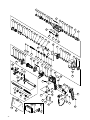
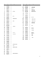
6. Service parts list
A: Item No.
B: Code No.
C: No. Used
D: Remarks
CAUTION:
Repair, modification and inspection of Hitachi Power
Tools must be carried out by a Hitachi Authorized
Service Center.
This Parts List will be helpful if presented with the
tool to the Hitachi Authorized Service Center when
requesting repair or other maintenance.
In the operation and maintenance of power tools, the
safety regulations and standards prescribed in each
country must be observed.
MODIFICATION:
Hitachi Power Tools are constantly being improved
and modified to incorporate the latest technological
advancements.
Accordingly, some parts (i.e. code numbers and/or
design) may be changed without prior notice.
NOTE:
Due to HITACHI’s continuing program of research and
development, the specifications herein are subject to
change without prior notice.
IMPORTANT:
Correct connection of the plug
The wires of the mains lead are coloured in accordance
with the following code:
Blue: -Neutral
Brown: -Live
As the colours of the wires in the mains lead of this tool
may not correspond with the coloured markings
identifying the terminals in your plug proceed as follows:
The wire coloured blue must be connected to the terminal
marked with the letter N or coloured black. The wire
coloured brown must be connected to the terminal
marked with the letter L or coloured red. Neither core
must be connected to the earth terminal.
NOTE:
This requirement is provided according to BRITISH
STANDARD 2769: 1984.
Therefore, the letter code and colour code may not be
applicable to other markets except The United Kingdom.
Information concerning airborne noise and vibration
The measured values were determined according to
EN60745.
The typical A-weighted sound pressure level: 90 dB (A).
The typical A-weighted sound power level: 103 dB (A).
Wear ear protection.
The typical weighted root mean square acceleration
value: 8.6 m/s
2
.

Deutsch
14
ALLGEMEINE VORSICHTSMASSNAHMEN
WARNUNG! Bei der Verwendung von Elektrowerkzeugen
müssen immer die grundlegenden Vorsichtsmaßnahmen
befolgt werden, um das Risiko von Feuer, elektrischem
Schlag und persönlicher Verletzung und den
nachfolgenden Punkten zu vermeiden.
Lesen Sie diese Anweisungen völlig, bevor Sie dieses
Erzeugnis verwenden, und bewahren Sie diese
Anweisungen auf.
Für sicheren Betrieb:
1. Der Arbeitsplatz sollte sauber gehalten werden.
Unaufgeräumte Arbeitsplätze und Werkbänke
erhöhen die Unfallgefahr.
2. Die Betriebsbedingungen beachten. Elektrowerkzeuge
sollten nicht dem Regen ausgesetzt werden. Ebenfalls
sollten Sie nicht an feuchten oder nassen Plätzen
gebraucht werden. Der Arbeitsplatz sollte gut
beleuchtet sein.
Verwenden Sie Elektrowerkzeuge nicht an Orten,
an denen die Gefahr von Feuer oder Explosion
besteht.
3. Schutzmaß nahmen gegen elektrische Schläge
treffen. Darauf achten, daß das Gehäuse nicht in
Kontakt mit geerdeten Flachen kommt (z.B. Rohre,
Radiatoren, Elektroherde, Kühlschränke).
4. Kinder und gebrechliche Personen sollten vom Gerät
ferngehalten werden. Andere Personen nicht mit
dem Werkzeug oder dem Verlängerungskabel in
Kontakt kommen lassen. Besucher sollten vom
Arbeitsbereich ferngehalten werden.
5. Nicht benutzte Werkzeuge sollten sicher aufbewahrt
werden. Sie sollten an einem trockenen und
hochgelegenen oder verschließbaren Ort
aufbewahrt werden, außerhalb der Reichweite von
Kindern und gebrechlichen Personen.
6. Werkzeuge sollten nicht mit übermäßiger Gewalt
verwendet werden. Ihre Leistung ist besser und
sicherer, wenn sie mit der vorgeschriebenen
Geschwindigkeit verwendet werden.
7. Nur die korrekten Werkzeuge verwenden. Niemals
ein kleineres Werkzeug oder Zusatzgerat für
Arbeiten verwenden, die Hochleistungsgerate
erfordern. Nur Werkzeuge verwenden, die dem
Verwendungszweck entsprechen, d.h. niemals eine
Kreissäge zum Sägen von Ästen oder
Baumstämmen verwenden.
8. Die richtige Kleidung tragen. Keine lose Kleidung
oder Schmuck tragen, da sich lose Kleidungsstücke
in den bewegenden Teilen verfangen können. Bei
Arbeiten im Freien sollten Gummihandschuhe und
rutschfeste Schuhe getragen werden. Tragen Sie
eine schützende Haarabdeckung, um langes Haar
zurückzuhalten.
9. Es sollte eine Sicherheitsbrille getragen werden.
Bei Arbeiten mit Staubentwicklung sollte eine
Gesichtsoder Staubmaske getragen werden.
10. Schließen Sie eine Staubabsaugvorrichtung an.
Wenn Vorrichtungen für den Anschluß von
Staubabsaug- und -sammelvorrichtungen
vorhanden sind, so stellen Sie sicher, daß diese
angeschlossen sind und richtig verwendet werden.
11. Niemals das Kabel mißbrauchen. Ein Werkzeug
niemals am Kabel tragen oder bei Abtrennung von
der Steckdose das Kabel harausreißen. Das Kabel
sollte gegen Hitze, Öl und scharfe Kanten geschützt
werden.
12. Den Arbeitsplatz gut absichern. Zwingen oder einen
Schraubstock zur Befestigung des Werkstücks
verwenden. Das ist sicherer als die Benutzung der
Hände und macht beide Hände zur Bedienung des
Werkzeugs frei.
13. Sich niemals weit überbeugen. Immer einen festen
Stand und ein sicheres Gleichgewicht bewahren.
14. Die Werkzeuge sollten sorgfältig behandelt werden.
Für einen einwandfreien und sicheren Betrieb sollten
sie stets scharf sein und saubergehalten werden.
Die Anleitungen für schmierung und Austausch des
Zuehörs unbedingt einhalten. Die Kabel der Geräte
regelmäßig überprüfen und bei Beschädigung durch
eine autorisierte Kundendienststelle reparieren
lassen. Ebenfalls die Verlägerungskabel regelmäßig
überprüfen und bei Beschadigung auswechseln. Die
Handgriffe sollten stets trocken und sauber sein,
sowie keine Öl- oder Schmierfett stellen aufweisen.
15. Werkzeuge vom Netz trennen, wenn sie nicht
benutzt werden, vor Wartungsarbeiten und beim
Austausch von Zubehörteilen wie z.B. Blätter, Bohrer
und Messer.
16. Alle Stellkeile und Schraubenschlüssel entfernen.
Vor Einschaltung des Gerätes darauf achten, daß
alle Stellkeile und Schraubenschlüssel entfernt
worden sind.
17. Ein unbeabsichtigtes Einschalten sollte vermieden
werden. Niemals ein angeschlossenes Werkzeug
mit dem Finger am Schalter tragen. Vor Anschluß
überprüfen, ob das Gerät ausgeschaltet ist.
18. Im Freien ein Verlängerungskabel verwenden. Nur
ein Verlängerungskabel verwenden, das für die
Verwendung im Freien markiert ist.
19. Den Arbeitsvorgang immer unter Kontrolle haben.
Das Gerät niemals in einem abgespannten Zustand
verwenden.
20. Beschädigte Teile überprüfen. Vor Benutzung des
Werkzeugs sollten beschädigte Teile oder
Schutzvorrichtungen sorgfältig überprüft werden,
um festzustellen, ob sie einwandfrei funktionieren
und die vorgesehene Funktion erfüllen, Ausrichtung,
Verbindungen sowie Anbringung sich bewegender
Teile überprüfen. Ebenfalls uberprufen, ob Teile
gebrochen sind. Teile oder Schutzvorrichtungen,
die beschädigt sind, sollten, wenn in dieser
Bedienungsanleitung nichts anderes erwähnt ist,
durch eine autorisierte Kundendienststelle ausge
wechselt oder repariert werden. Dasselbe gilt für
defekte Schalter. Wenn sich das Werkzeug nicht
mit dem Schalter einoder ausschalten läßt, sollte
das Werkzeug nicht verwendet werden.
21. Warnung
Die Verwendung von anderem Zubehör oder
anderen Zusätzen als in dieser Bedienungsanleitung
empfohlen kann das Risiko einer Körperverletzung
einschließen.
22. Lassen Sie Ihr Werkzeug durch qualifiziertes Personal
reparieren.
Dieses Elektrowerkzeug entspricht den zutreffenden
Sicherheitsanforderungen. Reparaturen sollten nur
von qualifiziertem Personal unter Verwendung von
Originalersatzteilen durchgeführt werden, da sonst
beträchtliche Gefahr für den Benutzer auftreten kann.

Deutsch
15
TECHNISCHE DATEN
Spannung (je nach Gebiet)* (110V, 230V)
Leistungsaufnahme 720W*
Leerlaufdrehzahl 0 – 1050
min
–1
Vollastschlagzahl 0 – 4600 min
–1
Kapazität: Beton 3,4 – 24 mm
Stahl 13 mm
Holz 32 mm
Gewicht (ohne Kabel und Handgriff) 2,8 kg
Staubfangadapter
Max. Lochbohrtiefe: 100 mm (zwischen 0 und 100 mm verstellber)
Bohrerdurch messer: 3,4 – 24 mm
Max. Länge der Bohrspitze: 270 mm
(Gesamtlänge)
Staubbeutelfassungsvermögen 0,4 Liter
* Vergessen Sie nicht, die Produktangaben auf dem Typenschild zu überprüfen, da sich diese je nach Verkaufsgebiet
ändern.
VORSICHTSMASSNAHMEN BEI BENUTZUNG
DES BOHRHAMMERS
1. Ohrenstöpsel zum Schutz der Ohren während des
Betriebs tragen.
2. Die Bohrerspitze während oder unmittelbar nach dem
Betrieb nicht berühren. Die Bohrerspitze wird während
des Betriebs sehr heiß, sobaß es zu ernsthaften
Verbrennungen führen könnte.
3. Bevor man on der Wand, im Boden oder an der
Decke etwas ausbricht, meißelt oder bohrt, muß man
sich sorgfältig davon überzeugen, ob keine
elektrischen Kabel oder Kabelrohre darunter liegen.
4. Immer den körper-Handgriff und Seiten-Handgriff des
Elektrowerkzeugs festhalten, weil die entstehende
Gegenkraft sonst zu einem ungenauen und
gefährlichen Arbeiten führt.
STANDARDZUBEHÖR
(1) Tasche (Plastk) ............................................................ 1
(2) Handgriff ..................................................................... 1
(3) Staubfangadapter ....................................................... 1
(4) Staubsak ...................................................................... 1
[Nummer (3) und (4) beziehen sich auf die Verwendung
Beton.]
(5) Kappe .......................................................................... 1
Das Standardzubehör kann ohne vorherige
Bekanntmachung jederzeit geändert werden.
SONDERZUBEHÖR (separat zu beziehen)
1. Bohren von Ankerlöchern (Drehen und Hämmern)
䡬 Bohrer (dünner Schaft)
Adapter für dünnen Schaft
(SDS-Plus Schaft)
Bohrer (dünner Shaft)
Bohrer (dünner Schaft)
Außendurchmesser Arbeitslänge Gesamtlänge
3,4 mm
45 mm 90 mm
3,5 mm

Deutsch
16
Konusschaftadapter Anwendbarer Bohrer
Morsekonus (Nr.1) Bohrer (Konusschaft) 11,0 ~ 17,5 mm
Morsekonus (Nr.2) Bohrer (Konusschaft) 21,5 mm
A-Konus Der Konusschaftadapter in der Form des A- oder
B-Konus wird nach Wunsch geliefert, doch ist
B-Konus der passende Bohrer separat zu beziehen.
Bohrer (Kegelschaft)
Konusschaftadapter
(SDS-Plus Schaft)
Dorn
䡬 Bohrer (Kegelschaft) und Konusschaftadapter
䡬 13 mm Bohrhammerfutter
Zum Bohrbetrieb mit gerader Schlagspitze für schlagbohrer mit bohrhammer.
13 mm Bohrhammerfutter
(SDS-Plus Schaft)
Gerade Meißelspitze
(
für Schlagbohrer
)
Außendurchmesser
11,0 mm
12,3 mm
12,7 mm
14,3 mm
14,5 mm
17,5 mm
21,5 mm
Bohrfutterschlüssel
2. Ankereinsatz (Drehen und Hämmern)
䡬 Adapter für Ankerbefestigung (mit Bohrhammer)
Adapter für Ankerbefestigung (SDS-Plus Schaft)
(mit Bohrhammer)
Gesamtlänge: 160, 260 mm
Ankergröße
W1/4”
W5/16”
W3/8”
䡬 Adapter für Ankerbefestigung (mit dem Handhammer)
Adapter für Ankerbefestigung
(mit dem Handhammer)
Ankergröße
W1/4”
W5/16”
W3/8”
W1/2”
W5/8”

Deutsch
17
3. Aufbrecharbeiten (Drehen und Hämmern)
Spitzmeißel (Nur runder Typ)
(SDS-Plus Schaft)
4. Bolzenplazierung für Chemical Anchor (Drehen und Hämmern)
(SDS-Plus Schaft)
12,7 mm Adapter für Chemical Anchor
19 mm Adapter für Chemical Anchor
Sockel auf
markierter stelle
( )
6. Löcherbohren (nur Drehung)
Bohrfutteradapter (D)
(SDS-Plus Schaft)
Bohrfutterschlüssel
Bohrfutter (13VLD-D)
5. Löcherbohren und schneidschraube (nur Drehung)
䡬 Bohrfutter, Bohrfutteradapter (G), Spezialschraube und Bohrfutterschlüssel
Spezialschraube
Bohrfuter (13VLRB-D)
Bohrfutteradapter (G)
(SDS-Plus Schaft)
Bohrffutterschlüssel
䡬 Zum Bohren von Stahl oder Holz: Bohrfuttervorrichtung von 13 mm (einschl Futterschlüssel), Futteradapter.

Deutsch
18
Bohrfutteradapter (D)
(SDS-Plus Schaft)
Bohrerspitzen-
Schraubengröße Länge
nummer
Nr. 2 3 - 5 mm 25 mm
Nr. 3 6 - 8 mm 25 mm
8. Staubschale, Staubfang (B)
9. Papierstaubtüte
10. Hammer Schmierfett A
500 g (Dose)
70 g (in grüner Tube)
30 g (in grüner Tube)
Das Sonderzubehöre kann ohne vorherige Bekanntmachung jederzeit geändert werden.
Bohrespitzennummer
Staubfang (B)
Staubschale
7. Schneidschraube (nur Drehung)
ANWENDUNGEN
Dreh- und Hämmerfunktion
䡬 Bohren von Ankerlöchern
䡬 Bohren von Löchern in Beton
䡬 Bohren von Löchern in Kachel
Nur Drehbohrfunktion
䡬 Bohren in Stahl oder Holz (mit Sonderzubehör)
䡬 Anziehen von Maschinenschrauben, Holzschrauben
(mit Sonderzubehör)
VOR INBETRIEBNAHME
1. Netzspannung
Prüfen, daß die zu verwendende Netzspannung der
Angabe auf dem Typenschild entspricht.
2. Netzschalter
Prüfen, daß der Nezschalter auf „AUS” steht. Wenn
der Stecker an das Netz angeschlossen wird, während
der Schalter auf „EIN” steht, beginnt das Werkzeug
sofort zu laufen, was gefährlich ist.
3. Verlängerungskabel
Wenn der Arbeitsbereich nicht in der Nähe des
Netzanschlusses liegt, ist ein Verlängerungskabel
ausreichenden Querschnitts und ausreichender
Nennleistung zu verwenden. Das Verlängerungskabel
sollte so kurz wie möglich gehalten werden.
4. Anbringen des Bohreinsatzes (Abb. 1)
ACHTUNG:
Stellen Sie zur Verhütung von Unfällen sicher, dass
der Schalter ausgeschaltet und der Stecker aus der
Steckdose gezogen ist.

Deutsch
19
HINWEIS:
Achten Sie bei der Verwendung von Werkzeugen wie
Meißeln, Bohrern usw. darauf, von unserer Firma
bezeichnete Markenteile zu verwenden.
(1) Reinigen Sie den Schaftabschnitt des Bohrers.
(2) Schieben Sie den Bohrer unter Drehung in den
Werkzeughalter ein, bis er sich verriegelt. (Abb. 1)
(3) Überprüfen Sie die Verriegelung durch Ziehen am
Bohrer.
(4) Zum Entfernen des Bohrers den Griff in Pfeilrichtung
ziehen, und den Bohrer herausziehen. (Abb. 2)
5. Beim Installieren der Staubschale oder des
Staubfangs (B) (Zonderzubehör) (Abb. 3, Abb. 4)
Wenn ein Bohrhammer zum Bohren nach oben ohne
Staubfangadapter verwendet wird, eine Staubkappe
oder einen Staubfang (B) zum Auffangen von Staub
und Partikeln zum leichten Betrieb anbringen.
䡬 Anbringen der Staubschale
Die Staubschale durch Anbringen an die Bohrspitze
wie in Abb. 3 gezeigt verwenden.
Bei Bohrspitzen mit großem Durchmesser das
Mittenloch der Staubschale mit diesem Bohrhammer
vergrößern.
䡬 Anbringen des Staubfangs (B)
Bei Verwendung des Staubfangs (B) den Staubfang
(B) von der Spitze der Bohrspitze einführen, und an
die Rille an der Spitze ansetzen. (Abb. 4)
ACHTUNG:
䡬 Die Staubschale und der Staubfang (B) sind nur für
Bohren in Beton gedacht. Nicht für Bohrarbeiten in
Holz oder Metall verwenden.
䡬 Den Staubfang (B) vollständig in den Futterteil der
Haupteinheit einsetzen.
䡬 Wenn am Bohrhammer gedreht wird, während die
Staubfang (B) von der Betonoberfläche abgenommen
ist, dreht sich die Staubfang (B) zusammen mit der
Bohrspitze. Immer am Schalter drehen, nachdem die
Staubschale auf die Betonoberfläche gedrückt ist.
(Bei Verwendung der Staubfang (B) durch Anbringen
einer Bohrspitze mit mehr als 190 mm Gesamtlänge
kann die Staubfang (B) nicht die Betonoberfläche
berühren und dreht sich. Darum immer Bohrspitzen
mit 166, 160 und 110 mm Gesamtlänge verwenden.)
䡬 Nach dem Bohren von zwei oder drei Löchern den
Inhalt der Staubfang (B) ausleeren.
䡬 Die Bohrspitze nach dem Abnehmen der Staubfang
(B) austauschen.
6. Wahl der Schrauberspitze
Falls die Schrauberspitze dem Schraubendurchschnitt
nicht anpassend wird, werden Schraubenkopf und
Schrauberspitze beschädigt.
7. Die Drehrichtung der Bohrerspitze prüfen (Abb. 5)
Die Bohrerspitze dreht sich (von hinten betrachtet)
im Uhrzeigersinn, wenn Sie auf die R-Seite des
Druckschalters drücken.
Um die Bohrerspitze gegen den Uhrzeigersinn zu
drehen, drücken Sie auf die L-Seite des Druckschalters.
GEBRAUCHSANWEISUNG
ACHTUNG:
Zur Verhütung von Unfällen beim Anbringen und
Entfernen von Bohrern und anderen Teilen immer
den Schalter ausschalten und den Stecker des
Netzkabels aus der Steckdose ziehen. Der Schalter
sollte auch während Arbeitsunterbrechungen und
nach der Arbeit ausgeschaltet werden.
1. Betätigung des Schalters
Die Drehzahl des Bohrers kann durch Veränderung
des Drucks auf den Drückerschalter gesteuert werden.
Die Geschwindigkeit ist gering, wenn der
Drückerschalter nur leicht gezogen ist und erhöht
sich, wenn der Schalter weiter durchgezogen wird.
Kontinuierlicher Betrieb läßt sich durch das Ziehen
des Drückerschalters und Eindrücken des
Arretierknopfes erreichen. Zum Ausschalten wird der
Drückerschalter erneut gezogen und der Arretierknopf
gelöst. Nach dem Loslassen kehrt der Drückerschalter
in seine ursprüngliche Stellung zurück.
2. Drehen und Hämmern
Dieser Bohrhammer kann durch Druck auf den
Druckknopf und Drehen des Umschalthebels zur
Markierung
auf Bohr- und Hammerbetrieb
eingestellt werden. (Abb. 6)
(1) Die Bohrerspitze anbringen.
(2) Den Triggerschalter nach Anbringen in Bohrlage der
Bohrerspitze ziehen. (Abb. 7)
(3) Es ist nicht nötig den Bohrhammer stark anzudrücken.
Leichtes Andrücken, so daß der Bohrstaub regelmäßig
herausfällt, ist gerade genügend.
ACHTUNG:
Wenn der Bohrer mit Baueisenstangen in Berührung
kommt, stoppt sofort der Bohren, und nur der
Bohrhammer dreht sich. Deshalb den Handgriff gut
fest halten wie in Abb. 7 gezeigt.
3. Verwendung des Staubfangadapters und Staubsacks
Der Einsatz der Maschine mit Staubfangadapter und
Staubsack sorgt für eine sauberere Arbeitsumgebung,
frei von herumwirbelndem Staub. Befestigen Sie den
Staubfangbeutel wie in Abb. 8 gezeigt. Ohne
Staubfangadapter und Staubsack das Gerät als
normale Schlagbohrmaschine verwendet werden.
(1) Befestigung des Staubfangadapters und des
Staubsacks.
a) Befestigung des Staubfangadapters
Lösen Sie die Knopf am Seitenbohrer, und stecken
Sie den Befestigungsstab in das Befestigungsloch
des Staubfangadapters.
Der Adapter kann sowohl von Richtung A als auch
B (siehe Abb. 9) eingesteckt werden. Den Schlauch
in das Schlauchbefestigungsloch des Hauptgeräts
drücken, bis er die Innenfläche (Tiefe 15 mm)
erreicht und bestätigen, daß er fest sitzt (siehe
Abb. 10).
b) Ansetzen des Staubsacks
Stecken Sie den Staubsack fest in das
Befestigungsloch an der Bohrmaschine ein, und
befestigen Sie ihn (siehe Abb. 11).
VORSICHT
䡬 Der staubfangadapter und Staubsack ist für die
Verwendung beim Bohren von beton vorgesehen.
Verwenden Sie diesen deshalb nicht beim Bohren
Metall oder Holz.
(2) Einstellung des Staubfangadapters
a) Einstellung der Position des Staubfangadapters
Lösen Sie, nachdem Sie den Bohrer fest
eingesteckt haben, die Spannfutterschraube und
die Bohrerspitze und das Ende des
staubfangadapters, die sich einander berühren
(siehe Abb. 12).
b) Einstellung der Lochbohrtiefe
Versetzen Sie den Anschlag zur Festlegung des
Hubs. Der Hub ist die Lochbohrtiefe (siehe
Abb. 12).
Seite laden ...
Seite laden ...
Seite laden ...
Seite laden ...
Seite laden ...
Seite laden ...
Seite laden ...
Seite laden ...
Seite laden ...
Seite laden ...
Seite laden ...
Seite laden ...
Seite laden ...
Seite laden ...
Seite laden ...
Seite laden ...
Seite laden ...
Seite laden ...
Seite laden ...
Seite laden ...
Seite laden ...
Seite laden ...
Seite laden ...
Seite laden ...
Seite laden ...
Seite laden ...
Seite laden ...
Seite laden ...
Seite laden ...
Seite laden ...
Seite laden ...
Seite laden ...
Seite laden ...
Seite laden ...
Seite laden ...
Seite laden ...
Seite laden ...
Seite laden ...
Seite laden ...
Seite laden ...
Seite laden ...
Seite laden ...
Seite laden ...
Seite laden ...
Seite laden ...
Seite laden ...
Seite laden ...
Seite laden ...
Seite laden ...
Seite laden ...
Seite laden ...
Seite laden ...
Seite laden ...
Seite laden ...
Seite laden ...
Seite laden ...
Seite laden ...
Seite laden ...
-
 1
1
-
 2
2
-
 3
3
-
 4
4
-
 5
5
-
 6
6
-
 7
7
-
 8
8
-
 9
9
-
 10
10
-
 11
11
-
 12
12
-
 13
13
-
 14
14
-
 15
15
-
 16
16
-
 17
17
-
 18
18
-
 19
19
-
 20
20
-
 21
21
-
 22
22
-
 23
23
-
 24
24
-
 25
25
-
 26
26
-
 27
27
-
 28
28
-
 29
29
-
 30
30
-
 31
31
-
 32
32
-
 33
33
-
 34
34
-
 35
35
-
 36
36
-
 37
37
-
 38
38
-
 39
39
-
 40
40
-
 41
41
-
 42
42
-
 43
43
-
 44
44
-
 45
45
-
 46
46
-
 47
47
-
 48
48
-
 49
49
-
 50
50
-
 51
51
-
 52
52
-
 53
53
-
 54
54
-
 55
55
-
 56
56
-
 57
57
-
 58
58
-
 59
59
-
 60
60
-
 61
61
-
 62
62
-
 63
63
-
 64
64
-
 65
65
-
 66
66
-
 67
67
-
 68
68
-
 69
69
-
 70
70
-
 71
71
-
 72
72
-
 73
73
-
 74
74
-
 75
75
-
 76
76
-
 77
77
-
 78
78


Hitachi DH 24PD2 Handling Instructions Manual
- Kategorie
- Elektrowerkzeuge
- Typ
- Handling Instructions Manual
in anderen Sprachen
- English: Hitachi DH 24PD2
- français: Hitachi DH 24PD2
- español: Hitachi DH 24PD2
- italiano: Hitachi DH 24PD2
- Nederlands: Hitachi DH 24PD2
- português: Hitachi DH 24PD2
Verwandte Papiere
-
Hitachi dh24pd3 Benutzerhandbuch
-
Hitachi DH 28PBY Handling Instructions Manual
-
-
-
-
-
-
-
Hitachi DH22PG Bedienungsanleitung
-