
CheetahSwitch Workgroup-3008A
CheetahSwitch Workgroup-3016A
Quick Installation Guide


Quick Installation Guide
CheetahSwitch Workgroup-3008A
Smart Fast Ethernet Switch with 8 10BASE-T / 100BASE-TX Ports
CheetahSwitch Workgroup-3016A
Smart Fast Ethernet Switch with 16 10BASE-T / 100BASE-TX Ports

Copyright © 2000 by Accton Technology Corporation. All rights reserved.
No part of this document may be copied or reproduced in any form or by any means without the prior
written consent of Accton Technology Corporation.
Accton makes no warranties with respect to this documentation and disclaims any implied warranties
of merchantability, quality, or fitness for any particular purpose. The information in this document is
subject to change without notice. Accton reserves the right to make revisions to this publication
without obligation to notify any person or entity of any such changes.
International Headquarters USA Headquarters
No. 1 Creation Road III, 6 Hughes
Science-based Industrial Park Irvine, CA 92618
Hsinchu 300, Taiwan, R.O.C. Phone Numbers -
Phone: 886-3-5770-270 Sales: 800-926-9288
FAX: 886-3-5770-267 Support: 888-398-4101 or 949-707-4847
FAX: 949-707-2460
Accton is a trademark of Accton Technology Corporation. Other trademarks or brand names
mentioned herein are trademarks or registered trademarks of their respective companies.
ES3008A
ES3016A
E012000-R05
150917-101

i
Contents
Introduction 1
Installing the Switch 1
Package Contents 1
Description of Hardware 1
Mounting the Hub 2
Connecting the Switch System 3
Powering On the Switch 4
Verifying Port Status 5
Verifying System Operation 5
Applications 5
Product Specifications 7
Troubleshooting 8
Diagnosing Switch Indicators 8
Power and Cooling Problems 8
Installation 8
Transmission Mode 9
Port and Cable Assignments 9
EMI Certification 10
Safety Compliance 12
Warranty 13

ii

Quick Installation Guide
1
1
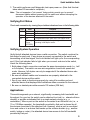
Introduction
These CheetahSwitches are ideal for moving workgroups
from the conventional 10Mbps shared Ethernet collision
domain to multiple dedicated Ethernet segments. These
switches deliver dedicated 10/100 Mbps links to each
attached LAN segment (independent collision domain) or
attached PCs all with conventional cabling and adapters.
They completely eliminate the bottlenecks of shared
10Mbps Ethernet networks by providing a wide bandwidth of up to 3.2 Gbps. This
makes them ideal for increasing the throughput of interconnected Ethernet hubs
or server farms. On top of all that, they use auto-negotiation to select the optimal
transmission speed and communication mode for each connection. They use
store-and-forward switching to maintain maximum data integrity, even under
heavy loading.
Installing the Switch
Before installing the switch, verify that you have all the items listed under
Package Contents. If any of the items are missing or damaged, contact your
local Accton distributor. Also be sure you have all the necessary tools and
cabling before installing the switch. Note that this switch can be installed on any
suitably large flat surface or in a standard EIA 19-inch rack.
Package Contents
These CheetahSwitches include:
CheetahSwitch Workgroup-3008A (Model No. ES3008A), or
CheetahSwitch Workgroup-3016A (Model No. ES3016A)
Four rubber foot pads Quick Installation Guide
AC power cord Owner registration card
Rack mount bracket kit (for ES3016A)
Description of Hardware
These switches contain 8/16 10BASE-T / 100BASE-TX dual-speed ports. They
use auto-negotiation to set the transmission speed (10/100 Mbps) and mode
(half/full duplex). If the attached device does not support auto-negotiation, the
speed will still be correctly set by the switch using auto-sensing. However, full
duplex can only be supported if the attached device also uses auto-negotiation.

CheetahSwitch Workgroup-3008A/3016A
2
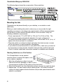
The following figure shows the components of these switches:
Mounting the Hub
This switch can be placed directly on your desktop, or mounted in a rack
(ES3016A).
Before you start installing the switch, make sure you can provide the right
operating environment, including power requirements, sufficient physical space,
and proximity to other network devices that are to be connected. Verify the
following installation requirements:
Power requirements: 110 to 230 VAC (± 10%) at 47 to 63 Hz (± 3Hz). The
switch's power supply automatically adjusts to the input voltage level.
The switch should be located in a cool dry place, with at least 10 cm. (4 in.) of
space at the front and back for ventilation.
Place the switch out of direct sunlight, and away from heat sources or areas
with a high amount of electromagnetic interference.
If you intend to mount the switch in a rack (ES3016A), make sure you have all
the necessary mounting screws, brackets, bolts and nuts, and the right tools.
Check if network cables and connectors needed for installation are available.
Stacking Switches on a Flat Surface
The CheetahSwitch can be stacked
anywhere there is enough flat space, such
as on a table or desktop.
1. Stick the self-adhesive rubber foot pads
(that come with this package) on each of the 4
concave spaces located on the bottom of the first switch.
2. Place the first switch on a firm flat surface where you want to install the stack.
3. Repeat step 1 for each switch before stacking them. The rubber foot pads
cushion the switch against shock/vibrations and provide space between each
switch for ventilation.

Quick Installation Guide
3
3
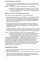
Mounting Switches in a Rack (ES3016A)
Please comply with the following
instructions to ensure that your switch
is securely mounted in the rack.
1. Use a standard EIA 19-inch rack.
2. Use the brackets and screws
supplied in the rack mounting kit.
3. Use a cross-head screwdriver to attach
the brackets to the side of the switch.
4. Position the switch in the rack by lining up the holes in the
brackets with the appropriate holes on the rack, and then use the
supplied screws to mount the switch in the rack.
Connecting the Switch System
These CheetahSwitches have 8/16 RJ-45 ports that support connection to
10Mbps Ethernet or 100Mbps Fast Ethernet, and half or full-duplex operation.
The transmission speed for each port is automatically set by the switch to match
the highest speed supported by the connected device. The transmission mode
can be set for each port using auto-negotiation (if also used by the attached
device). However, full duplex can only be supported if the attached device also
uses auto-negotiation. Also note that this CheetahSwitch uses store-and-forward
switching to maintain maximum data integrity under any type of loading.
Making a Connection to an RJ-45 Port
You can use straight-through twisted-pair cable to connect any RJ-45 (MDI-X)
port on the switch to any device that uses a standard network interface such as a
workstation or server, or to a network interconnection device such as a bridge or
router (depending on the port type implemented).
1. Prepare the network devices you wish to network. Make sure you have
installed 10BASE-T or 100BASE-TX network interface cards for connecting to
the switch's RJ-45 (MDI-X) station ports.
2. Prepare straight-through shielded or unshielded twisted-pair cables with
RJ-45 plugs at both ends. Use 100Ω Category 3, 4 or 5 cable for standard
10Mbps Ethernet connections, or 100Ω Category 5 cable for 100Mbps Fast
Ethernet connections.
3. Connect one end of the cable to the RJ-45 port of the network interface card,
and the other end to any available RJ-45 port on the switch. All RJ-45 ports
support 10Mbps and 100Mbps Ethernet connections. When inserting an
RJ-45 plug, be sure the tab on the plug clicks into position to ensure that it is
properly seated. Using the switch in a stand-alone configuration, you can
network up to 8/16 end nodes.

CheetahSwitch Workgroup-3008A/3016A
4
I Do not plug a phone jack connector into any RJ-45 port. This may damage the
switch. Instead, use only twisted-pair cables with RJ-45 connectors that conform
with FCC standards.
Notes: 1. When using Port 8MDI-X on the ES3008A, do not use Port 8MDI.
2. Make sure each twisted-pair cable does not exceed 100 meters (328 feet).
3. We advise using Category 5 cable for all network connections to avoid
any confusion or inconvenience in the future when you upgrade attached
devices to Fast Ethernet.
Making a Connection via an MDI Daisy-Chain Port
To connect to another compatible switch or hub, take these steps:
1. Use the RJ-45 daisy-chain port (i.e., Port 8MDI on the ES3008A, Port 16MDI
on the ES3016A). When using the ES3016A, set the daisy-chain switch to
MDI and connect to any MDI-X station port on the other device. Alternatively,
you can connect from any RJ-45 MDI-X port on the switch to an MDI daisy-
chain port on the other device.
2. Prepare straight-through shielded or unshielded twisted-pair cables with
RJ-45 plugs at both ends. Use 100Ω Category 3, 4 or 5 cable for standard
10Mbps Ethernet connections, or 100Ω Category 5 cable for 100Mbps Fast
Ethernet connections.
3. Connect one end of the cable to Port 8MDI on the switch, and the other end to
any MDI-X station port on the other device. When inserting an RJ-45 plug, be
sure the tab on the plug clicks into position to ensure that it is properly seated.
Notes: 1. When using Port 8MDI on the ES3008A, do not use Port 8MDI-X.
2. Make sure each twisted-pair cable does not exceed 100 meters (328 feet).
3. To connect to another switch or hub, you may also attach to (MDI-X)
station ports at both ends if you use crossover cabling. (Refer to Port
and Cable Assignments on page 9 for a description of crossover cable.)
Restrictions on Cascade Length - The IEEE 802.3 standard recommends
restricting the number of hubs (i.e., repeaters) cascaded via twisted-pair cable to 4;
while IEEE 802.3u provides even stricter recommendations for Fast Ethernet.
Therefore, when cascading devices other than this switch, please refer to the
accompanying documentation for cascade restrictions. However, note that because
switches break up the path for connected devices into separate collision domains,
you should not include the switch or connected cabling in your calculations for
cascade length involving other devices.
Powering On the Switch
1. Plug the power cord into the power socket at the rear of the switch, and the
other end into a power outlet.
2. Check the LED marked Power on the front panel to see if it is on. The unit will
automatically select the setting that matches the connected input voltage.
Therefore, no additional adjustments are necessary when connecting it to any
input voltage within the range marked on the rear panel.

Quick Installation Guide
5
5
3. The switch performs a self-diagnostic test upon power-on. (Note that this test
takes about 20 seconds to complete.)
Note: The unit supports a "hot remove" feature which permits you to connect/
disconnect cables without powering off the switch and without disrupting the
operation of the devices attached to the switch.
Verifying Port Status
Check each connection by viewing the port status indicators shown in the following table.
DEL etatS noitacidnI
tcA/kniLnO.noitcennockrowtendilavadehsilbatsesahtroP
gnihsalF.tropehtgnisrevartsiciffarT
M001nO.spbM001ottesneebevahsnoitacinummoC
XDFnO.edomxelpud-llufottesneebevahsnoitacinummoC
gnihsalF
neerG
)A8003SE(
nehwtnemgestropehtnoderucconoisillocA
.edomxelpud-flahnignitarepo
Verifying System Operation
Verify that all attached devices have a valid connection. The switch monitors the
link status for each port. If any device is properly connected to the switch and
transmitting a link beat signal, the Link indicator will light up for the corresponding
port. If the Link indicator fails to light when you connect a device to the switch,
check the following items:
Both sides of each connection must use the same transmission mode (i.e., half
or full duplex). The switch can use auto-negotiation to set both speed and
mode. However, full duplex can only be supported if the attached device also
uses auto-negotiation.
Be sure all network cables and connectors are properly attached to the
connected device and the switch.
See if your cable is functioning properly by using it for another port and
attached device that displays valid indications when connected to the network.
Be sure no twisted-pair cable exceeds 100 meters (328 feet).
Applications
This switch segments your network, significantly increasing both bandwidth and
throughput. Any port on the switch can be attached to a hub (i.e., shared collision
domain) or provide a dedicated link to a single network device (e.g., a
workstation). When a port on the switch is connected to an Ethernet hub (i.e., a
10 or 100 Mbps repeater), the bandwidth provided by that port is shared by all
the devices connected to the attached hub. However, when a port is connected
to an end node or to a device that breaks up the collision domain (e.g., another
switch, bridge or router), the attached device has access to the full bandwidth
provided by that port.

CheetahSwitch Workgroup-3008A/3016A
6
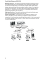
Bridging Functions - This switch provides fully transparent bridging functions
which automatically learn node addresses, that are subsequently used to filter
and forward all traffic based on the destination address. When traffic passes
between devices attached to the same shared collision domain, those packets
are filtered from the switch. But when traffic must be passed between unique
segments (i.e., different ports on the switch), the high-speed switching fabric
forwards the packets at near zero latency.
Switching Functions - This switch uses store-and-forward switching to pass
traffic, thus ensuring data integrity under any load.
Flexible Configuration - This switch is not only designed to segment your
network, but also to provide a wide range of options in setting up network
connections. It can be used as a simple stand-alone switch; or can be connected
with standard repeater hubs, switches, or other network interconnection devices
in various configurations.

Quick Installation Guide
7
7
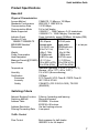
Product Specifications
Base Unit
Physical Characteristics
Access Method CSMA/CD, 10 Mbps or 100 Mbps
Standards Conformance IEEE 802.3, IEEE 802.3u
Communication Rate 10/100 Mbps
Communication Mode Full or half duplex
Media Supported 10BASE-T - 100WCategory 3,4,5 twisted-pair
100BASE-TX - 100WCategory 5 twisted-pair
Indicator Panel Power, link/activity, speed (100 Mbps), full duplex (FDX)
Number of Ports ES3008A ES3016A
10BASE-T/100BASE-TX 8 RJ-45 ports 16 RJ-45 ports
MDI-X/MDI Selection
1
Alternate ports Toggle switch 1: on last port
Dimensions 251x118x37 mm 330x204x44 mm
(9.9x4.7x1.5 in) (13x8x1.7 in)
Weight 0.8Kg (1.76lb) 2.1Kg (4.63lb)
Power Consumption 20 Watts max. 27 Watts max.
Heat Dissipation 68 BTU/hr max. 92 BTU/hr max.
Maximum Current (@110/240V) 0.2 / 0.1 ARMS 0.5 / 0.22 ARMS
Input Power 100 to 240V (±10%), 110 to 230V (±10%),
50 to 60 Hz (±3Hz), 47 to 63 Hz (±3Hz)
Temperature Standard Operating: 0 to 50°C (32 to 122°F)
Storage: -40 to 70°C (-40 to 158°F)
Humidity 5% to 95% (Noncondensing)
Certification CE Mark
Emissions FCC Class B, VCCI Class B, CISPR Class B
Immunity IEC 1000-4-2/3/4/6
Safety CSA/NRTL (C22.2.950,UL1950), TÜV/GS
(EN60950)
Switching Criteria
Network Bridging Function Filtering, forwarding and learning
Switching Method Store-and-forward
Address Table ES3008A: 1K entries
ES3016A: 8K entries
Address Resolution Via fast hashing scheme
Filtering/Forwarding Rate Line speed
Traffic Control
Flow Control Back pressure for half-duplex
IEEE802.3x for full-duplex

CheetahSwitch Workgroup-3008A/3016A
8
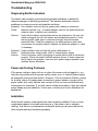
Troubleshooting
Diagnosing Switch Indicators
The switch can be easily monitored through panel indicators to assist the
network manager in identifying problems. This section describes common
problems you may encounter and possible solutions.
Symptom: Link indicator does not light up (green) after making a connection.
Cause: Network interface (e.g., a network adapter card on the attached device),
network cable, or switch port is defective.
Solution: Verify that the switch and attached device are powered on. Be sure the
cable is plugged into both the switch and corresponding device. Verify
that the proper cable type is used and its length does not exceed
specified limits. Check the adapter on the attached device and cable
connections for possible defects. Replace the defective adapter or cable
if necessary.
Symptom: Power indicator does not light up (green) after power on.
Cause: Defective power outlet, power cord, or internal power supply.
Solution: Check the power outlet by plugging in another device that is functioning
properly. Check the power cord with another device. If these measures
fail to resolve the problem, have the unit's power supply replaced by an
qualified Accton distributor.
Power and Cooling Problems
If the power indicator does not turn on when the power cord is plugged in, you
may have a problem with the power outlet, power cord, or internal power supply
as explained in the previous section. However, if the unit powers off after running
for a while, check for loose power connections, power losses or surges at the
power outlet, and verify that the fans on back of the unit are unobstructed and
running prior to shutdown. If you still cannot isolate the problem, then the internal
power supply may be defective. In this case, contact your Accton distributor for
assistance.
Installation
Verify that all system components have been properly installed. If one or more
components appear to be malfunctioning (e.g., the power cord or network
cabling), test them in an alternate environment where you are sure that all the
other components are functioning properly.

Quick Installation Guide
9
9
Transmission Mode
Verify that each port is set to the same transmission mode used by the attached
device (i.e., half or full duplex). All ports can use auto-negotiation to set the
transmission mode. However, full duplex can only be supported if the attached
device also uses auto-negotiation.
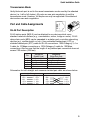
Port and Cable Assignments
RJ-45 Port Description
RJ-45 station ports (MDI-X) can be attached to any devices which use a
standard network interface (e.g., a workstation, server, bridge or router). RJ-45
daisy-chain ports (MDI) can be cascaded to a station port on similar networking
devices (e.g., another switch or hub). Use unshielded twisted-pair (UTP) or
shielded twisted-pair (STP) cable for RJ-45 connections: 100Ω Category 3, 4 or
5 cable for 10 Mbps connections or 100Ω Category 5 cable for 100 Mbps
connections. Also be sure that the length of any twisted-pair connection does not
exceed 100 meters (328 feet).
niP
tnemngissA
)stroPnoitatS(
tnemngissA
)troPniahC-ysiaD(
1+ataDevieceRtupnI+ataDtimsnarTtuptuO
2-ataDevieceRtupnI-ataDtimsnarTtuptuO
3+ataDtimsnarTtuptuO+ataDevieceRtupnI
6-ataDtimsnarTtuptuO-ataDevieceRtupnI
8,7,5,4desUtoNdesUtoN
Schematics for both straight and crossover twisted-pair cable are shown below.
hguorhT-thgiartS revossorC
)buH()retpadA()buH()hctiwS(
+DRI1+DTO1+DRI1+DRI1
-DRI2-DTO2-DRI2-DRI2
+DTO3+DRI3+DTO3+DTO3
-DTO6-DRI6-DTO6-DTO6

CheetahSwitch Workgroup-3008A/3016A
10
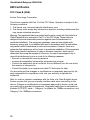
EMI Certification
FCC Class B (USA)
Accton Technology Corporation
This device complies with Part 15 of the FCC Rules. Operation is subject to the
following conditions:
1. This device may not cause harmful interference, and
2. This device must accept any interference received, including interference that
may cause undesired operation.
Warning: This equipment has been tested and found to comply with the limits for a
Class B digital device, pursuant to Part 15 of the FCC Rules. These limits are
designed to provide reasonable protection against harmful interference in a
residential installation. This equipment generates, uses and can radiate radio
frequency energy and, if not installed and used in accordance with the instructions,
may cause harmful interference to radio communications. However, there is no
guarantee that interference will not occur in a particular installation. If this equipment
does cause harmful interference to radio or television reception, which can be
determined by turning the equipment off and on, the user is encouraged to try to
correct the interference by one or more of the following measures:
Reorient or relocate the receiving antenna
Increase the separation between the equipment and receiver
Connect the equipment into an outlet on a circuit different from the one which
the receiver is connected to
Consult the dealer or an experienced radio/TV technician for help
You are cautioned that changes or modifications not expressly approved by the
party responsible for compliance could void your authority to operate the
equipment.
Note: In order to maintain compliance with the limits of a Class B digital device,
Accton requires that you use a quality interface cable when connecting to this
device. Changes or modifications not expressly approved by Accton could void
your authority to operate this equipment. Suggested cable type is unshielded or
shielded (UTP/STP) cable Category 3 or greater for 10Mbps connections, and
Category 5 for 100Mbps connections.

Quick Installation Guide
11
11
Class B (Canada Department of Communications)
This digital apparatus does not exceed the Class B limits for radio noise
emissions from digital apparatus as set out in the interference-causing
equipment standard entitled "Digital Apparatus", ICES-003 of the Department of
Communications.
Cet appareil numérique respecte les limites de bruits radioélectriques applicables
aux appareils numériques de Classe B prescrites dans la norme sur le matériel
brouilleur: "Appareils Numérques", NMB-003 édictée par le ministère des
Communications.
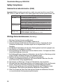
VCCI Class B Compliance (Japan)
CE Mark Declaration of Conformance (for EMI and Safety -
Europe)
This is to certify that this product complies with ISO/IEC Guide 22 and EN45014.
It conforms to the following specifications:
EMC: EN55022(1988)/CISPR-22(1985) class B
EN60555-2(1995) class B
EN60555-3
IEC1000-4-2(1995) 4kV CD, 8kV AD
IEC1000-4-3(1995) 3V/m
IEC1000-4-4(1995) 1kV - (power line), 0.5kV - (signal line)
IEC1000-4-6(1995) 3Vrms
This product complies with the requirements of the Low Voltage Directive 73/23/
EEC and the EMC Directive 89/336/EEC.

CheetahSwitch Workgroup-3008A/3016A
12
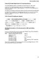
Safety Compliance
Underwriters Laboratories Inc. (USA)
Important! Before making connections, make sure you have the correct Cord
Set. Check it (read the label on the cable) against the following specification list.
egatloV snoitacificepSteSdroC
stloV021teSdroCdeifitreCASC/detsiLLU
drocrotcudnoceerhtTJSroTVSepyt;GWA81muminiM
teef51fohtgnelmumixaM
V521,A51detargulptnemhcattaepytgnidnuorg,edalblellaraP
stloV042teSdroCdeifitreCASC/detsiLLU
)aciremAhtroN(drocrotcudnoceerhtTJSroTVSepyt;GWA81muminiM
teef51fohtgnelmumixaM
V521,A51detargulptnemhcattaepytgnidnuorg,edalbmednaT
stloV042
)ylnoeporuE(
htiwsrotcudnoceerhtgnivahdrocF-VV50HhtiwteSdroC
²mm57.0foretemaidmuminim
V052,A01detargulpelam;elcatpecer023-CEI
Wichtige Sicherheitshinweise (Germany)
1. Bitte lesen Sie diese Hinweise sorgfältig durch.
2. Heben Sie diese Anleitung für den späteren Gebrauch auf.
3. Vor jedem Reinigen ist das Gerät vom Stromnetz zu trennen. Verwenden Sie keine
Flüssigoder Aerosolreiniger. Am besten eignet sich ein angefeuchtetes Tuch zur
Reinigung.
4. Die Netzanschlu ßsteckdose soll nahe dem Gerät angebracht und leicht zugänglich sein.
5. Das Gerät ist vor Feuchtigkeit zu schützen.
6. Bei der Aufstellung des Gerätes ist auf sicheren Stand zu achten. Ein Kippen oder Fallen
könnte Beschädigungen hervorrufen.
7. Die Belüftungsöffnungen dienen der Luftzirkulation, die das Gerät vor Überhitzung schützt.
Sorgen Sie dafür, daß diese Öffnungen nicht abgedeckt werden.
8. Beachten Sie beim Anschluß an das Stromnetz die Anschlußwerte.
9. Verlegen Sie die Netzanschlußleitung so, daß niemand darüber fallen kann. Es sollte
auch nichts auf der Leitung abgestellt werden.
10. Alle Hinweise und Warnungen, die sich am Gerät befinden, sind zu beachten.
11. Wird das Gerät über einen längeren Zeitraum nicht benutzt, sollten Sie es vom Stromnetz
trennen. Somit wird im Falle einer Überspannung eine Beschädigung vermieden.
12. Durch die Lüftungsöffnungen dürfen niemals Gegenstände oder Flüssigkeiten in das
Gerät gelangen. Dies könnte einen Brand bzw. elektrischen Schlag auslösen.
13. Öffnen sie niemals das Gerät. Das Gerät darf aus Gründen der elektrischen Sicherheit
nur von authorisiertem Servicepersonal geöffnet werden.

Quick Installation Guide
13
13
14. Wenn folgende Situationen auftreten ist das Gerät vom Stromnetz zu trennen und von
einer qualifizierten Servicestelle zu überprüfen:
a. Netzkabel oder Netzstecker sind beschädigt.
b. Flüssigkeit ist in das Gerät eingedrungen.
c. Das Gerät war Feuchtigkeit ausgesetzt.
d. Wenn das Gerät nicht der Bedienungsanleitung entsprechend funktioniert oder
Sie mit Hilfe dieser Anleitung keine Verbesserung erzielen.
e. Das Gerät ist gefallen und/oder das Gehäuse ist beschädigt.
f. Wenn das Gerät deutliche Anzeichen eines Defektes aufweist.
15. Zum Netzanschluß dieses Gerätes ist eine geprüfte Leitung zu verwenden. Für einen
Nennstrom bis 6A und einem Gerätegewicht größer 3kg ist eine Leitung nicht leichter als
H05VV-F, 3G, 0.75mm
2
einzusetzen.
Der arbeitsplatzbezogene Schalldruckpegel nach DIN 45 635 Teil 1000 beträgt
70dB(A) oder weniger.
Warranty
Accton warrants to the original owner that the product delivered in this package
will be free from defects in material and workmanship for a period of three (3)
years from the date of purchase from Accton or its Authorized reseller. For the
warranty to apply, you must register your purchase by returning the registration
card indicating the date of purchase and including proof of purchase. There will
be a minimal charge to replace consumable components, such as fuses, power
transformers, and mechanical cooling devices. The warranty does not cover the
product if it is damaged in the process of being installed. Accton recommends
that you have the company from whom you purchased this product install it.
THE ABOVE WARRANTY IS IN LIEU OF ANY OTHER WARRANTY, WHETHER
EXPRESS, IMPLIED OR STATUTORY, INCLUDING BUT NOT LIMITED TO ANY
WARRANTY OF MERCHANTABILITY, FITNESS FOR A PARTICULAR
PURPOSE, OR ANY WARRANTY ARISING OUT OF ANY PROPOSAL,
SPECIFICATION OR SAMPLE. ACCTON SHALL NOT BE LIABLE FOR
INCIDENTAL OR CONSEQUENTIAL DAMAGES. ACCTON NEITHER ASSUMES
NOR AUTHORIZES ANY PERSON TO ASSUME FOR IT ANY OTHER
LIABILITY.

ES3008A
ES3016A
E012000-R05
150917-101
-
 1
1
-
 2
2
-
 3
3
-
 4
4
-
 5
5
-
 6
6
-
 7
7
-
 8
8
-
 9
9
-
 10
10
-
 11
11
-
 12
12
-
 13
13
-
 14
14
-
 15
15
-
 16
16
-
 17
17
-
 18
18
-
 19
19
-
 20
20


Accton Technology 3008A Installationsanleitung
- Typ
- Installationsanleitung
in anderen Sprachen
Verwandte Artikel
-
Accton Technology ES3508-TX Quick Installation Manual
-
-
-
-
-
-
-
-
-