Boston Acoustics DSI 250 Bedienungsanleitung
- Kategorie
- Soundbar-Lautsprecher
- Typ
- Bedienungsanleitung

DSi
®
Designer In-Wall/In-Ceiling Speakers
DSi
®
Designer Montaje empotrado Sistemas de altavoces
Systèmes d’enceintes encastrées DSi
®
de la série Designe
DSi
®
-Designer-Serie Einbau-Lautsprechersysteme
DSi250
DSi260
DSi280
SPECIFICATIONS
DSi250 DSi260 DSi280
FREQUENCY RESPONSE (±3dB) 75Hz-20kHz 65Hz-20kHz 50Hz-20kHz
RECOMMENDED AMPLIFIER POWER 10-90 watts 10-90 watts 10-100 watts
NOMINAL IMPEDANCE 8 ohms 8 ohms 8 ohms
S
ENSITIVITY 1 watt (2.83v) at 1m 90dB 90dB 90dB
T
WEETER
3
⁄4" (20mm)
3
⁄4" (20mm)
3
⁄4" (20mm)
W
OOFER 5
1
⁄4"
(135mm) 6
1
⁄2" (165mm) 8
"
(203mm)
C
ROSSOVER FREQUENCY 6500Hz 4000Hz 5000Hz
EXTERNAL DIMENSIONS 10
1
⁄8 x 7
1
⁄2" (250 x191mm) 11
9
⁄16 x 8
13
⁄16" (294x224mm) 13
3
⁄8 x 10
5
⁄16" (340 x 262mm)
M
OUNTING HOLE CUTOUT 8
1
5
⁄1
6
x
6"
(227 x152mm) 1
0 x 7
3
⁄8" (254 x187mm) 1
1
1
3
⁄1
6
x
8
7
⁄8"
(
300 x 226mm)
M
OUNTING DEPTH (FROM SURFACE) 2
3
⁄8"
(
60mm) 3
"
(75mm) 3
3
⁄8"
(86mm)
OPTIONAL NEW CONSTRUCTION BRACKET NCB5 NCB6 NCB8
OPTIONAL COVER PLATE Cover5 Cover6 Cover8
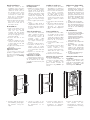
Required Clearances
Behind the mounting surface
there must be 1
1
⁄2-inches (38mm)
clearance on either side of the
short sides
.
Optional Brackets for
New Construction
For new construction installa-
tions, we offer new construc-
tion brackets. The NCB brack-
ets act as a perfect guide when
cutting the wallboard.
Model Bracket
DSi250 NCB5
DSi260
NCB6
DSi280 NCB8
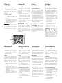
To Remove Grille
If you need to remove the
grille, gently lift it out at the
edges. Use a sharp pointed
instr
ument such as an awl or
the optional Boston Acoustics
®
grille pick.
Espacios libres necesarios
Detrás de la superficie de
montaje debe haber 38mm
libres a cada lado de los lat-
erales cortos.
Soportes opcionales para
construcción nueva
Para instalaciones en construc-
ciones nuevas ofrecemos
soportes opcionales. Los
soportes NCB sirven perfecta-
mente de guías para el corte de
cartón-yeso.
Modelo Soporte
DSi250 NCB5
DSi260 NCB6
DSi280
NCB8
Para quitar la r
ejilla
Si necesita quitar la r
ejilla, lev-
ántela con cuidado por los
extr
emos. Utilice una herramien-
ta afilada y puntiaguda, como un
punzón, o la ganzúa opcional de
Boston Acoustics para tal efecto.
Dégagements nécessaires
Derrière la surface de mon-
tage, un dégagem
Supports de fixation
facultatifs pour
constructions neuves
Pour les installations dans
des constructions neuves, nous
offrons des supports spéciaux.
Ces supports sont idéaux pour
servir de guides lors de la
découpe des murs.
Modèle Support
DSi250 NCB5
DSi260 NCB6
DSi280
NCB8
Retrait de la grille
Pour retirer la grille, soulevez-
la délicatement en la tenant
par les bords. Utilisez un instru-
ment pointu affilé, tel qu’un
poinçon ou l’instrument
Boston Acoustics prévu à cet
effet (en option).
Erforderliche
Mindestabstände
Hinter der Montagefläche
muss zu beiden Seiten der
kurzen Kanten 38 mm Spiel
vorhanden sein.
Optionale Halterungen für
Neubauten
Für die Montage in neuen
Gebäuden bieten wir beson-
dere Halterungen. Die NCB-
Halterungen sind eine ideale
Richtlinie, wenn
Gipskartonplatten geschnitten
werden.
Modell Halterung
DSi250 NCB5
DSi260 NCB6
DSi280
NCB8
Entfer
nen des Ziergitters
W
enn das Ziergitter entfernt
wer
den muss, heben Sie dieses
an den Kanten vorsichtig her
-
aus. V
erwenden Sie dazu ein
spitzes Werkzeug wie eine Ahle
oder den optionalen
Ziergitterspitz von Boston
Acoustics.
DSi460
DSi260
7
3
/
8
"
187mm
1
254mm
need measurements and DSi #
DSi250
DSi450
6
"
152mm
8
15
/
16
"
227mm
11
15
/
16
"
279mm
DSi460
DSi260
7
3
/
8
"
187mm
10
"
254mm
13
"
305mm
DSi480
DSi280
8
7
/
8
"
226mm
11
13
/
16
"
300mm
14
13
/
16
"
351mm
need measurements and DSi #
DSi250
DSi450
6
"
152mm
8
15
/
16
"
227mm
11
15
/
16
"
279mm
DSi460
DSi260
7
3
/
8
"
187mm
10
"
254mm
13
"
305mm
DSi480
DSi280
8
7
/
8
"
226mm
11
13
/
16
"
300mm
14
13
/
16
"
351mm
need measurements and DSi #
DSi250
DSi450
6
"
152mm
8
15
/
16
"
227mm
11
15
/
16
"
279mm

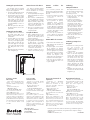
Prior to
Installation
IR Sensor Knockout
Each speaker has a knockout
molded into the speaker baffle
that will accommodate stan-
dard
1
⁄2-inch diameter infrared
(IR) sensors.
To use this feature:
1. Lay the speaker face down
on corrugated cardboard.
The packing material may
be used.
2. Use a #2 Phillips screwdriver
and hammer to punch out
the knockout from behind.
3. Install the IR sensor.
CAUTION: IR sensor range
and operating angle will be
r
educed by the speaker grille
and cloth. IR sensor will work
best on-axis to the face of the
speaker. Test before installing.
Antes del
montaje
Instalación de sensores IR
Cada altavoz cuenta con un
s
itio estampado en la carcasa
para alojar sensores estándar
infrarrojos de 1,2 cm de
diámetro.
Para utilizar esta característica:
1. Ponga el altavoz boca abajo
en un cartón rugoso. Puede
servir el material de embala-
j
e.
2. Utilice un destornillador de
estrella o cruz y un martillo
para perforar el agujero
ciego por detrás.
3. Instale el sensor IR.
PRECAUCIÓN: El alcance y
ángulo de funcionamiento del
sensor IR se verán reducidos
por la rejilla y la pantalla difu-
sora del altavoz. El sensor IR
funcionará mejor si se lo instala
derecho con respecto a la
parte frontal del altavoz.
Pruébelo antes de proceder a
la instalación.
Avant
l’installation
Pièce éjectable pour
capteur infrarouge
C
haque enceinte comporte
une pièce éjectable moulée
dans le haut-parleur à mem-
brane, dont le retrait permet de
loger un capteur infrarouge stan-
dard d’un diamètre de 1,28 cm.
Pour utiliser cette fonction :
1. Couchez l’enceinte face vers le
b
as sur du carton ondulé (vous
pouvez utiliser son carton
d’emballage).
2. Avec un tournevis cruciforme
et un marteau, éjectez la
pièce par l’arrière.
3. Installez le capteur
infrarouge.
ATTENTION : la grille et le dif-
fuseur de l’enceinte réduisent
la portée et l’angle de fonc-
tionnement du capteur IR. Pour
une performance optimale,
placez le capteur IR dans l’axe
de l’enceinte. Testez avant
d’installer.
Vor der
Installation
Aussparung für den IR-Sensor
Jeder Lautsprecher verfügt über
e
ine vorgeformte Aussparung in
der Lautsprecher-Schallwand, die
standardmäßige Infrarotsensoren
(IR-Sensoren) mit 12,7 mm
Durchmesser aufnehmen.
Zur Nutzung dieser Funktion:
1. Legen Sie den Lautsprecher
mit der Vorderseite nach
u
nten auf ein Stück
Wellpappe. Dazu kann das
Verpackungsmaterial ver-
wendet werden.
2. Schlagen Sie mit einem
Kreuz-schlitz-
Schraubendreher und
einem Hammer die
Aussparung von der
Rückseite her heraus.
3. Montieren Sie den IR-
Sensor.
VORSICHT: Reichweite und
Betriebsfeld des IR-Sensors
werden durch das Ziergitter
und den Scrim reduziert. Der
IR-Sensor funktioniert auf der
Achse zur Stirnseite des
Lautsprechers am besten. Die
Funktionsweise sollte vor der
Installation überprüft werden.
IR Sensor
Installation
Instructions
WARNING
Always turn off the amplifier
or receiver when connecting
speakers or any other compo-
nents to the system.
NOTE
This manual assumes the
installer possesses skill in the
pr
oper use of hand and power
tools, knowledge of local
building and fire codes, and a
familiarity with the environ-
ment behind the wall or ceiling
in which the speakers will be
installed.
Tools You’ll Need
1.
A utility knife, jig saw or
other tool for cutting the
required hole in the mount-
ing sur
face.
2. A #2 Phillips screwdriver.
3.
A wir
e cutter or stripper for
pr
eparing the speaker wir
es.
4. A pencil.
Instrucciones de
montaje
AVISO
Apague siempre el amplifi-
cador o el receptor cuando
conecte altavoces o cualquier
otro componente al sistema.
NOTA
En este manual se presupone
que el instalador posee habili-
dad en el manejo de her
ramien
-
tas tanto manuales como eléc
-
tricas, conocimiento sobre los
códigos de construcción local y
normas sobre incendios y que
está familiarizado con el
entorno tras el muro o techo en
los que se instalarán los altavo-
ces.
Her
ramientas necesarias
1.
Un navaja multiusos, una sier
-
ra caladora u otra herramien-
ta para cortar el agujero ade-
cuado en la super
ficie de
montaje.
2. Un destornillador de estrella
o cr
uz del número 2.
3. Un cortador de alambre o un
pelacables para pr
eparar el
cableado de los altavoces.
4. Un lápiz.
Instructions
d’installation
AVERTISSEMENT
Débranchez toujours l’amplifi-
cateur ou le récepteur avant de
connecter les enceintes ou tout
autre composant du système.
REMARQUE
Ce manuel suppose que l’in
-
stallateur sait utiliser les outils à
main et à moteur nécessaires à
l’installation, qu’il connaît la
réglementation en vigueur sur la
constr
uction et l’incendie, et
qu’il sait exactement ce qui se
trouve derrière les murs ou les
plafonds sur lesquels les
enceintes seront installées.
Outils nécessair
es
1. Un couteau, une scie à
découper ou tout autre outil
capable de découper l’orifice
nécessair
e dans la sur
face de
montage.
2. Un tournevis cruciforme No.
2.
3.
Une pince coupante ou à
dénuder pour prépar
er les fils
des enceintes.
4. Un crayon noir
Installationsan-
weisungen
ACHTUNG
Den Verstärker oder Empfänger
immer abstellen, wenn
Lautsprecher oder andere
Komponenten an das System
angeschlossen wer
den.
HINWEIS
Dieses Handbuch setzt voraus,
dass der Einbauer im Umgang mit
Hand- und Elektr
owerkzeugen
versiert ist, die örtlichen Bau- und
Brandschutzvorschriften kennt
und weiß, wo und welche
Leitungen in der Wand bzw. hinter
der Wandverkleidung verlaufen, in
der die Lautsprecher montiert
werden sollen.
Benötigte W
erkzeuge
1. Ein Messer, eine Stichsäge
oder anderes Werkzeug zum
Aus-schneiden des
notwendigen Lochs aus der
Montagefläche.
2.
Einen Kreuzschlitz-
Schraubendreher, Größe 2.
3.
Eine Drahtzange oder einen
Drahtstripper zur
Vorbereitung der
Lautsprecherkabel.
4.
Einen Bleistift.

R
etrofit Installations
1
. Mark the outline of the
installation hole using the
supplied template. Make a
small hole at the center of
t
he speaker location. Insert
a long, bent piece of wire
and rotate to confirm that
there are no obstructions
behind the chosen location.
2. Cut the installation hole.
3. Run the wire from the ampli-
f
ier location to the cutout.
Allow for an extra foot of
wire at the cutout.
All Installations
1. Strip
1
⁄2-inch (13mm) of insu-
lation from the wire, and
twist the wire strands
together. The DSi speaker
jack will accept either bare
wire up to 14-gauge, or sin-
gle banana plugs.
2. Connect the wire to the
speaker.
3. Slide the speaker into the
cutout as shown.The speak-
er must slide into the wall
woofer side first.
4. Tighten the Phillips mount-
ing screws.
Important: Do not over
tighten the screws.
If you wish to paint your
speakers or grilles it should be
done prior to installation of the
grille. Please see the
Painting
instructions.
I
nstalaciones para el
montaje trasero
1. Marque el contorno del agu-
jero con la plantilla sumin-
istrada. Haga un pequeño
a
gujero en el centro de la
ubicación del altavoz. Meta
un alambre doblado y déle
v
ueltas para asegurarse de
que no hay obstáculos
traseros en la posición elegi-
d
a.
2. Corte el agujero para la insta-
lación.
3
. Tienda el cable desde el
amplificador hasta el hueco
donde se ubicará al altavoz.
C
orte unos 30 cm más de lo
necesario.
Todas las instalaciones
1. Pele 13mm del aislante del
cable y retuerza el extremo
para agrupar los hilos. El
conector del altavoz dsi
aceptará tanto cable
desnudo de calibre 14 como
con clavijas sencillas tipo
banana.
2. Conecte el cable al altavoz.
3. Introduzca el altavoz en el
agujero como se indica.
Deben introducirse primero
en la pared del “lado del
woofer”.
4. Apriete los tornillos tipo
estrella de montaje.
Importante: no apriete
demasiado los tornillos.
Si quiere pintar los altavoces o
las rejillas deberá hacerlo antes
de la instalación de la rejilla.
Consulte las instrucciones para
pintarlos.
n
stallations améliorées
1. Tracez le contour de l’orifice
d’installation en utilisant le
gabarit fourni. Faites un petit
trou au centre de l’endroit où
sera placée l’enceinte.
Insérez-y un grand morceau
de câble replié, et faites
tourner celui-ci afin de vous
assurer qu’il n’existe aucun
obstacle derrière l’endroit
choisi.
2. Découpez l’orifice d’installa-
tion.
3. Amenez le câble de l’ampli à
l’orifice que vous venez de
découper, en prévoyant
30 cm de câble supplémen-
taire.
Toutes installations
1
. Dénudez 13 mm de câble,
et torsadez les fils souples
ensemble. La fiche de l’en-
ceinte dsi accepte les câbles
dénudés d’un diamètr
e max-
imum de 14, ou les fiches
bananes simples.
2.
Connectez le câble à l’en-
ceinte.
3. Intr
oduisez l’enceinte dans
l’orifice découpé comme
illustré ci-dessous. Les
enceintes doivent être intro-
duites dans le mur « côté
woofer » en premier.
4. Revissez les vis de fixation.
Important
: Ne resserrez pas
les vis excessivement.
Si vous voulez peindre les
enceintes ou les grilles, faites-
le avant l’installation des
grilles. Veuillez consulter les
instructions de
peinture qui
suivent.
E
inbau in eine fertige Fläche
1
. Den Umriss des
Installationslochs mit der mit-
gelieferten Maske anzeichnen.
In der Mitte der aus-zuschnei-
d
enden Fläche ein kleines Loch
erzeugen. Ein langes Stück
gebogenen Drahts in das Loch
einschieben, um zu prüfen, dass
hinter der gewählten Stelle
keine Hindernisse vorhanden
sind.
2
. Das Montageloch schneiden.
3. Das Kabel vom Verstärker zum
eben erzeugten Ausschnitt ver-
legen. An der Ausschnittstelle
e
twa 30 cm extra Kabellänge
vorsehen.
Alle Installationen
1. 13 mm Isolierung vom Kabel
entmanteln, und die Drahtlitzen
zusammendrehen. Der dsi-
Lautsprecheranschluss nimmt
entweder blanken Draht bis zu
AWG 14 oder einfache
Gabelschuhstecker auf.
2. Das Kabel an den Lautsprecher
anschließen.
3. Den Lautsprecher - wie abge-
bildet - in den Ausschnitt
schieben. Den Lautsprecher
müssen mit der „Woofer“-Seite
zuerst in die Wand geschoben
werden.
4. Die Kreuzschlitz-Befestigungs-
schrauben festziehen.
Wichtig: Die Schrauben nicht zu
fest anziehen.
Wenn die Lautsprecher oder
Ziergitter lackiert werden sollen,
muss dies vor der Installation des
Ziergitters geschehen (siehe
Anweisungen zum
Lackieren).
5. Insert the grille into the slots
in the baffle by gently apply-
ing pressure along the
edge.
5. Inserte la rejilla en las
ranuras del bafle presionan-
do ligeramente en los
extremos.
5. Insérez la grille dans les
fentes du haut-parleur à
membrane en appuyant
légèrement sur ses bords.
5. Fügen Sie das Ziergitter in
die Schlitze in der
Schallwand ein, indem Sie
entlang der Kante vorsichtig
andrücken.

P
ainting The Speaker Frame
The speakers may be painted
before or after they are installed.
They are already primed.
1. Insert the supplied paint mask
i
nto the frame of the speaker.
2. Paint the frame. If you are using
spray paint, apply two light
coats. If you are applying paint
with a brush or roller, thin the
paint and apply two very light
coats. This helps prevent exces-
sive paint buildup or “runs” on
t
he frame.
3. After the paint has dried, use
the finger pulls to remove the
paint mask.
Painting the Speaker Grille
1. Carefully remove the cloth from
t
he inside of the grille. Set it
aside in a clean location for later
reinstallation.
2. Paint the grille. If you are using
spray paint, apply two light
coats. If you are applying paint
with a brush or roller, thin the
paint and apply two very light
coats. This helps prevent paint
from filling the holes on the
grille.
3. After the paint is dry, reinstall the
cloth and grille logo.
P
intura el marco del altavoz
Los altavoces pueden pintarse
antes o después de la instalación.
Vienen de fábrica con can base
para pintura o primer.
1
. Inserte la plantilla (máscara) para
pintar suministrada en el marco
del altavoz.
2. Pinte el marco. Si utiliza pintura
en spray, aplique dos capas lig-
eras. Si utiliza pincel o rodillo,
diluya la pintura y aplique dos
capas muy delgadas. Esto evi-
t
ará el exceso de pintura y el
“corrimiento” de la misma.
3. Una vez seca la pintura, tire de
los lugares previstos en la más-
cara para retirarla.
La rejilla del altavoz
1
. Quite cuidadosamente la tela
del interior de la rejilla. Déjela
aparte en sitio limpio para su
posterior instalación.
2. Pinte la rejilla. Si utiliza pintura en
spray, aplique dos capas ligeras.
Si utiliza pincel o un rodillo,
diluya la pintura y aplique dos
capas muy delgadas. Esto evi-
tará el exceso de pintura y el
“corrimiento” de la misma.
3. Cuando la pintura esté seca,
vuelva a colocar la tela y el logo.
P
einture Coffrets des
e
nceintes
Les enceintes peuvent être
peintes avant ou après leur installa-
tion. Elles ont déjà reçu une couche
de fond.
1 Insérez le masque à peinture
fourni dans le coffret de
l
’enceinte.
2. Peignez le coffret. Si vous utilisez
de la peinture au pistolet,
appliquez deux couches
légères. Si vous appliquez la
peinture avec un pinceau ou un
rouleau, diluez-la et appliquez
deux couches très légères. Vous
é
viterez ainsi une accumulation
excessive de peinture ou des
coulées sur le coffret.
3. Une fois que la peinture est
sèche, utilisez les languettes
pour retirer le masque de pein-
ture.
Peinture Grille des enceintes
1. Ôtez le tissu de l’intérieur de la
grille. Mettez-le de côté dans un
endroit propre.
2. Peignez la grille. Si vous utilisez
de la peinture au pistolet,
appliquez deux couches légères.
Si vous appliquez la peinture
avec un pinceau ou un r
ouleau,
diluez-la et appliquez deux
couches très légères. Vous
éviterez ainsi que la peinture ne
remplisse les tr
ous de la grille.
3. Une fois que la peinture est
sèche, réinstallez le tissu et le
logo de la grille.
L
ackierung
L
autsprecherrahmen
D
ie Lautsprecher können vor oder
nach der Installation lackiert werden.
S
ie sind bereits mit einer
Grundierung versehen.
1. Legen Sie die mitgelieferte
Lackierungsmaske in den
Lautsprecherrahmen.
2
. Lackieren Sie den Rahmen.
Wenn Sie den Lack aufsprühen,
m
üssen zwei dünne Schichten
aufgetragen werden. Wenn
Lack mit einem Pinsel oder einer
Walze aus der Dose aufgetra-
gen wird, verdünnen Sie erst
den Lack und tragen dann zwei
ganz dünne Schichten auf. Dies
v
erhindert übermäßig dicke
Lackansammlungen oder Lack-
„
Tränen“ auf dem Rahmen.
3. Nach dem Trocknen des Lacks
ziehen Sie die
Lackierungsmaske an den
Fingerlaschen ab.
Lackierung Lautsprecher-
Ziergitter
1. Entfernen Sie vorsichtig das Tuch
von der Innenseite des
Ziergitters. Legen Sie es zur
späteren Installation an einem
sauberen Ort ab.
2. Lackieren Sie das Ziergitter.
Wenn Sie den Lack aufsprühen,
müssen zwei dünne Schichten
aufgetragen werden. Wenn Lack
mit einem Pinsel oder einer
Walze aus der Dose aufgetragen
wird, verdünnen Sie
erst den
Lack und tragen dann zwei ganz
dünne Schichten auf. Damit
wird verhinder
t, dass sich die
Löcher des Ziergitters mit Lack
füllen.
3. Nachdem der Lack trocken ist,
installieren Sie das Tuch und das
Ziergitter-Logo.
If Service Seems
Necessary
First, contact the dealer from
whom you purchased the
speakers. If that is not possible,
write to:
Boston Acoustics, Inc.
300 Jubilee Drive
Peabody, MA 01960 USA
Or contact us via e-mail at:
We will promptly advise you of
what action to take. If it is nec-
essary to return your speaker to
the factory, please ship it pre-
paid. After it has been repaired,
we will return it freight prepaid
in the United States and
Canada.
Si se necesita
servicio técnico
Diríjase a la tienda donde
adquirió el sistema. Si esto no
es posible, escriba a:
Boston Acoustics, Inc.
300 Jubilee Drive
Peabody, MA 01960 USA
O póngase en contacto con
nosotros a través de nuestra pági-
na web,
En un breve plazo le comuni-
caremos el procedimiento que
debe seguir. Si fuera necesario
devolver los altavoces a fábrica,
le rogamos lo haga con portes
pagados. Una vez reparado el
sistema, lo devolveremos con
portes pagados en los Estados
Unidos y Canadá.
Pour toute demande de
réparation
Contactez le détaillant
auprès duquel vous avez
acheté les enceintes. Si cela
n’est pas possible, écrivez à
l’adresse suivante :
Boston Acoustics, Inc.
300 Jubilee Drive
Peabody, MA 01960 USA
ou contactez-nous sur notre site
Web à :
Nous vous indiquerons sans
délai la marche à suivre. Si vous
devez renvoyer un article à l’u-
sine, veuillez l’expédier en port
payé. Une fois la réparation
effectuée, nous vous le renver-
rons en port payé (aux États-
Unis et au Canada).
Reparaturanforderung
W
enden Sie sich bitte erst an
den Fachhändler, von dem Sie die
Lautsprecher gekauft haben.
W
enn dies nicht möglich ist,
schreiben Sie an:
Boston Acoustics, Inc.
300 Jubilee Drive
Peabody, MA 01960 USA
Oder nehmen Sie über folgende
W
ebsite mit uns Kontakt auf:
suppor
Wir werden Ihnen unverzüglich
mitteilen, wie Sie vorgehen sollen.
W
enn der Lautsprecher an das
Werk zurückgeschickt werden
muss, senden Sie ihn bitte fracht
-
frei zurück. Nach der Reparatur
wird er in den USA und in Kanada
frachtfrei an Sie zurückgesandt.
Boston, Boston Acoustics, the Boston Acoustics logo, and DSi are registered
trademarks of Boston Acoustics, Inc. Specifications are subject to change
without notice.
© 2006 Boston Acoustics, Inc.
142-001490-4
300 Jubilee Drive
Peabody, MA 01960 USA
978.538.5000
bostonacoustics.com

Boston Acoustics, Inc.
Rich Gorzynski, Project Manager: 978/538-5141
Product Manual: DSI250 & DSI260 DSi280
Date: 6/15/04 Scale: 100%
BA P/N: 142-001490-4
Note: Dimensions in millimeter
Keylines not to print
Revisions: Rev 2; Addition of DSi260
Rev 3; Reduction of doc size.
Rev 4; Addition of DSi280 and
RoHs Notes
This drawing and data embody proprietary designs and information which is the confidential property of Boston Acoustics,
None of which shall be copied, reproduced, disclosed to others, proposed or used in whole or in part, for any purpose
without express written permission of a duly authorized agent of Boston Acoustics. This drawing is subject to recall by
Boston Acoustics at any time. It is being submitted in confidence and patent rights are reserved by Boston Acoustics.
All Material must be compliant with the
latest revision of the Boston Acoustics
Environmental Purchasing Specification
No.142-002522
-
 1
1
-
 2
2
-
 3
3
-
 4
4
-
 5
5


Boston Acoustics DSI 250 Bedienungsanleitung
- Kategorie
- Soundbar-Lautsprecher
- Typ
- Bedienungsanleitung
in anderen Sprachen
Verwandte Papiere
-
Boston Acoustics HSi Series HSi 485 Benutzerhandbuch
-
Boston Acoustics HSI 255 Benutzerhandbuch
-
Boston Acoustics Speaker CS 275 Benutzerhandbuch
-
Boston Acoustics DSI455 Benutzerhandbuch
-
-
-
Boston Acoustics HSI 460T2 Benutzerhandbuch
-