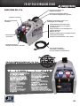
JB F6-DP-308 F6-DP-250 AU/EU Refrigerant Recovery Unit Benutzerhandbuch
- Typ
- Benutzerhandbuch

TM WWW.JBIND.COM 800.323.0811 [email protected]
JB INDUSTRIES
CONNECT WITH US
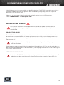
OPERATING INSTRUCTIONS
FOR MODELS: F6-DP-250 AND F6-DP-250-AU
TO LEARN MORE
ABOUT THE F6-DP-250
SCAN HERE:

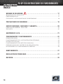
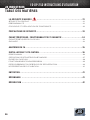
TABLE OF CONTENTS
SAFETY FIRST ������������������������������������������������������������������������������� 3
PRODUCT SAFETY ������������������������������������������������������������������������������������������������������������������� 3
RESPONSIBILITY ���������������������������������������������������������������������������������������������������������������������� 3
COPYRIGHT AND DECLARATION OF CONFORMITY ������������������������������������������������������������ 4
SAFETY PRECAUTIONS ��������������������������������������������������������������������� 5
SPECIFICATIONS, FEATURES AND WARRANTY ��������������������������������������� 6
F6-DP-250 SPECIFICATIONS ��������������������������������������������������������������������������������������������������� 6
WARRANTY ������������������������������������������������������������������������������������������������������������������������������� 6
ANATOMY OF THE F6 ����������������������������������������������������������������������� 7
SETUP AND OPERATION ������������������������������������������������������������������� 8
GETTING STARTED������������������������������������������������������������������������������������������������������������������� 8
STANDARD RECOVERY OPERATION �������������������������������������������������������������������������������������� 9
PURGING F6-DP-250 �������������������������������������������������������������������������������������������������������������� 10
PUSH-PULL OPERATION ������������������������������������������������������������������������������������������������������� 11
COOLING THE RECOVERY TANK ������������������������������������������������������������������������������������������ 11
SPECIAL OPERATING NOTES ������������������������������������������������������������������������������������������������ 12
MAINTENANCE ������������������������������������������������������������������������������13
TROUBLESHOOTING �����������������������������������������������������������������������13
SERVICE ��������������������������������������������������������������������������������������14
TM2
JB INDUSTRIES

Thank you for buying the JB Industries F6-DP-250 Refrigerant Recovery Machine�
For optimal F6-DP-250 performance, read this manual carefully before use�
For additional questions or assistance, contact JB Industries�
USA: +1.800.323.0811 or sales@jbind.com
SAFETY FIRST
This symbol is intended to alert the presence of critical items regarding operating,
safety and maintenance (servicing) instructions in this manual�
PRODUCT SAFETY
F6-DP-250 is a recovery machine for a broad range of refrigerants� Recovering refrigerants
into separate storage tanks involves a process of gas compression� This results in high
pressures within the machine, the connecting hoses, and the storage tank�
High pressure systems can cause accident or injury if not handled properly,
and with care�
Refrigerant hoses must have shut-off devices within 30�5 cm (12 in�) of the ends, to reduce the
likelihood of refrigerant leakage to the atmosphere when changing tanks or setups�
RESPONSIBILITY
Do not use F6-DP-250 unless properly trained in the recovery process� Operation of
this machine by unqualified personnel is potentially dangerous�
3
JB INDUSTRIES

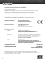
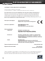
COPYRIGHT AND DECLARATION OF CONFORMITY
© 2016 All rights reserved�
Reproduction or adaptation of any part of this manual without permission is unlawful�
This declaration is issued under the sole responsibility of the manufacturer
JB Industries, Inc� The object of the declaration is to certify that this equipment,
designed and manufactured by JB Industries, Inc�, is in conformity with the relevant
Community harmonization legislation� It has been constructed in accordance with good
engineering practice in safety matters in force in the Community and does
not endanger the safety of persons, domestic animals or property when properly
installed and maintained and used in applications for which it was made�
Equipment Description: F6-DP-250/F6-DP-250-AU
Refrigerant Recovery Machine
Applicable Directives: 2014/30/EU General EMC
2011/65/EU RoHS
2014/35/EU Low Voltage Directive
Applicable Standards:
Safety: EN 60335-1:2012/A11:2014
Household and similar electrical appliances –
Safety – Part 1: General requirements
Emissions: EN 55014-1:2006/A2:2011 / CISPR 14-1:2005/A2:2011
Electromagnetic compatibility – Requirements – for
household appliances, electric tools and similar
apparatus – Part 1: Emissions
RoHS: EN 50581:2013
Technical documentation for the assessment of
electrical and electronic products with respect to the
restriction of hazardous substances
CE Implementation Date April 20, 2016
Authorized Representative Dave Madden
Director of Manufacturing
Any questions relative to this declaration or to the safety of JB Industries products
should be directed, in writing, to the quality assurance department at JB Industries, Inc�,
601 North Farnsworth, Aurora, IL 60505�
TM4
JB INDUSTRIES

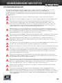
SAFETY PRECAUTIONS
Read this manual before using F6-DP-250 to become familiar with its specifications and
operation� Review the Safety Data Sheets (SDS) and the Temperature/Vapor Pressure
information for the proper safety and handling requirements regarding the refrigerants
being recovered�
Wear gloves, eye protection and foot protection when working on refrigeration systems�
Refrigerant vapor can be hazardous and its by-products can be lethal�
Motors and switches can generate sparks and can be especially dangerous in
flammable environments� Work only in well-ventilated areas, with mechanical ventilation
that provides at least four air change rates per hour� Do not work in an enclosed
area without appropriate safety equipment� It may be necessary to install a separate
circulation fan�
Never use oxygen for leak detection� Oxygen can become an explosive mixture in the
presence of oil and pressure� Perform leak detection in accordance with recommended
practice only� For best results, use a refrigerant leak detector, such as JB Industries
Aurora or Prowler�
Never mix refrigerants� Use separate storage cylinders, hoses, and filters for each type
of refrigerant recovered� Store refrigerants in a cool, dry place�
Never overfill a storage container� Overfilled tanks can rupture and explode� Use a
refrigerant scale such as JB Industries ATLAS to prevent overfill�
When opening service or cylinder valves, open slowly, to ensure all connections are
secure and free of danger�
Disconnect power before moving or servicing F6-DP-250�
The risk of electric shock and exposure to hot compressor parts is possible if the
F6-DP-250 covers are removed� F6-DP-250 should only be opened by a qualified
technician who has been trained in basic electronics and refrigeration�
Use only the power cord supplied by JB Industries� If the cord is lost or damaged,
contact JB Industries for information on obtaining a replacement�
When connected to the F6-DP-250, extension cord wiring can overheat under
conditions of high current draw� If an extension cord is necessary, use the shortest
possible length and only size 14 AWG or larger for 115 V (ac) or 1�00 mm2 or larger
for 230 V (ac)�
Do not use F6-DP-250 near open containers of gasoline or other flammable liquids�
This product is designed for use with refrigerants only� Only approved for use with
A1 (nonflammable) and A2L (mildly flammable) refrigerants� Any other uses of this
product are not recommended by JB Industries and could result in personal injury�
Use of this product other than intended is done at the user‘s own risk�
5
JB INDUSTRIES

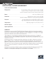
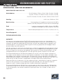
SPECIFICATIONS, FEATURES AND WARRANTY
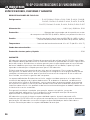
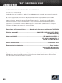
F6-DP-250 SPECIFICATIONS
Refrigerants��������������������������������������������� R-12, R-1234yf, R-134a, R-22, R-32, R-401A, R-401B,
R-401C, R-402A, R-402B, R-404A, R-407A, R-407B,
R-407C, R-408A, R-409A, R-410A, R-500, R-502, R-507
Power ����������������������������������������������������������������������������������������������������230 V (ac), 50/60 Hz, 5�5A
Protection ������������������������������������������������������������������������� High pressure switch cutoff at 550 PSI
(3�8 MPa, 38 bar) Compressor motor thermally protected
Pressure ����������������������������������������������������� Low side design pressure 350 PSI (2�4 MPa, 24 bar)
High side design pressure 550 PSI (3�8 MPa, 38 bar)
Temperature ���������������������������������������������������������������� Operating range 10 to 40°C (50 to 104°F)
Pollution degree ���������������������������������������������������������������������������������������������������������������������������2
Ingress protection �������������������������������������������������������������������������������������������������������������������IP20
WARRANTY
JB Industries warrants the F6-DP-250 Refrigerant Recovery Machine to be free from defects
of materials or workmanship for three years from the date of purchase� JB Industries does not
warrant any machine that has been subjected to misuse, negligence, or accident, or has been
repaired or altered by anyone other than JB Industries�
The compressor is warranted for a period of three years by the manufacturer� To keep this
warranty in force, a filter (included) must be used on the inlet port or hose at all times to
prevent particulates from entering the compressor� Failure to use the included filter will void the
compressor warranty�
JB Industries liability is limited to repairing or replacing, at its option, a defective machine or
part� If a defect arises, a valid claim must be received by JB Industries, with transportation
prepaid, no later than thirty (30) days after the warranty period expires� JB Industries will
determine whether the machine has malfunctioned due to defective materials or workmanship�
This warranty is in lieu of all other warranties, expressed or implied, whether of merchantability,
fitness for a particular purpose, or otherwise� All such other warranties are expressly
disclaimed�
JB Industries shall have no liability in excess of the price paid to JB Industries for F6-DP-250,
plus return transportation charges prepaid� JB Industries shall have no liability for any
incidental or consequential damages� All such liabilities are excluded�
TM6
JB INDUSTRIES

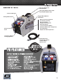
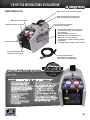
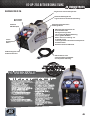
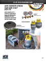
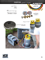
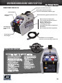
F6 FEATURES
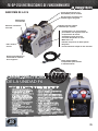
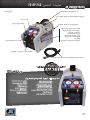
ANATOMY OF THE F6
Heavy-Duty Metal Handle with
Comfortable Rubber Grip
-Micro-Channel Condenser
for Industry Leading
Recovery Rates
-Large Fan for Superior
Heat Dissipation
-1 Full Horsepower Motor
-Powerful Dual Piston Compressor
-Circuit Breaker
-Simple Two-Valve Operation
Carrying Strap with
Shoulder Pad
Rugged Blow Molded
Outer Shell
Recessed Gauges
Sturdy Metal Knobs
Easy-to-Access
Filter
Detachable and
Replaceable Power
Cord for Easy
Maintenance
Self-Purge Without
Changing Hoses
7
JB INDUSTRIES

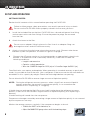
SETUP AND OPERATION
GETTING STARTED
Review the full contents of this manual before operating the F6-DP-250�
Failure to follow proper safety precautions can result in personal injury or death�
Do not use the F6-DP-250 unless properly trained in the recovery process�
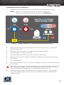
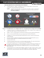
1 Install the included filter on the inlet� F6-DP-250 has a female refrigerant flare fitting,
and connects with male flare fittings� Ensure the protective plugs are removed
from the filter�
2 Attach the hoses to the filter�
Do not use an adapter fitting in place of a filter� Use of an adapter fitting can
damage the valves and will void the warranty�
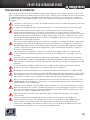
3 Attach a hose from the discharge valve to the recovery tank� Connect other hoses
between system components as shown in Figure 1 on page 9�
4 Connect the AC power cord to a circuit protected by an appropriately sized circuit
breaker� If an extension cord is absolutely necessary, make sure it meets the
following conditions:
• Length is not excessive
• Contains a safety ground wire
• Wire size 14 AWG or larger for 115 V (ac) or 1.0 mm2 or larger for 230 V (ac)
Overfilled tanks can rupture and explode� When operating in standard recovery or push-pull
mode, it is possible to overfill the tank� Use a refrigerant scale to ensure that the tank does not
exceed 80% of its capacity by weight� Check the tank weight before transporting�
Do not allow the F6-DP-250 to recover large amounts of liquid too quickly�
NOTE: During the refrigerant recovery process, when a significant amount of liquid is
present and enters the recovery machine too quickly, it can sometimes be
referred to as a “liquid slug” or “slugging�”
A liquid slug can activate the High Pressure shutoff and prolong the refrigerant recovery
process� If the F6-DP-250 recovers large amounts of liquid too quickly (or a liquid slug is
present),
a loud knocking will sound from the compressor�
Compressor damage caused by recovering a large amount of liquid too quickly is not covered
by the compressor warranty�
Monitor the recovery process carefully� If the compressor begins to knock:
• Throttle the INLET valve clockwise, or
• Adjust the MANIFOLD gauge valves until the knocking stops.
TM8
JB INDUSTRIES

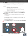
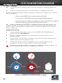
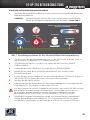
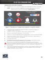
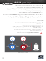
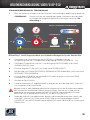
STANDARD RECOVERY OPERATION
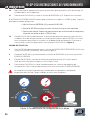
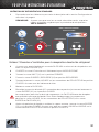
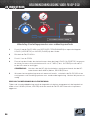
1 Connect all cables and hoses as described in Setup and Operation on page 8�
NOTE: Make sure all connections are tight, and that the cables and
hoses do not interfere with the recovery process (See Figure 1).
2 Make sure the hose connecting the F6-DP-250 to the recovery tank is attached to
the LIQUID port (LP)�
3 OPEN the LP valve on the tank — Keep the VAPOR port CLOSED�
4 Rotate the INLET valve (V1) to CLOSE�
5 Set the PURGE/RECOVER valve (V2) to the RECOVER position�
6 Slowly rotate the LIQUID valve on the MANIFOLD gauge to OPEN� Make sure there
are no leaks�
7 Turn on F6-DP-250�
8 Monitor the inlet pressure (LP, Low Pressure Gauge) and slowly rotate the INLET valve
(V1) to OPEN�
The compressor may emit a knocking sound if the F6-DP-250 attempts to recover a
significant amount of liquid� To prevent damage to the compressor, throttle the LIQUID
valve on the MANIFOLD gauge set, or the F6-DP-250 INLET valve (V1)�
9 Once the liquid has been recovered, transfer the remaining vapor; rotate the INLET
valve (V1) to OPEN� Make sure the LIQUID and VAPOR valves on the MANIFOLD
gauge are OPEN�
Figure 1 - Setup Procedure for Standard Refrigerant Recovery
9
JB INDUSTRIES

10 Continue to operate until the LP gauge indicates the required vacuum has been
obtained�
11 Turn off the F6-DP-250 and close the INLET valve (V1) — Wait five minutes�
If the MANIFOLD gauge indicates pressure has risen above 0 PSIG (0 bar), refrigerant is
still present�
• Open the INLET valve (V1) and turn on F6-DP-250.
• Run the F6-DP-250 until the required vacuum is reached again.
• Wait five minutes. Repeat this process until all refrigerant is removed and
pressure is 0 PSIG (0 bar), or less.
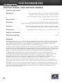
12 Immediately purge the F6-DP-250� Purging is necessary to remove any residual
refrigerant from inside the F6-DP-250 internal components as well as the hose from
the outlet to the recovery tank� Refer to Purging the F6-DP-250 and Figure 2 below�
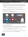
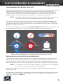
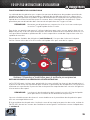
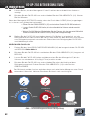
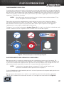
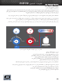
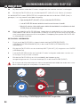
PURGING F6-DP-250
1 While the F6-DP-250 is off, rotate the PURGE/RECOVER valve (V2) to PURGE�
See (See Figure 2).
2 Turn on the F6-DP-250 and slowly rotate the INLET valve (V1) to PURGE�
3 Run the F6-DP-250 and monitor the LP gauge until a vacuum of 20 In/Hg (0�7 bar)
or more is achieved�
4 Turn off the F6-DP-250 and immediately close the valves on the recovery tank�
Rotate the inlet valve (V1) to CLOSE�
The hose and the discharge port will contain a small amount of pressurized refrigerant�
Exercise care when removing this hose�
Figure 2 - Setup Procedure for Purging
TM10
JB INDUSTRIES

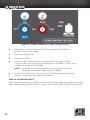
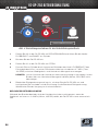
COOLING THE RECOVERY TANK
The F6-DP-250 can be used to pre-cool (or sub-cool) the recovery tank, if the head pressure
is too high to complete the recovery process� If the ambient pressure is too high, high head
pressure can occur when working with certain refrigerants that have a high vapor pressure�
NOTE: The recovery tank must contain five pounds or more of liquid,
to allow the pressure differential to develop�
Sub-cooling the tank before starting the recovery process may provide little or no benefit�
If the recovery process stalls because of high head pressure, turn off the F6-DP-250, close the
hose valves, and reconfigure the setup as shown in (See Figure 4).
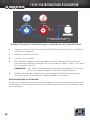
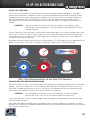
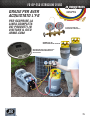
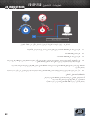
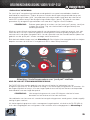
PUSH-PULL OPERATION
The push-pull recovery method is used to move large amounts of liquid refrigerant� During
this process, the recovery unit pulls vapor from the recovery cylinder and produces a high
pressure discharge gas that pushes liquid out of the HVAC system and back into the recovery
cylinder� Recovery rates above 15 pounds per minute can be achieved when using this
procedure�
NOTE: Do not attempt the push-pull process unless the system contains
at least 15 pounds (7 Kg) of liquid that can be easily isolated�
To prevent overfill, use the scale to make sure the tank does not surpass 80% capacity
by weight� Monitor the tank weight carefully as 80% capacity maybe reached quickly during
push-pull due to its rapid transfer�
Connect the refrigerant hoses (See Figure 3). A sight glass, not included, can help determine
when the liquid has been transferred and vapor remains�
Figure 3 - Setup Procedure For Push-Pull Method
11
JB INDUSTRIES

1 Rotate V2 on the F6-DP-250 to RECOVER and open the LIQUID and
VAPOR valves on the cylinder�
2 Turn on the F6-DP-250�
3 Rotate V1 to OPEN�
4 On the cylinder, throttle the flow of liquid by slowly closing the LIQUID
valve to achieve a minimum pressure differential of 100 PSIG (0�7 MPa, 7 bar)
between the LP and the HP gauges�
NOTE: To prevent the HP cutoff switch from actuating, do not allow the
HP gauge to exceed 550 PSIG (3�8 MPa, 38 bar)�
5 Once the recovery tank is cold, turn off the F6-DP-250 and reconfigure the
setup for standard recovery� Repeat as needed�
SPECIAL OPERATING NOTES
During standard operation, the High Pressure switch will reset when the head pressure drops
below approximately 425 PSI (2�9 MPa, 29 bar), and the F6-DP-250 will restart automatically�
Figure 4 - Setup Procedure for Sub-Cooling Method
TM12
JB INDUSTRIES

MAINTENANCE
With minimal but important maintenance, the F6-DP-250 can provide many seasons of reliable
service� After each use, clean the F6-DP-250 with a damp cloth to remove dirt and oils�
Do not use gasoline or other hazardous solvents to clean F6-DP-250; this can damage
the plastic enclosure� Standard household detergent or isopropyl alcohol may be used,
but do not allow liquid to penetrate the outer case�
Make sure the inlet and discharge ports are protected during transit and storage; keep the
inner diameter and the outer threads clear and clean�
NOTE: For best results, leave the filter connected to the inlet port,
and change the filter regularly�
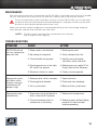
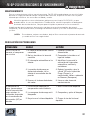
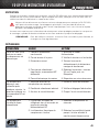
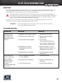
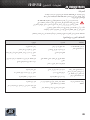
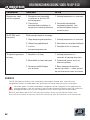
TROUBLESHOOTING
PROBLEM CAUSE ACTION
F6-DP-250 will not
turn on; compressor
does not start
1. Power cord is not attached
2. No voltage at receptacle
3. Circuit breaker has opened
4. Discharge pressure is too high;
HP switch has opened
5. Electronics failure in motor
1. Attach power cord
2. Verify voltage at job site
3. Identify cause of breaker
activation, rectify and reset
4. Reduce pressure; rotate V2 to
Purge, then back to Recovery
5. Factory service required
Compressor starts,
but falters within
minutes; pressure
indication on HP
gauge is high
1. Recovery tank valve is not open
2. Discharge hose blocked
3. Air in system/tank
1. Open tank valve
2. Check and clear blockage
3. Bleed air from system/tank
Compressor stops
intermittently
1. Vapor pressure of refrigerant in
tank is close to HP trip point
2. Thermal overload switch in
compressor is activating
1. Reduce tank temperature
2. Reduce amount of liquid being
pumped; let machine cool
before proceeding
13
JB INDUSTRIES

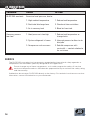
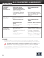
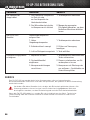
SERVICE
The F6-DP-250 uses electrical components recognized by international safety agencies or
components that have been specially designed for this application�
Do not change any of these components, as it could compromise safety� All service
work must be performed at a JB Industries-approved facility to maintain the safety rating
and the warranty�
If defective, do not return F6-DP-250 directly to the factory� For technical assistance or service
information, contact JB Industries or your wholesaler�
PROBLEM CAUSE ACTION
F6-DP-250 overheats Excessive head pressure, due to:
1. High ambient temperature
2. Restricted discharge hose
3. Air in recovery tank
1. Reduce tank temperature
2. Check and clear restriction
3. Bleed air from tank
Recovery process
too slow
1. Head pressure is too high
2. System refrigerant is frozen
3. Compressor seals are worn
1. Reduce tank temperature or
change tanks
2. Interrupt process to allow ice to
dissipate
3. Rebuild compressor with
service kit — contact wholesaler
for assistance
TM14
JB INDUSTRIES

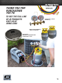
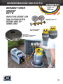
THANK YOU FOR
PURCHASING
THE F6
TO SEE THE FULL LINE
OF JB PRODUCTS
VISIT US AT
JBIND.COM
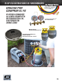
DS-20000S
WIRELESS REFRIGERANT
CHARGING SCALE
PATRIOTTM 2-VALVE
MANIFOLD
KOBRA® CLE
SERIES HOSE
EMPTY REFRIGERANT
TANK CYLINDERS
15
JB INDUSTRIES

ÍNDICE
NORMAS DE SEGURIDAD� ����������������������������������������������������������������17
SEGURIDAD DEL PRODUCTO ����������������������������������������������������������������������������������������������� 17
RESPONSABILIDAD ���������������������������������������������������������������������������������������������������������������� 17
COPYRIGHT Y DECLARACIÓN DE CONFORMIDAD ������������������������������������������������������������ 18
PRECAUCIONES DE SEGURIDAD ���������������������������������������������������������19
ESPECIFICACIONES, FUNCIONES Y GARANTÍA ���������������������������������������20
ESPECIFICACIONES DE F6-DP-250 ������������������������������������������������������������������������������������� 20
GARANTÍA ������������������������������������������������������������������������������������������������������������������������������� 20
ANATOMÍA DE LA F6 �����������������������������������������������������������������������21
CONFIGURACIÓN Y FUNCIONAMIENTO ������������������������������������������������22
PRIMEROS PASOS ������������������������������������������������������������������������������������������������������������������ 22
FUNCIONAMIENTO DE LA RECUPERACIÓN ESTÁNDAR ���������������������������������������������������� 23
PURGA DE F6-DP-250 ������������������������������������������������������������������������������������������������������������ 24
FUNCIONAMIENTO DEL MÉTODO PUSH-PULL ������������������������������������������������������������������� 25
REFRIGERACIÓN DEL DEPÓSITO DE RECUPERACIÓN� ���������������������������������������������������� 25
NOTAS SOBRE EL FUNCIONAMIENTO ESPECIAL ��������������������������������������������������������������� 26
MANTENIMIENTO ���������������������������������������������������������������������������27
RESOLUCIÓN DE PROBLEMAS �����������������������������������������������������������27
REVISIÓN ������������������������������������������������������������������������������������28
TM16
JB INDUSTRIESJB INDUSTRIES F6-DP-250 INSTRUCCIONES DE FUNCIONAMIENTO

Le agradecemos que haya comprado el Equipo de recuperación de refrigerante F6-DP-250
de JB Industries� Para conseguir un rendimiento óptimo de F6-DP-250, lea este manual
detenidamente antes de usar el equipo�
Si tiene preguntas adicionales o necesita ayuda, póngase en contacto con JB Industries�
Estados Unidos: +1.800.323.0811 / sales@jbind.com
NORMAS DE SEGURIDAD
El objetivo de este símbolo consiste en advertir al usuario de la existencia de aspectos
importantes relacionados con las instrucciones de mantenimiento (revisión), seguridad
y funcionamiento de este manual�
SEGURIDAD DEL PRODUCTO
F6-DP-250 es un equipo de recuperación para una amplia gama de refrigerantes� La
recuperación de refrigerantes en depósitos de almacenamiento independientes implica un
proceso de compresión de gas que provoca altas presiones en el equipo, las mangueras de
conexión y el depósito de almacenamiento�
Los sistemas de alta presión pueden provocar accidentes o lesiones si no se
manipulan correctamente y con cuidado�
Las mangueras refrigerantes deben incluir dispositivos de parada a unos 30,5 cm
(12 pulgadas) de los extremos para reducir la probabilidad de fuga de refrigerante a la
atmósfera al cambiar los depósitos o las configuraciones�
RESPONSABILIDAD
No utilice F6-DP-250 a menos que haya recibido la formación adecuada en el proceso
de recuperación� El uso de este equipo por parte de personal que no esté cualificado
puede ser peligroso�
17
JB INDUSTRIESJB INDUSTRIES
F6-DP-250 INSTRUCCIONES DE FUNCIONAMIENTO

COPYRIGHT Y DECLARACIÓN DE CONFORMIDAD
© 2016 Todos los derechos reservados�
Es ilegal reproducir o adaptar cualquier parte de este manual sin permiso�
Por la presente se certifica que este equipo, diseñado y fabricado por JB Industries Inc�,
601 N Farnsworth Ave; Aurora, IL 60505, EE� UU�, cumple los requisitos de seguridad
esenciales y se comercializa en el mercado de acuerdo con ellos� Se ha fabricado de
acuerdo con buenas prácticas de ingeniería en cuestiones de seguridad vigentes en
la Comunidad y no representa un peligro para la seguridad de las personas, animales
domésticos o propiedades siempre que se instale y se mantenga adecuadamente y se use
para las aplicaciones para las que está destinado�
Descripción del equipo: F6-DP-250/F6-DP-250-AU
Máquina de recuperación de refrigerante
Directrices aplicables: 2014/30/EU General EMC
2011/65/EU RoHS
2014/35/EU Directiva de bajo voltaje
Normas aplicables:
Seguridad: EN 60335-1:2012/A11:2014
Aparatos electrodomésticos y análogos -
Seguridad - Parte 1: Requisitos generales
Emisiones: EN 55014-1:2006/A2:2011 / CISPR 14-1:2005/A2:2011
Compatibilidad electromagnética - Requisitos - para
Electrodomésticos, herramientas eléctricas y similares
- Parte 1: Emisiones
RoHS: EN 50581:2013
Documentación técnica para la evaluación de
productos eléctricos y electrónicos en relación con la
restricción de sustancias peligrosas
Fecha de implantación de la CE 20 de Abril de 2016
Representante autorizado Dave Madden
Director de Fabricación
Todas las preguntas relacionadas con esta declaración o con la seguridad de los productos
de JB Industries se deben dirigir por escrito al departamento de garantía de calidad en la
dirección indicada anteriormente� 601 North Farnsworth, Aurora, IL 60505 (EE� UU)�
TM18
JB INDUSTRIES F6-DP-250 INSTRUCCIONES DE FUNCIONAMIENTO
JB INDUSTRIES

PRECAUCIONES DE SEGURIDAD
Lea este manual antes de utilizar F6-DP-250 para familiarizarse con sus especificaciones y
su funcionamiento� Revise las hojas de datos de seguridad (SDS)anipulación y seguridad
adecuados con relación a los refrigerantes que se van a recuperar�
Use guantes, gafas protectoras y calzado de seguridad cuando trabaje con sistemas
de refrigeración�
El vapor refrigerante puede ser peligroso y su inhalación a través de los productos
puede ser letal�
Los motores y conmutadores pueden generar chispas y ser especialmente peligrosos
en entornos inflamables� Trabaje solo en zonas que estén bien ventiladas, con
ventilación mecánica que proporcione al menos cuatro renovaciones de aire por
hora� No trabaje en un área cerrada sin el equipo de seguridad adecuado� Puede ser
necesario instalar un ventilador de circulación independiente�
No utilice nunca oxígeno para la detección de fugas� El oxígeno se puede convertir en
una mezcla explosiva en presencia de combustible y presión� Realice una detección de
fugas de conformidad únicamente con la práctica recomendada� Para obtener mejores
resultados, utilice un detector de refrigerante como, por ejemplo, JB Industries Aurora o
Prowler�
No mezcle nunca los refrigerantes� Utilice filtros, mangueras y cilindros de
almacenamiento independientes para cada tipo de refrigerante recuperado� Almacene
los refrigerantes en un lugar frío y seco�
No llene nunca el contenedor de almacenamiento en exceso� Los depósitos llenados
en exceso pueden romperse y explotar� Utilice una balanza para refrigerante como, por
ejemplo, JB Industries ATLAS, para evitar el llenado excesivo�
Al abrir válvulas de cilindro o de mantenimiento, hágalo lentamente para garantizar que
todas las conexiones estén bien sujetas y fuera de peligro�
Desconecte la electricidad antes de mover F6-DP-250 o realizar tareas de
mantenimiento en el equipo�
Si se retiran las cubiertas de F6-DP-250, puede existir el riesgo de descarga eléctrica
y de exposición a las piezas calientes del compresor� F6-DP-250 solo debe abrirse
por un técnico cualificado que haya recibido formación en electrónica básica y
refrigeración�
Utilice únicamente el cable de alimentación proporcionado por JB Industries� Si el
cable se ha perdido o ha sufrido daños, póngase en contacto con JB Industries para
obtener información sobre cómo solicitar uno de recambio�
Al conectarse a F6-DP-250, los cables de extensión pueden sobrecalentarse en
condiciones de consumo alto de corriente� Si es necesario utilizar un cable de
extensión, utilice el que tenga la longitud más corta posible y un calibre mínimo de 14
AWG para una corriente de 115 V (CA) o de 1 mm2 para una corriente de 230 V (CA)�
No utilice F6-DP-250 cerca de contenedores abiertos de gasolina u otros líquidos
inflamables�
Este producto está diseñado para utilizarlo únicamente con refrigerantes� Solo está
aprobado para utilizarlo con refrigerantes de tipo A1 (no inflamables) y A2L (ligeramente
inflamables)� JB Industries no recomienda ningún otro uso para este producto, ya que
podría provocar daños personales; el uso del producto en situaciones diferentes a las
previstas queda bajo responsabilidad del usuario�
19
JB INDUSTRIESJB INDUSTRIES
F6-DP-250 INSTRUCCIONES DE FUNCIONAMIENTO

ESPECIFICACIONES, FUNCIONES Y GARANTÍA
ESPECIFICACIONES DE F6-DP-250
Refrigerantes ������������������������������������������ R-12, R-1234yf, R-134a, R-22, R-32, R-401A, R-401B,
R-401C, R-402A, R-402B, R-404A, R-407A, R-407B,
R-407C, R-408A, R-409A, R-410A, R-500, R-502, R-507
Alimentación ����������������������������������������������������������������������������������������230 V (ac), 50/60 Hz, 5�5A
Protección �����������������������������������������������������Bloqueo del conmutador de alta presión en motor
de compresor de 550 PSI (3�8 MPa, 38 Bar) con protección térmica
Presión ������������������������������������������ Presión de diseño lateral baja de 350 PSI, (2�4 MPa, 24 bar);
Presión de diseño lateral alta de 550 PSI (3�8 MPa, 38 bar)
Temperatura ����������������������������������� Intervalo de funcionamiento de 10 a 40 °C (de 50 a 104 °F)
Grado de contaminación �������������������������������������������������������������������������������������������������������������2
Protección frente a polvo y líquido. ��������������������������������������������������������������������������������������IP20
GARANTÍA
JB Industries garantiza que el Equipo de recuperación de refrigerante F6-DP-250 estará libre
de cualquier defecto de fabricación o materiales durante un período de tres años a partir de la
fecha de compra� JB Industries no ofrece garantía para ningún equipo que se haya utilizado
de forma indebida, que haya sido dañado por negligencia o accidente, o que haya sido
reparado o alterado por cualquier persona ajena a JB Industries�
El fabricante ofrece una garantía de tres años para el compresor� Para mantener vigente
esta garantía, se debe utilizar un filtro (incluido) en la manguera o en el puerto de entrada en
cualquier momento para evitar que las partículas entren en el compresor� Si no se utiliza el
filtro incluido, se anulará la garantía del compresor�
La responsabilidad de JB Industries se limita, según considere oportuno, a la reparación o
sustitución del equipo o de la pieza defectuosos� Si se detecta un defecto, se debe enviar
una reclamación válida a JB Industries, con los gastos de transporte pagados previamente,
en un plazo no superior a treinta (30) días desde la fecha de vencimiento de la garantía� JB
Industries determinará si los problemas de funcionamiento del equipo se deben a defectos en
la fabricación o en los materiales�
Esta garantía sustituye a cualquier otra garantía, expresa o implícita, ya sea de
comerciabilidad, adecuación a un fin específico o de cualquier otro tipo� Se renuncia
expresamente a cualquier otra garantía de este tipo�
JB Industries no asumirá ninguna responsabilidad superior al precio abonado a JB
Industries por F6-DP-250 más los gastos de transporte para la devolución que se abonaron
previamente� JB Industries no asumirá ninguna responsabilidad por daños derivados o
fortuitos� Se excluyen todas las responsabilidades de este tipo�
TM20
JB INDUSTRIES F6-DP-250 INSTRUCCIONES DE FUNCIONAMIENTO
JB INDUSTRIES
Seite wird geladen ...
Seite wird geladen ...
Seite wird geladen ...
Seite wird geladen ...
Seite wird geladen ...
Seite wird geladen ...
Seite wird geladen ...
Seite wird geladen ...
Seite wird geladen ...
Seite wird geladen ...
Seite wird geladen ...
Seite wird geladen ...
Seite wird geladen ...
Seite wird geladen ...
Seite wird geladen ...
Seite wird geladen ...
Seite wird geladen ...
Seite wird geladen ...
Seite wird geladen ...
Seite wird geladen ...
Seite wird geladen ...
Seite wird geladen ...
Seite wird geladen ...
Seite wird geladen ...
Seite wird geladen ...
Seite wird geladen ...
Seite wird geladen ...
Seite wird geladen ...
Seite wird geladen ...
Seite wird geladen ...
Seite wird geladen ...
Seite wird geladen ...
Seite wird geladen ...
Seite wird geladen ...
Seite wird geladen ...
Seite wird geladen ...
Seite wird geladen ...
Seite wird geladen ...
Seite wird geladen ...
Seite wird geladen ...
Seite wird geladen ...
Seite wird geladen ...
Seite wird geladen ...
Seite wird geladen ...
Seite wird geladen ...
Seite wird geladen ...
Seite wird geladen ...
Seite wird geladen ...
Seite wird geladen ...
Seite wird geladen ...
Seite wird geladen ...
Seite wird geladen ...
Seite wird geladen ...
Seite wird geladen ...
Seite wird geladen ...
Seite wird geladen ...
Seite wird geladen ...
Seite wird geladen ...
Seite wird geladen ...
Seite wird geladen ...
Seite wird geladen ...
Seite wird geladen ...
Seite wird geladen ...
Seite wird geladen ...
Seite wird geladen ...
Seite wird geladen ...
Seite wird geladen ...
Seite wird geladen ...
Seite wird geladen ...
Seite wird geladen ...
Seite wird geladen ...
Seite wird geladen ...
Seite wird geladen ...
Seite wird geladen ...
Seite wird geladen ...
Seite wird geladen ...
Seite wird geladen ...
Seite wird geladen ...
Seite wird geladen ...
Seite wird geladen ...
-
 1
1
-
 2
2
-
 3
3
-
 4
4
-
 5
5
-
 6
6
-
 7
7
-
 8
8
-
 9
9
-
 10
10
-
 11
11
-
 12
12
-
 13
13
-
 14
14
-
 15
15
-
 16
16
-
 17
17
-
 18
18
-
 19
19
-
 20
20
-
 21
21
-
 22
22
-
 23
23
-
 24
24
-
 25
25
-
 26
26
-
 27
27
-
 28
28
-
 29
29
-
 30
30
-
 31
31
-
 32
32
-
 33
33
-
 34
34
-
 35
35
-
 36
36
-
 37
37
-
 38
38
-
 39
39
-
 40
40
-
 41
41
-
 42
42
-
 43
43
-
 44
44
-
 45
45
-
 46
46
-
 47
47
-
 48
48
-
 49
49
-
 50
50
-
 51
51
-
 52
52
-
 53
53
-
 54
54
-
 55
55
-
 56
56
-
 57
57
-
 58
58
-
 59
59
-
 60
60
-
 61
61
-
 62
62
-
 63
63
-
 64
64
-
 65
65
-
 66
66
-
 67
67
-
 68
68
-
 69
69
-
 70
70
-
 71
71
-
 72
72
-
 73
73
-
 74
74
-
 75
75
-
 76
76
-
 77
77
-
 78
78
-
 79
79
-
 80
80
-
 81
81
-
 82
82
-
 83
83
-
 84
84
-
 85
85
-
 86
86
-
 87
87
-
 88
88
-
 89
89
-
 90
90
-
 91
91
-
 92
92
-
 93
93
-
 94
94
-
 95
95
-
 96
96
-
 97
97
-
 98
98
-
 99
99
-
 100
100


JB F6-DP-308 F6-DP-250 AU/EU Refrigerant Recovery Unit Benutzerhandbuch
- Typ
- Benutzerhandbuch
in anderen Sprachen
- français: JB F6-DP-308 F6-DP-250 AU/EU Refrigerant Recovery Unit Manuel utilisateur
- español: JB F6-DP-308 F6-DP-250 AU/EU Refrigerant Recovery Unit Manual de usuario
- italiano: JB F6-DP-308 F6-DP-250 AU/EU Refrigerant Recovery Unit Manuale utente
- Nederlands: JB F6-DP-308 F6-DP-250 AU/EU Refrigerant Recovery Unit Handleiding
Andere Dokumente
-
Promax RG5410A-E Benutzerhandbuch
-
MasterCool 69395 Bedienungsanleitung
-
-
MasterCool 69000-220 Bedienungsanleitung
-
MasterCool 69500 Bedienungsanleitung
-
Rothenberger Refrigerant recovery device ROREC Pro Benutzerhandbuch
-
-
GCE MM40 Bedienungsanleitung
-
-
MAHLE ACX250 Benutzerhandbuch