
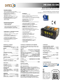
MICRA-D/D6
TACÓMETRO.
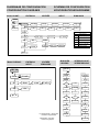
Conformidad CE.
GUIA RÁPIDA DE INSTALACIÓN
GUIDE RAPIDE D’INSTALLATION
QUICK INSTALLATION GUIDE
SCHNELL-INSTALLIERUNGSANLEITUNG
CRONÓMETRO / CONTADOR DE HORAS
• Resoluciones de 4 escalas horarias
• 999s 99 / 100s - 999m 59s - 999h 59m - 99999h
• Cuenta arriba o abajo
• DESPLAZAMIENTO programable (valor inicial)
2 modos de conteo, 2 entradas A y B
• Cuenta mientras la entrada A está activa
• Comienza a contar A, deja de contar B
5 ciclos de funcionamiento, 2 o 4 setpoints
• Comparación permanente de los presets
• Modo encadenado
• Modo en cascada
TACÓMETRO
• Punto decimal programable
• Medición y visualización de rpm, velocidad lineal, flujo.
• Detección del sentido de rotación.
• Medición y visualización del "ciclo de trabajo PWM" (Duty).
• Factor multiplicador / divisor programable (0.0001 a 99999)
2 modos de conteo, 2 entradas A y B
• Unidireccional 1 vía A
• Bidireccional 2 vías separadas A y B
Funciones MIN, MAX
• Las funciones MIN y MAX registran permanentemente los
valores mínimos y máximos de la medición.
Ciclo de funcionamiento, 2 o 4 setpoints
• Comparación permanente de los setpoints, nivel alto
(velocidad más alta) (velocidad más baja)
MEDIDOR DE FRECUENCIA
• Punto decimal programable
• Unidad de visualización Hz
Funciones MIN, MAX
• Las funciones MIN y MAX registran permanentemente
valores mínimos y máximos de la medida.
Ciclo de funcionamiento, 2 o 4 setpoints
• Comparación permanente de presets, nivel alto y bajo.
TOTALIZADOR GENERAL DE IMPULSOS /
HORAS
• Dos informaciones de la misma señal.
Ejemplo: Indicación de flujo y gasto, caso típico en la
medición de la velocidad del fluido y el consumo del mismo.
• 8 dígitos con signo, -99999999 a 99999999
• Punto decimal programable
• Cuenta arriba o abajo
• Factor de conversión de impulso
• Desplazamiento del valor inicial con signo
5 modos de conteo, 2 entradas A y B
• Unidireccional 1 vía A
• Unidireccional 1 vía A + Deja de contar B
• Diferencial de 2 vías A-B
• Bidireccional 1 vía A + Sentido B (arriba / abajo)
• Bidireccional / bidireccional A y B
5 ciclos de funcionamiento, 2 o 4 setpoints
• Comparación permanente de los presets
• Modo encadenado
• Modo en cascada
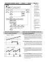
Frecuencia máxima y mínima
Frequencia (min) (Frec / Tac)...………...0.01 Hz
Frequencia (max) (Frec / Tac) ….………. 20 kHz
Frequencia (max) (Totalizador Tac).………8 kHz
Frequencia (max) (Tac modo Duty)…...… 1 kHz
Entrada de conteo
Todas las configuraciones
Sin Totalizador….……………………………...11 kHz
Con Totalizador.………………………………….9 kHz
EXCITACIÓ.……………………....8V DC @ 30mA
20Vdc (no estabilizada) @ 100 mA
Entrada contacto libre
FILTRO
Fc (ton/toff) 50%..................................20 Hz
Fc (ton/toff) 30%..................................10 Hz
ENTRADAS (2 CANALES)
PICK-UP MAGNÉTICO
Sensibilidad..Vin (AC) > 60mVpp @ F < 1kHz
……………...>100 mVpp @ F >1 kHz
NAMUR
Rc.………………………………….3k3 (incorporada)
Ion…………………………………………...< 1mA DC
Ioff..………………………………………….> 3mA DC
TTL/24V DC (encoder)
Nivel lógico......"0" < 2.4V DC, "1" > 2.6V DC
NPN o PNP
Rc.………………………………….3K3 (incorporada)
Nivel lógico…..."0" < 2.4V DC, "1" > 2.6V DC
CONTACTO LIBRE
Vc………………………………………………………...5V
Rc……………………………………………………...3.9K
Fc (activado automáticamente)…………….20Hz
ENTRADA ALTA TENSIÓN (1 CANAL)
CONTADOR Y CRONÓMETRO CON MEMÓRIA
Una E2PROM no volátil retiene todos los datos de pro-
gramación y el valor de conteo cuando se corta o inter-
rumpe la energía.
DISPLAY
Tipo..……………………… dígitos tricolor 14 mm programable
LED's…………………………..8, indicación de estado y control
Punto decimal..………………………………………...programable
Signo.………………………………….automático s/configuración
Indicación sobre escala positiva……..……………………...OvEr
Indicación sobre escala negativa..………………………...-OvEr
Límite display Contador.…..………..Process -99999 a 99999
Totalizador.....………………………..… -99999999 a 99999999
Rango del Cronómetro..…………4, desde 999.99s a 99999h
Rango de Frecuéncia….0.01 Hz a 20KHz/8KHz(totalizador)
Rango Tacómetro…....0 a 99999(rpm), programable (rate)
Factor de escala :
Contador..……...…………....programable de 0.0001 a 99999
Frec/Tacómetro……..………programable de 0.0001 a 99999
Refresco de display
Contador...…………………………………………..…………...100ms
Cronómetro………………………..……………………………..100ms
PRECISIÓN
Frecuencia /Tacómetro..………………...0,005%
Cronómetro..………………………………….0, 01%
Coeficiente temperatura..…………...50 ppm/°C
Tiempo de calentamiento……………..5 minutos
AMBIENTALES
Uso interior
Temperatura de trabajo.…………-10ºC a 60ºC
Temp. de almacenamiento…...-25°C a +85°C
Humedad relativa (no cond.)...< 95% a 40ºC
Altitud máxima………………………………..2000m
MECÁNICA
Dimensiones……...96x48x60mm (DIN 43700)
Orificio en panel………………………….92x45mm
Peso...……………………………………………...200g
Material caja……….Polycarbonate (UL 94 V-0)
Grado de protección frontal…..…………... IP65
Para obtener la declaración de conformidad de
este modelo, entre en nuestro sitio web
www.ditel.es, donde este documento, el manu-
al técnico y otras informaciones de interés
pueden descargarse gratuitamente.
CONTADOR PARCIAL
• Punto decimal programable
• Modo UP, modo DOWN y modo UP / DOWN
• Factor multiplicador / divisor programable (0.0001 a 99999)
• Valor inicial de conteo programable
5 modos de conteo, 2 entradas A y B
• Unidireccional 1 vía A
• Unidireccional 1 vía A + Deje de contar B
• Diferencial de 2 vías A-B
• Bidireccional 1 vía A + Sentido B (arriba / abajo)
• Bidireccional / bidireccional A y B
5 ciclos de funcionamiento, 2 o 4 setpoints
• Comparación permanente de los presets
• Modo encadenado
• Modo en cascada
MODOS DE CONTEO
uP : Cuenta hacia arriba
do : Cuenta hacia abajo
In-A : Entrada “A” cuenta sea cual sea entrada “B”
InA-B : Los pulsos aplicados en la entrada A se suman o
restan al display de conteo si la entrada B está en un nivel
bajo, y se usa como entrada de inhibición
uP-do IndEP : Los pulsos aplicados en la entrada A se
agregan al display de conteo, mientras que los pulsos en
la entrada B se restan
uP-do dIrEC : Cuando la entrada B está en un nivel bajo,
los pulsos aplicados en la entrada A incrementan el con-
teo. Cuando la entrada B está en un nivel alto, los pulsos
en la entrada A disminuyen el conteo
uP-do PHASE : Los flancos ascendentes en la entrada A
incrementan el conteo si la entrada B está en un nivel
bajo. Los flancos descendentes en la entrada A dis-
minuyen la cuenta si la entrada B está en un nivel bajo.
DOWNLOAD
USER MANUAL
De acuerdo con la Directi-
va 2012/19 / UE, no puede
desecharlo al final de su
vida útil como basura
municipal sin clasificar.
Puede devolverlo, sin
ningún costo, al lugar
donde fue adquirido para
proceder a su tratamiento
y reciclaje controlados.

MICRA-D/D6
TACHYMÈTRE
CE Conformity.
GUIA RÁPIDA DE INSTALACIÓN
GUIDE RAPIDE D’INSTALLATION
QUICK INSTALLATION GUIDE
SCHNELL-INSTALLIERUNGSANLEITUNG
CHRONOMÈTRE/COMPTEUR HORAIRE
• 4 Resolutions horaires
• 999s 99/100s - 999m 59s - 999h 59m - 99999h
• Comptage ascendant ou descendent
• OFFSET programmable (valeur du début)
2 modes de comptage, 2 entrées A et B
• Compte lorsque l’entrée A est active
• Démarrer à compter A, arrêter de compter B
5 cycles de fonctionnement, 2 ou 4 seuils
• Comparaison permanente des seuils
• Mode Enchaîné
• Mode Cascade
TACHYMÈTRE
• Position du point décimal programmable
• Mesure et affichage du rpm, vitesse linéale, débit.
• Détectión de la direction de rotation.
• Mesure et affichage du “duty cycle PWM”.
• Facteur multiplicateur ou diviseur programmable
(0.0001 à 99999)
2 modes de comptage, 2 entrées A et B
• Unidirectionel 1 voie A
• Bidirectionel 2 voies separées A et B
Functions MIN, MAX
• Las fonctions MIN, MAX enregistrent en permenence les va-
leurs minimun et máximum de la mesure.
Cycle de fonctionnement, 2 ou 4 seuils
• Comparaison permanente des seuils, niveau élevé
(vitesse supérieure) comme niveau bas (vitesse inférieu-
FREQUENCEMÈTRE
• Position du point decimal programmable
• Unité d’affichage Hz
Fonctions MIN, MAX
• Les fonctions MIN, MAX enregistrent en permanence les
valeurs minimum et maximum de la mesure.
Cycle de fonctionnement, 2 ou 4 seuils
• Comparaison permanente des seuils, niveau élevé et
niveau bas
TOTALISATEUR GÉNÉRAL D’IMPULSIONS
OU D’HEURES
• Deux informations du même signal.
Exemple: Indication du débit et de la consommation.
• 8 digits avec signe, -99999999 à 99999999
• Position du point décimal programmable
• Comptage ascendant ou descendent
• Facteur de conversion des impulsions
• Valeur du debut Offset avec signe
5 modes de comptage, 2 entrées A et B
• Unidirectionel 1 voie A
• Unidirectionel 1 voie A + Stop comptage voie B
• Differentiel 2 voies A-B
• Bidirectionel 1 voie A + Sens B (up/down)
• Bidirectionel 2 voies quadrature A et B
5 cycles de fonctionnement, 2 ou 4 suils
• Comparaison permanente des seuils
• Mode Enchaîné
• Mode Cascade
Fréquences maximales et minimales
Fréquence (min) (Freq / Tach).………...0.01 Hz
Fréquence (max) (Freq / Tach) ………. 20 KHz
Fréquence (max) (Totalisateur Tach).…..8 KHz
Fréquence (max) (Tach mode Duty)...… 1 kHz
Entrée Compteur
Toutes les configurations
Sans Totalisateur……………………………...11 KHz
Avec Totalisateur.……………………………….9 KHz
EXCITATION……………………...8V DC @ 30mA
20Vdc (non stabilisé) @ 100 mA
Entrée Contact libre
FILTRE
Fc avec duty cycle 50%...........................20Hz
Fc avec duty cycle 30%...........................10Hz
ENTRÉES (2 CANAUX)
CAPTEUR MAGNETIQUE
Sensibilité.....Vin (AC) > 60mVpp @ F < 1kHz
……………...>100 mVpp @ F >1 kHz
CAPTEUR NAMUR
Rc...………………………………….3k3 (incorporée)
Ion…………………………………………...< 1mA DC
Ioff……………………………………………………….> 3mA DC
TTL/24V DC (encoder)
Niveaux logiques..."0"<2.4V DC, "1">2.6V DC
CAPTEUR TYPE NPN ou PNP
Rc..………………………………….3K3 (incorporée)
Niveaux logiques..."0"<2.4V DC, "1">2.6V DC
CONTACT LIBRE
Vc………………………………………………………...5V
Rc……………………………………………………...3.9K
Fc (selection auto)……………....…………….20Hz
ENTRÉE HAUTE TENSION (1 CANAL)
MÉMOIRE COMPTEUR ET CHRONO
La mémoire non volatile E2PROM conserve les donées de
programmation et les valeurs de comptage en cas de
coupure de courant.
AFFICHAGE
Type …..………… 5 digits tricolores programmables 14 mm
LED's .………………….8, Indication d’état et programmation
Point décimal ..…………………………………… programmable
Signe ……..…………………. Automatique selon configuration
Indication surechelle positif... … .. …………………… ... OvEr
Indication sur échelle negative....………………………...-OvEr
Plage compteur…………...…..………..Partiel -99999 à 99999
Totalisateur....………………………..… -99999999 à 99999999
Échelles Chronomètre……..…………4, de 999.99s a 99999h
Plage Frequencemètre…...….0.01 Hz à 20KHz/8KHz(Total)
Plage Tachymètre....0 à 99999(rpm), programmable(rate)
Facteur multiplicateur
Compteur.......…………....programmable de 0.0001 à 99999
Freq/Tach……….….……...programmable de 0.0001 à 99999
Cadence de presentation
Compteur...…………………………………………..…………...100ms
Chronomètre..……………………..……………………………..100ms
PRÉCISION
Fréquencemètre /Tachymètre………...0,005%
Chronomètre.………………………………….0, 01%
Coefficient temperature..…………...50 ppm/°C
Temps de chauffe………..……………..5 minutes
ENVIRONNEMENT
Indoor use
Température travail……..…………-10ºC à 60ºC
Température stockage…….…...-25°C à +85°C
Humidité relative (no cond.)....< 95% à 40ºC
Altitude maximale.…………………………..2000m
MÉCANIQUES
Dimensions…..…...96x48x60mm (DIN 43700)
Orifice sur panel………………………….92x45mm
Poids...……………………………………………...200g
Boîtier……….……….Polycarbonate (UL 94 V-0)
Étanchéité frontal…………….…..…………... IP65
COMPTEUR
• Position du point décimal programmable
• Mode UP, mode DOWN et mode UP / DOWN
• Facteur multiplicateur ou diviseur programmable de
0.0001 à 99999)
• Valeur du debut de comptage programmable
5 modes de comptage, 2 entrées A et B
• Unidirectionel 1 voie A
• Unidirectionel 1 voie A + Stop comptage voie B
• Différentiel 2 voies A-B
• Bidirectionel 1 voie A + Sens B (up/down)
• Bidirectionel 2 voies quadrature A et B
5 cycles de fonctionnement, 2 ou 4 seuils
• Comparaison permanente des seuils
• Mode Enchaîné
• Mode Cascade
MODES DE COMPTAGE
uP : Comptage montant
do : Comptage descendant
In-A : Permet le comptage de l’entrée A sans considerer
l’entrée B
InA-B : L’entrée A compte, ou décompte si l’entrée B est
a “0”, en utilisant B comme entrée d’inhibition
uP-do IndEP : L’entrée A compte et l’entrée B décompte
uP-do dIrEC : L’entrée A compte si B est a “0” et dé-
compte si B est a “1”. B s’utilise comme entrée de
direction
uP-do PHASE : A compte sur les flancs positives si B est
a “0” et décompte sur les negatives si B est a “0”
Pour obtenir la déclaration de conformité
correspondant à ce modèle, accédez à notre
site Web www.ditel.es, où ce document, le
manuel technique et d'autres informations
d'intérêt peuvent être téléchargés gratuite-
ment.
DOWNLOAD
USER MANUAL
Selon la Directive 2012/19/
UE, l’utilisateur ne pout se
défaire de cet appareil
comme d’un residu urbain
courant. Vous pouvez le
restituer, sans aucun coût,
au lieu où il a eté acquis
afin qu’il soit procédé à
son traitement et
recyclage contrôlés.

MICRA-D/D6
GUIA RÁPIDA DE INSTALACIÓN
GUIDE RAPIDE D’INSTALLATION
QUICK INSTALLATION GUIDE
SCHNELL-INSTALLIERUNGSANLEITUNG
PARTIAL COUNTER
• Programmable decimal point
• UP mode, DOWN mode and UP / DOWN mode
• Programmable multiplier/divisor factor (0.0001 to 99999)
• Start value of programmable counting
5 counting modes, 2 inputs A and B
• Unidirectional 1 way A
• Unidirectional 1 way A + Stop counting way B
• Differential 2 ways A-B
• Bidirectional 1 way A + Sense B (up / down)
• Two-way bidirectional A and B
5 operating cycles, 2 or 4 presets
• Permanent comparison of the presets
• Chained Mode
• Cascade Mode
CHRONOMETER / HOUR COUNTER
• 4 Hour Resolutions
• 999s 99 / 100s - 999m 59s - 999h 59m - 99999h
• Up or down count
• Programmable OFFSET (start value)
2 counting modes, 2 inputs A and B
• Account while input A is active
• Start counting A, Stop counting B
5 operating cycles, 2 or 4 presets
• Permanent comparison of the presets
• Chained Mode
• Cascade Mode
TACHOMETER
• Programmable decimal point
• Measurement and display of rpm, linear speed, flow
• Detection of direction of rotation
• Measurement and display of "duty cycle PWM".
• Programmable multiplier/divisor factor (0.0001 to 99999)
2 counting modes, 2 inputs A and B
• Unidirectional 1 way A
• Bidirectional 2 separate ways A and B
MIN, MAX functions
• The MIN and MAX functions permanently register the minimum
and maximum values of the measurement.
Operating cycle, 2 or 4 presets
• Permanent comparison of the presets, high level (higher speed)
as low level (lower speed)
FREQUENCY METER
• Programmable decimal point
• Hz display unit
MIN, MAX functions
• The MIN and MAX functions permanently register the
minimum and maximum values of the measurement.
Operating cycle, 2 or 4 presets
• Permanent comparison of presets, level high and low level
GENERAL TOTALIZER OF IMPULSES OR HOURS
• Two information of the same signal.
Example: Indication of Flow and Expense, typical case
in the measurement of fluid velocity and consumption
of same.
• 8 Digits with sign, -99999999 to 99999999
• Programmable decimal point
• Up or down count
• Impulse conversion factor
• Initial value Offset with sign
5 counting modes, 2 inputs A and B
• Unidirectional 1 way A
• Unidirectional 1 way A + Stop counting way B
• Differential 2 ways A-B
• Bidirectional 1 way A + Sense B (up / down)
• Two-way bidirectional A and B
5 operating cycles, 2 or 4 presets
• Permanent comparison of the presets
• Chained Mode
• Cascade Mode
TACHOMETER
CE Conformity.
Maximum and minimum frequency
Frequency (min) (Freq / Tach)………...0.01 Hz
Frequency (max) (Freq / Tach) ………. 20 KHz
Frequency (max) (Totalizer Tach)………..8 KHz
Frequency (max) (Tach mode Duty)...… 1 kHz
Counter input
All configurations
Without Totalizer……………………………...11 KHz
With Totalizer.…………………………………….9 KHz
EXCITATION……………………...8V DC @ 30mA
20Vdc (not stabilized) @ 100 mA
Contact closure input
FILTER
Fc duty cycle 50%...................................20Hz
Fc duty cycle 30%...................................10Hz
INPUTS (2 CHANELS)
MAGNETIC PICKUP
Sensitivity…..Vin (AC) > 60mVpp @ F < 1kHz
……………...>100 mVpp @ F >1 kHz
NAMUR
Rc………………………………….3k3 (incorporated)
Ion…………………………………………...< 1mA DC
Ioff..………………………………………….> 3mA DC
TTL/24V DC (encoder)
Logic levels……."0" < 2.4V DC, "1" > 2.6V DC
NPN or PNP
Rc………………………………….3K3 (incorporated)
Logic levels………..."0" < 2.4V DC, "1" > 2.6V
DC
CONTACT CLOSURE
Vc………………………………………………………...5V
Rc……………………………………………………...3.9K
Fc (activated automatically)..……………….20Hz
COUNTER AND CHRONOMETER MEMORY
Non-volatile E2PROM retains all programming data and
count value when power is removed or interrupted.
DISPLAY
Type…………………...5 programmable tricolor 14 mm digits
LED's……………………………..8, control and status indication
Decimal point………………………………………...programmable
Sign……………………………………….automatic s/configuration
Positive overflow indication…………………………………...OvEr
Negative overflow indication………………………………...-OvEr
Counter display limits………………..Process -99999 to 99999
Totalizer……..………………………..… -99999999 to 99999999
Chronometer ranges………………4, from 999.99s to 99999h
Frequency ranges…………0.01 Hz to 20KHz/8KHz(totalizer)
Tachometer range...0 to 99999(rpm), programmable(rate)
Scale factor
Counter..……………....programmable from 0.0001 to 99999
Freq/Tach……………...programmable from 0.0001 to 99999
Display update rate-
Counter………………………………………………..…………...100ms
Chrono..……………………………..……………………………..100ms
ACCURACY
Frequency/Tachometer..………………...0,005%
Chronometer.………………………………….0, 01%
Temperature coefficient..…………...50 ppm/°C
Warm up time……………………………..5 minutes
ENVIRONMENTAL
Indoor use
Operating temp….…………………-10ºC to 60ºC
Storage temperature..………...-25°C to +85°C
Relative humidity (non cond.).< 95% at 40ºC
Max altitude…..………………………………..2000m
MECHANICAL
Dimensions………...96x48x60mm (DIN 43700)
Panel cutout……………………………….92x45mm
Weight……………………………………………...200g
Case material………Polycarbonate (UL 94 V-0)
Frontal protection degree…………………... IP65
To obtain the declaration of conformity correspond-
ing to this model enter our website www.ditel.es ,
where this document, the technical manual and
other information of interest can be downloaded
freely.
COUNT MODES
uP : Up count
do : Down count
In-A : Allows count on A input regardless of input B
InA-B : Pulses applied at the A input are added or sub-
tracted to the count display if the B input is at low level
and being used as inhibited input
uP-do IndEP : Pulses applied at the A input are added to
the count display while pulses at the B input are subtrac-
ted
uP-do dIrEC : When B input is at low level, the pulses
applied at the A input increment the count. When B input
is at high level, the pulses at the A input decrement the
count
uP-do PHASE : The rising edges at the A input increment
the count if the B input is at low level. The falling edges at
the A input decrement the count if the B input is at low
level.
DOWNLOAD
USER MANUAL
According to 2012/19/EU
Directive, You cannot dispose
of it at the end of its lifetime
as unsorted municipal waste.
You can give it back, without
any cost, to the place where
it was adquired to proceed to
its controlled treatment and
recycling.

MICRA-D/D6
GUIA RÁPIDA DE INSTALACIÓN
GUIDE RAPIDE D’INSTALLATION
QUICK INSTALLATION GUIDE
SCHNELL-INSTALLIERUNGSANLEITUNG
ZÄHLER
• Programmierbarer Dezimalpunkt
• UP-Modus, DOWN-Modus und UP / DOWN-Modus
• Programmierbarer Multiplikator / Divisor-Faktor
(0,0001 bis 99999)
• Startwert der programmierbaren Zählung
5 Zählmodi, 2 Eingänge A und B.
• Unidirektionaler 1 Kanal A.
• Unidirektionaler 1 Kanal A + Stopp-Zählkanal B.
• Differential 2 Kanäle A-B
• Bidirektionale 1 kanal A + B Sense (up / down)
• Zwei-Kanäle bidirektional A und B
5 Betriebszyklen, 2 oder 4 Sollwerte
• Permanenter Vergleich der Sollwerte
• Verketteter Modus
• Kaskadenmodus
ZEITMESSER / STUNDENZÄHLER
• 4 Stunden Auflösungen
• 999s 99 / 100s - 999m 59s - 999h 59m - 99999h
• Aufwärts- oder Abwärtszählung
• Programmierbarer OFFSET (Startwert)
2 Zählmodi, 2 Eingänge A und B.
• Konto während der Eingang A aktiv
• Start Zählen A, Stop-Zählung B
5 Betriebszyklen, 2 oder 4 Sollwerte
• Permanenter Vergleich der Sollwerte
• Verketteter Modus
• Kaskadenmodus
DREHZAHLMESSER
• Programmierbarer Dezimalpunkt
• Messung und Anzeige von Drehzahl, Lineargeschwindigkeit,
Durchfluss
• Erfassen der Drehrichtung
• Messung und Anzeige der PWM "Duty Cycle"
• Programmierbarer Multiplikator/Divisor-Faktor (0,0001 bis 99999)
2 Zählmodi, 2 Eingänge A und B.
• Unidirektionaler 1 Kanal A
• Bidirektionale 2 separate Kanal A und B
MIN, MAX Funktionen
• Die MIN und MAX-Funktionen registrieren permanent die
Minimal- und Maximalwerte der Messung.
Betriebszyklus, 2 oder 4 Sollwerte
• Permanenter Vergleich der Voreinstellungen, hoher Pegel (höhere
FREQUENZMESSER
• Programmierbarer Dezimalpunkt
• Hz Anzeigeeinheit
MIN, MAX Funktionen
• Die MIN und MAX-Funktionen registrieren permanent die
Minimal- und Maximalwerte der Messung.
Betriebszyklus, 2 oder 4 Sollwerte
• Permanenter Vergleich von Sollwert, hohem und nie
drigem Pegel
TOTALISIERER VON IMPULSEN ODER
STUNDEN
• Zwei Informationen des gleichen Signals.
Beispiel: Anzeige von Durchfluss und Ausstoß mit
Messung der Geschwindigkeit der Flüssigkeit und ihres
Verbrauchs
• 8 Ziffern mit Vorzeichen, -99999999 bis 99999999
• Programmierbarer Dezimalpunkt
• Aufwärts- oder Abwärtszählung
• Impulsumrechnungsfaktor
• Anfangswert Offset mit Vorzeichen
5 Zählmodi, 2 Eingänge A und B.
• Unidirektionaler 1 Kanal A.
• Unidirektionaler 1 Kanal A + Stopp-Zählkanal B
• Differential 2 Kanäle A-B
• Bidirektionale 1 kanal A + B Sense (up / down)
• Zwei-Kanäle bidirektional A und B
5 Betriebszyklen, 2 oder 4 Sollwerte
• Permanenter Vergleich der Sollwerte
• Verketteter Modus
• Kaskadenmodus
DREHZAHLMESSER
CE-Konformität
Maximale und minimale Frequenz
Frequenz (min) (Freq/Drehzälh)………...0.01 Hz
Frequenz (max) (Freq/Drehzähl) ………. 20 KHz
Frequenz (max) (Totalisator Drehzähl)…..8 KHz
Frequenz (max) (Drehzähl Duty)……....… 1 kHz
Zählereingang
Alle Konfigurationen
Ohne Totalisator.……………………………...11 KHz
Mit Totalisator.…………………………………….9 KHz
Speisung……….…………………...8V DC @ 30mA
20Vdc (nicht stabilisiert) @ 100 mA
Kontaktschließungseingang
FILTER
Fc Arbeitszyklus 50%...............................20Hz
Fc Arbeitszyclus 30%...............................10Hz
EINGÄNGE (2 KANÄLE)
MAGNETISCHER AUFNEHMER
Empfindlichkeit..Vin (AC)>60mVpp @ F<1 kHz
………………..>100 mVpp @ F >1 kHz
NAMUR
Rc………………………………….3k3 (Incorporated)
Ion…………………………………………...< 1mA DC
Ioff..………………………………………….> 3mA DC
TTL/24V DC (Encoder)
Logikpegel.……."0" < 2.4V DC, "1" > 2.6V DC
NPN oder PNP
Rc………………………………….3K3 (Incorporated)
Logikpegel..…..."0" < 2.4V DC, "1" > 2.6V DC
KONTAKTSCHALTER
Vc………………………………………………………...5V
Rc……………………………………………………...3.9K
Fc (automatisch aktiviert).....……………….20Hz
HOCHSPANNUNGSEINGANG (1 KANAL)
ZÄHLER UND TIMER
Der nichtflüchtige E2PROM-Speicher speichert die Program-
mierdaten und die Zählwerte bei einem Stromausfall.
ANZEIGE
Typ ………… 5 dreifarbige programmierbare Ziffern 14 mm
LED's ………………….8, Statusanzeige und Programmierung
Dezimalpunkt …………………………………… programmierbar
Polarität .…………………. Automatisch je nach Konfiguration
Positive Überlaufanzeige…………..……………………… ... OvEr
Negative Überlaufanzeige….………………………………...-OvEr
Grenzwerte für die Zähleranzeige...Proc. -99999 bis 99999
Totalisator...………………………..… -99999999 bis 99999999
Chronometerbereiche.……………4, von 999.99s bis 99999h
Frequenzbereiche.…….0.01 Hz bis 20KHz/8KHz(totalisator)
Drehzahlmesserbereich…. 0 bis 99999(U/min), prog.(rate)
Skalierungsfaktor
Zälhler....……………....programmable von 0.0001 bis 99999
Freq/Drehzähl………...programmable von 0.0001 bis 99999
Aktualisierungsrate anzeigen
Zähler..………………………………………………..…………...100ms
Chrono…..…………….....……………………………..………..100ms
Frequenz/Drehzählmesser ...….programmable 0.1 bis 9.9s
GENAUIGKEIT
Frequenz / Drehzahlmesser..…………...0,005%
Zeitmesser…..………………………………….0, 01%
Temperaturkoeffizient.....…………...50 ppm/°C
Aufwärmzeit...……………………………..5 minuten
MILIEUBEDINGT
Innengebrauch
Betriebstemperatur.………………-10ºC bis 60ºC
Lagertemperatur.….....………..-25°C bis +85°C
R.Luftfeuchtigkeit(nicht kond)< 95% bei 40ºC
Max Höhe….…..………………………………..2000m
MECHANISCH
Abmessungen..…...96x48x60mm (DIN 43700)
Schalttafel-Ausschnitt………….……….92x45mm
Gewicht..…………………………………………...200g
Gehäusematerial...…Polycarbonat (UL 94 V-0)
Frontalschutzgrad………...…………………... IP65
Für die Konformitätserklärung für dieses Modell
finden Sie auf unsere Website www.ditel.es wo
dieses Dokument, die technische Anleitung und
weitere Informationen von Interesse heruntergela-
den werden können.
ZÄHLMODI
uP : Aufwärtszählstand
do : Rückwärtszählsignalen
In-A : Ermöglicht das Zählen auf A-Eingang unabhängig
von Eingang B.
InA-B : Impulse am Eingang A hinzugefügt oder auf die
Zählanzeige subtrahiert, wenn der B-Eingang auf einem
niedrigen Pegel ist, und als Eingang verwendet werden
inhibierten
uP-do IndEP : Impulse am Eingang A werden auf die
Zählanzeige hinzugefügt, während Impulse am B-Eingang
subtrahiert
uP-do dIrEC : Wenn B-Eingang auf niedrigem Pegel ist,
aufgetragen die Impulse am Eingang A inkrementieren die
Zählung. Wenn B-Eingang auf hohem Pegel ist, verringern
sich die Impulse am Eingang A des Zählwerts
uP-do PHASE : Die ansteigenden Flanken an den A-
Eingang inkrementieren die Zählung, wenn der B-Eingang
auf niedrigem Pegel ist. Die abfallenden Flanken an den A-
Eingang dekrementiert die Zählung, wenn der B-Eingang
auf niedrigem Pegel ist.
DOWNLOAD
USER MANUAL
Gemäß der Richtlinie 2012/19/EU
können Sie es am Ende seiner
Lebensdauer nicht als
unsortierten Siedlungsabfall
entsorgen. Sie können es
kostenlos an dem Ort
zurückgeben, an dem es
erworben wurde, um es einer
kontrollierten Behandlung und
Wiederverwertung zuzuführen.

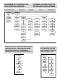
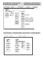
DIAGRAMAS DE CONFIGURACIÓN SCHÉMAS DE CONFIGURATION
CONFIGURATION DIAGRAMS KONFIGURATIONSDIAGRAMME
p r o c n 1 n p
- 1 - - 3 -
- 2 -
8 8 8 8
node
d o
u p
c o u n t c h r o n f r e c
c n d s p s e t p a n o u t r s o u t l o g 1 n
5 t o r e
p r o
1 n d e p d 1 r e c
- 4 - - 5 - - 6 - - 7 -
t a c h
undo
1 n a 1 n a b p h a s e
h r
u p
1 n a b1 n a
c h r o n
n s s
- p r o -
0 . o 1 sh n n
d o
Mode COUNT: ENTRADA ENTRÉE INPUT EINGANGS
INPUT TYPE
1 10 to 300 V ac
2 Magnetic pickup
3 NAMUR sensor
4 PNP sensor
5 NPN sensor
6 TTL/ 24 V Encoder
7 Contact closure
8888
c o d e
p r o
l 1 s t
t o t l c
s e t 1
s e t 2
s e t 3
s e t 4
1nput
d s p
c o l o r
r u n
c h a n g
----
s t o r e
spval
r s o u t
anout
l o g 1 n
r e s p
nahnn
s t o r e
r e s t
BLOQUEO VERROUILLAGE
LOCKING VERRIEGELUNG.
Code?
0 / 1 ? ≠ - - - - ?
0 : Desbloqueado / Déverrouillé
Unlocked / Freigeschaltet
1: Bloqueado / Verrouillé
Locked / Ausgesperrt
Mode CHRONO: ENTRADA ENTRÉE
INPUT EINGANGS

DIAGRAMAS DE CONFIGURACIÓN SCHÉMAS DE CONFIGURATION
CONFIGURATION DIAGRAMS KONFIGURATIONSDIAGRAMME
8 8 8 . 8 8
r p nd e c p r a t e
f r e c
d 1 r
1 n p
- p r o -
1 n v
0 0 0 0 . 1
d u t y
l 1n
ppr
00001
d e c p
8 8 8 8 . 8
p r o
1np1
0 0 0 . 1
- p r o -
t a c h
0 0 0 0 . 1
d s p
0 0 0 0 . 1
0 0 0 0 . 1
1 n p
0 0 0 0 . 1
0 0 0 0 . 1
d s p 1
0 0 0 0 . 1
0 0 0 0 . 1
1 n p 2
0 0 0 0 . 1
d s p 2
0 0 0 0 . 1
d s p 1
0 0 0 0 . 1
0 0 0 0 . 1
1np2
1 0 0 . 0
d s p 2
0 0 0 0 . 1
t l 1 n
0 1 . 0
- p r o -
Mode FREQ/TACH: ENTRADA ENTRÉE INPUT EINGANGS
RESTAURACIÓN DE LA CONFIGURACIÓN DE FÁBRICA
RESTAURATION DE LA CONFIGURATION D'USINE
RESTORATION OF FACTORY CONFIGURATIO
WIEDERHERSTELLUNG DER FABRIKKONFIGURATION
0 0
l o a d 1 n
- p r o -
r u n
- p r o -
< 3s
> 3s
74
<3s
88888
s e t 2
s e t 1
p r o
88888
s e t 4
88888
88888
s e t 3
s t o r e
ACCESO DIRECTO A SETPOINT
ACCÈS DIRECT À CONSIGNE
DIRECT ACCESS TO SETPOINT
DIRECT ACCESS TO SOLL

DIAGRAMAS DE CONFIGURACIÓN SCHÉMAS DE CONFIGURATION
CONFIGURATION DIAGRAMS KONFIGURATIONSDIAGRAMME
d e c p
88888.
t o t a lp r o c
c n d s p
o f f s
±00000
8 8 .8 8
f d 1 u
- p r o -
f a c t
00001
00001.
yes
node
d 1 s p l
br1ght
n o
p r o
f n u l t
h 1 l o
c o l o r
r u n r u n
r u n
p r o gp r o g p r o g
red green amber
eco
- o n - - o f f -
1 0
r e l a b s
d e c p
88888.
o f f s
10000
±h0000
t o t a l
t o t a l t o t a l
Mode COUNT : DISPLAY AFFICHAGE DISPLAY ANZEIGEN
f a c t
00001
t o t a lp r o c
c n d s p
yes
1 n d e p
00001.
t a v g
8 8 .8 8
t l 1 n
- p r o -
0 . 1
0 1 . 0
d 1 s p l
br1ghtn o
h 1 l o
c o l o r
r u n r u nr u n
p r o gp r o g p r o g
red green amber
eco
- o n - - o f f -
1 0
- p r o -
- p r o -
node
r e l a b s
d e c p
88888.
o f f s
l 0000
±h0000
8 8 .8 8
f d 1 u
- p r o -
f a c t
00001
00001.
f n u l t
d 1 r e c p h a s e
t o t a lt o t a l t o t a l
Mode FREC/TACH : DISPLAY AFFICHAGE DISPLAY ANZEIGEN
“TOTAL” is not available on “FREC” and “DUTY mode”

- o f f -
p r o c
s e t 1 s e t 2
s e t p
- o n -
- p r o -
- h 1 -
- h y s -
- p r o -
88888
n o c h
s e t 3 s e t 4
- l o -
- d l y -
8 8
a l a r n
red green amber
a l a r n a l a r n
±8888
- l o 2 -
t o t a l
l 8888
±h8888
node
1 n d e p
- h 1 -
l a t c h
r eset st op cl ear cscde
- l o -
p u l s e
0 . 1
t r a c k
±88888
Mode FREC/TACH : RELÉS RELAIS RELAYS RELAYS
SET2
SET1
0 or
Offset
OUT1
Latch
Modo Lo
OUT2
Pulse 1s
SET2
SET1
0 or
Offset
OUT1
Pulse 1s
OUT2
Latch
Modo Hi
SET2
SET1
0 or
Offset
OUT1
Pulse 1s
Mode 1
OUT2
SET2
SET1
0 or
Offset
OUT1
Pulse
1s
Modo 1
OUT2
Latch
Modo 3
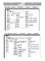
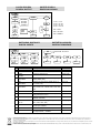
MODO DE OPERACIÓN DE RELÉ MODE DE FONCTIONNEMENT DU RELAIS
RELAY OPERATION MODE RELAISBETRIEBSMODUS
Mode 1 : INDEP Mode 2 : RESET
Mode 3 : STOP
The complete programming of only one of the Setpoints is shown, it is
the same for the rest
Track mode only available on Set2

SET3 / SET4
-Solo con opción
4RE, 4OP/OPP ó
función lógica #10
-Seulement avec
option 4RE, 4OP /
OPP ou fonction logi-
que # 10
-Only with option
4RE, 4OP / OPP or
logical function # 10
-Nur mit Option 4RE,
4OP / OPP oder lo-
gischer Funktion # 10
- o f f -
p r o c
s e t 1 s e t 2
s e t p
- o n -
- p r o -
- p r o -
n o c h
s e t 3 s e t 4
a l a r n
red green amber
a l a r n a l a r n
±8888
t o t a l
l 8888
±h8888
node
1 n d e p
- h 1 -
l a t c h
r eset st op cl ear cscde
- l o -
p u l s e
0 . 1
t r a c k
±88888
Mode COUNT / CHRONO : RELÉS RELAIS RELAYS RELAYS
SET1
SET4
0 or
Offset
OUT4
Latch
Mode 1
OUT1
SET2
SET1
0 or
Offset
OUT1
Pulse 1s
Mode 5
OUT2
Pulse 1s
Mode 5
Mode 4 : CLEAR
Mode 5 : CASCADE
-Modo Track solo
disponible en SET2 y
SET4
-Mode Track unique-
ment disponible en
SET2 et SET4
-Track mode only
available in SET2 and
SET4
-Track-Modus nur in
SET2 und SET4 ver-
fügbar
MODO DE ACTUACIÓN HI / LO / LO2: En el modo HI, la salida se
activa cuando el valor de la pantalla excede el nivel del punto de
ajuste y en el modo LO, la salida se activa cuando el valor de la
pantalla cae por debajo del punto de ajuste, en el modo LO2 evita
que durante la conexión de ali,mentación entre con la alarma
activada y espera exceder el punto de ajuste una vez para actuar
como en modo LO
MODE D'ACTION HI / LO / LO2: En mode HI, la sortie s'active lorsque
la valeur d'affichage dépasse le niveau de consigne et en mode
LO, la sortie s'active lorsque la valeur d'affichage tombe en des-
sous du point de consigne, en mode LO2, cela évite que pendant
la mise sous tension , il entre avec l'alarme activée et attend de
dépasser une fois le point de consigne pour agir comme en mode
LO
HI/ LO / LO2 ACTING MODE: In HI mode, the output activates when
the display value exceeds the setpoint level and in LO mode, the
output activates when the display value falls below the setpoint, in
LO2 mode it avoids that during the power-up it enters with the
alarm activated and waits to exceed the setpoint once to act as in
LO mode
HI / LO / LO2-AKTIONSMODUS: Im HI-Modus wird der Ausgang aktiv-
iert, wenn der Anzeigewert den Sollwert überschreitet, und im LO-
Modus wird der Ausgang aktiviert, wenn der Anzeigewert unter
den Sollwert fällt. Im LO2-Modus wird vermieden, dass während
des Einschaltvorgangs Nach oben tritt es mit aktiviertem Alarm ein
und wartet darauf, den Sollwert einmal zu überschreiten, um wie
im LO-Modus zu wirken
MODO DE OPERACIÓN DE RELÉ MODE DE FONCTIONNEMENT DU RELAIS
RELAY OPERATION MODE RELAISBETRIEBSMODUS

DIAGRAMAS DE CONFIGURACIÓN SCHÉMAS DE CONFIGURATION
CONFIGURATION DIAGRAMS KONFIGURATIONSDIAGRAMME
t o t a lp r o c
c n d s p
o f f s
±00000
- p r o -
yes
d 1 s p l
br1ght
n o
p r o h 1 l o
c o l o r
r u n r u n
r u n
p r o gp r o g p r o g
red green amber
eco
- o n - - o f f -
1 0
d e c p
88888.
o f f s
l 0000
h 0 0 0 0
t o t a l
t o t a l t o t a l
- p r o -
- p r o -
Mode CHRONO : DISPLAY AFFICHAGE DISPLAY ANZEIGEN
out l o
anout
±88888
out h1
p r o
±88888
out l o
anout
±88888
out h1
p r o
±88888
p r o c t ot al
out l o
l 0000
h0000
out h1
l 0000
h0000
p r o
SALIDA ANALÓGICA SORTIE ANALOGIQUE ANALOG OUTPUT ANALOGE AUSGABE
(*)
(**)
(*) Display for 10V / 20mA output
(**) Display for 0V / 4mA output
Sin totalizador Sans totalisateur
Without totalizer Ohne Totalisator
Con totalizador Avec totalisateur
With totalizer Mit Totalisator

Según la Directiva 2012/19/UE, no puede deshacerse de este aparato como un residuo urbano normal. Puede devolverlo, sin coste alguno, al lugar donde fue adquirido para que de esta forma se proceda a su
tratamiento y reciclado controlados.
Selon la Directive 2012/19/UE, l’utilisateur ne pout se défaire de cet appareil comme d’un residu urbain courant. Vous pouvez le restituer, sans aucun coût, au lieu où il a eté acquis afin qu’il soit procédé à son
traitement et recyclage contrôlés.
According to 2012/19/EU Directive, You cannot dispose of it at the end of its lifetime as unsorted municipal waste. You can give it back, without any cost, to the place where it was adquired to proceed to its contro-
lled treatment and recycling.
Gemäb der Richtlinie 2012/19/EU darf dieses Elektronikgerät nicht über den herkömlichen Haushaltsmüllkreislauf entsorgt werden. Sie kann das Gerät kostenlos an die Stelle von der es erworben wurde, für die
kontrollierte Bearbeitung und Wiederverwertung zurückgeben.
baud
rsout
1200
adr
p r o
8 8
2400
4800
9600
19200
t rans
pr t 2
pr t 3
dl y
prt 1
p r o
1
2
3
4
p r o
SALIDA RS2/RS4 SORTIE RS2/RS4
RS2/RS4 OUTPUT RS2/RS4 AUSGANG
RS4 ?
1np- 1 1np- 2
l og1n
1np- 3
8 8 8 8 8 8
p r o p r o p r o
ENTRADAS DIGITALES ENTRÉES LOGIQUES
DIGITAL INPUTS DIGITALE EINGÄNGE
Nº Function Description Activation
0 Deactivated None None
1 OFFSET Take the value of the display as offset Falling edge
2 RESET
OFFSET
Reset the offset memory Falling edge
3 RESET
VARIABLES
Resets the value of the variable (ProC,
totAL, PEAK, VAL) Falling edge
4 SEE
VARIABLES
Displays the value of the variable (ProC, to-
tAL, PEAK, VAL)
Low level
5 PRINT
VARIABLES
Send in ASCII the value of the variable (ProC,
totAL, PEAK, VAL, OFFSEt, SEt1, Set2, Set3,
Set4
Falling edge
6 HOLD Fix the display value Low level
7 BRIGHTNESS Changes the brightness of the display alter-
nating between Hi and Lo
Low level
8 COLOR Change the color of the display (RED,
GREEN, ORANGE)
Low level
9 SETPOINT/OFFSET
VALUE
Presents the value to program in (OFFSEt,
SEt1, SEt2, SEt3, SEt4)
Falling edge
10 FALSE SETPOINT Simulates that the instrument has a four set-
points option installed
Low level
11 REMOTE KEYBOARD InP1 = ENTER, InP2 = SHIFT, InP3 = UP Low level
12 START/STOP Start / Stop Chronometer in A mode,
or Stop Counter / Totalizer
Low level
Prt1= ASCII
Prt2= ISO 1745
Prt3= MODBUS
1: dLY = 0 ms
2: dLY = 30 ms
3: dLY = 60 ms
4: dLY = 100 ms
proc t ot al
03
peak
p r o p r o p r o
val
p r o
FUNCTION Nº 03 & 04

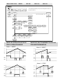
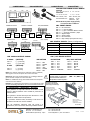
Orificio en panel
Orifice dans le pannea
Panel cutout
Schalttafel-Ausschnitt
92 x 45 mm
Estanqueidad frontal
Étanchéité du frontal
Frontal protection degree
Frontplatte Schutzart
IP65
Dimensiones y montaje
Dimensions et montage
Dimensions and mounting
Abmessungen und Montage
CN2 CN3
CN1
CN7 CN5 CN4
CN6
WIRING and POWER SUPPLY RANGE
MICRA-D
85 V – 265 V AC 50/ 60 Hz to 100 – 300 V DC
MICRA-D6
22 – 53 V AC 50/ 60 Hz to 10,5 - 70 V DC
PIN 1: Phase / VDC PIN 2: Neutral / VDC
Recommended fuse : MICRA-D (0.5A)
MICRA-D6 (2A)
NOTE: When DC power supply polarity
in connector CN1 is indistinct.
1 2 1 8 1 4
PIN (INPUT) Function Number
PIN 1 COMMON
PIN 2 (INP-1) RESET PROCES Function nº 3 (PROC)
PIN 3 (INP-2) RESET TOTALIZER Function nº 3 (TOTAL)
PIN 4 (INP-3) HOLD Function nº 6
CN3 DIGITAL INPUTS (Factory Configuration)
4 1
5 2
6 3
1
2
CN4 ANALOG OUTPUT SIGNAL
4-20mA (OPTION)
PIN 1 = (-) [4-20 mA]
PIN 2 (+) [4-20 mA]
0-10V (OPTION)
PIN 1 = (-) [0-10V]
PIN 2 = (+) [0-10V]
CN6 / CN7 RELAIS OUTPUT
2RE OPTION 4RE OPTION 4OP/4OPP OPTION
PIN 1 = NO1
PIN 2 = COMM1
PIN 3 = NC1
PIN 4 = NO2
PIN 5 = COMM2
PIN 6 = NC2
PIN 1 = RL1
PIN 2 = RL2
PIN 3 = RL3
PIN 4 = RL4
PIN 5 = N/C
PIN 6 = COMMON
PIN 1 = OPTO1
PIN 2 = OPTO2
PIN 3 = OPTO3
PIN 4 = OPTO4
PIN 5 = N/C
PIN 6 = COMMON
Fusible Relé recomendado :
Fusible Relais recommandé :
Recommended Relais fuse :
Empfohlene Sicherungrelais :
** IMPORTANTE! / IMPORTANT! / WICHTIG!
Para garantizar la seguridad eléctrica de acuerdo con EN
61010-1 deberá instalarse como medida de protección un
fusible externo.
Pour garantir le sécurité électrique selon EN 61010-1 il faut
installer un fusible externe de protection.
To guarantee electrical safety according to EN 61010-1 a
protective external fuse must be installed.
Um die elektrische Sicherheit nach EN 61010-1 zu
garantieren, muss eine externe Sicherung installiert werden.
20210304 30728794
DISEÑOS Y TECNOLOGÍA, S.A.
Xarol, 6B P.I. Les Guixeres
08915 Badalona (Barcelona) - Spain
Tel. +34 933 394 758
Fax +34 934 903 145
Email: dtl@ditel.es ; web: www.ditel.es
Nota: Para obtener información adicional sobre el cableado,
descargue el manual completo de nuestro sio web
Remarque: Pour plus d'informaons sur le câblage, téléchar-
gez le manuel complet sur notre site Web
Note: For addional wiring informaon download complete
manual from our website
Hinweis: Für zusätzliche Informaonen zur Verkabelung laden
Sie das vollständige Handbuch von unserer Website herunter
(2RE = 8A / 4RE = 5A)
CONEXIONADO RACCORDEMENT CONNECTIONS ANSCHLÜSSE
CN2 INPUT SIGNAL
PIN 1 = No Connection
PIN 2 = (+) 20V Excitation
PIN 3 = (+) 8,2 V Excitation Namur sensors
PIN 4 = (-) Common excitation / input
PIN 5 = Signal B input
PIN 6 = Signal A input
PIN 7 = No Connection
PIN 8 = High voltage input (300 Vac max.)
CN2
1 8
MAGNETIC PICKUP
Secondary
Principal
CN2
1 8
CONTACT CLOSURE
Secondary
Principal
CN2
1 8
PNP/ NPN SENSOR
Exc Out Comm Exc Out Comm
1
CN2
8
NAMUR sensor
Secondary
Principal
CN2
1 8
ENCODER
EXC COMM OUTB OUTA
CN2
10- 300 (only 1 input)
-
 1
1
-
 2
2
-
 3
3
-
 4
4
-
 5
5
-
 6
6
-
 7
7
-
 8
8
-
 9
9
-
 10
10
-
 11
11
-
 12
12


in anderen Sprachen
- français: Ditel MICRA-D
- español: Ditel MICRA-D
Verwandte Artikel

Andere Dokumente
-
Pepperl+Fuchs KC-LCD-24-24VDC Bedienungsanleitung
-
-
Eaton E5524E0402 Operating Instructions Manual
-
-
-
Eaton Electrical MN05401014E Benutzerhandbuch
-
Baumer NE216 Installation and Operating Instructions
-
-
-