Peavey SMRTM 821a Benutzerhandbuch
- Kategorie
- Zusätzliche Musikausrüstung
- Typ
- Benutzerhandbuch
Dieses Handbuch eignet sich auch für


2
Intended to alert the user to the presence of uninsulated “dangerous voltage” within the product’s
enclosure that may be of sufficient magnitude to constitute a risk of electric shock to persons.
Intended to alert the user of the presence of important operating and maintenance (servicing)
instructions in the literature accompanying the product.
CCAAUUTTIIOONN::Risk of electrical shock — DO NOT OPEN!
CCAAUUTTIIOONN::To reduce the risk of electric shock, do not remove cover. No user serviceable parts inside.
Refer servicing to qualified service personnel.
WWAARRNNIINNGG::To prevent electrical shock or fire hazard, do not expose this appliance to rain or moisture.
Before using this appliance, read the operating guide for further warnings.
Este símbolo tiene el propósito, de alertar al usuario de la presencia de “(voltaje) peligroso” sin
aislamiento dentro de la caja del producto y que puede tener una magnitud suficiente como para
constituir riesgo de descarga eléctrica.
Este símbolo tiene el propósito de alertar al usario de la presencia de instruccones importantes sobre la
operación y mantenimiento en la información que viene con el producto.
PPRREECCAAUUCCIIOONN::Riesgo de descarga eléctrica ¡NO ABRIR!
PPRREECCAAUUCCIIOONN::Para disminuír el riesgo de descarga eléctrica, no abra la cubierta. No hay piezas útiles
dentro. Deje todo mantenimiento en manos del personal técnico cualificado.
AADDVVEERRTTEENNCCIIAA::Para evitar descargas eléctricas o peligro de incendio, no deje expuesto a la lluvia o
humedad este aparato Antes de usar este aparato, Iea más advertencias en la guía de operación.
Ce symbole est utilisé dans ce manuel pour indiquer à l’utilisateur la présence d’une tension dangereuse
pouvant être d’amplitude suffisante pour constituer un risque de choc électrique.
Ce symbole est utilisé dans ce manuel pour indiquer à l’utilisateur qu’il ou qu’elle trouvera d’importantes
instructions concernant l’utilisation et l’entretien de l’appareil dans le paragraphe signalé.
AATTTTEENNTTIIOONN::Risques de choc électrique — NE PAS OUVRIR!
AATTTTEENNTTIIOONN::Afin de réduire le risque de choc électrique, ne pas enlever le couvercle. Il ne se trouve à
l’intérieur aucune pièce pouvant être reparée par l’utilisateur. Confiez I’entretien et la réparation de
l’appareil à un réparateur Peavey agréé.
AAVVEERRTTIISSSSEEMMEENNTT: Afin de prévenir les risques de décharge électrique ou de feu, n’exposez pas cet
appareil à la pluie ou à l’humidité. Avant d’utiliser cet appareil, lisez attentivement les avertissements
supplémentaires de ce manuel.
Dieses Symbol soll den Anwender vor unisolierten gefährlichen Spannungen innerhalb des Gehäuses
warnen, die von Ausreichender Stärke sind, um einen elektrischen Schlag verursachen zu können.
Dieses Symbol soll den Benutzer auf wichtige Instruktionen in der Bedienungsanleitung aufmerksam
machen, die Handhabung und Wartung des Produkts betreffen.
VVOORRSSIICCHHTT:: Risiko — Elektrischer Schlag! Nicht öffnen!
VVOORRSSIICCHHTT:: Um das Risiko eines elektrischen Schlages zu vermeiden, nicht die Abdeckung enfernen. Es
befinden sich keine Teile darin, die vom Anwender repariert werden könnten. Reparaturen nur von
qualifiziertem Fachpersonal durchführen lassen.
AACCHHTTUUNNGG::Um einen elektrischen Schlag oder Feuergefahr zu vermeiden, sollte dieses Gerät nicht dem
Regen oder Feuchtigkeit ausgesetzt werden. Vor Inbetriebnahme unbedingt die Bedienungsanleitung lesen.
2

3
IIMMPPOORRTTAANNTT SSAAFFEETTYY IINNSSTTRRUUCCTTIIOONNSS
WWAARRNNIINNGG::When using electrical products, basic cautions should always be followed, including the following:
1. Read these instructions.
2. Keep these instructions.
3. Heed all warnings.
4. Follow all instructions.
5. Do not use this apparatus near water.
6. Clean only with a dry cloth.
7. Do not block any of the ventilation openings. Install in accordance with manufacturer’s instructions.
8. Do not install near any heat sources such as radiators, heat registers, stoves or other apparatus (including amplifiers)
that produce heat.
9. Do not defeat the safety purpose of the polarized or grounding-type plug. A polarized plug has two blades with one
wider than the other. A grounding type plug has two blades and a third grounding plug. The wide blade or third prong is
provided for your safety. If the provided plug does not fit into your outlet, consult an electrician for replacement of the
obsolete outlet.
10. Protect the power cord from being walked on or pinched, particularly at plugs, convenience receptacles, and the point
they exit from the apparatus.
11. Note for UK only: If the colors of the wires in the mains lead of this unit do not correspond with the terminals in your
plug‚ proceed as follows:
a) The wire that is colored green and yellow must be connected to the terminal that is marked by the letter E‚ the earth
symbol‚ colored green or colored green and yellow.
b) The wire that is colored blue must be connected to the terminal that is marked with the letter N or the color black.
c) The wire that is colored brown must be connected to the terminal that is marked with the letter L or the color red.
12. Only use attachments/accessories provided by the manufacturer.
13. Use only with a cart, stand, tripod, bracket, or table specified by the manufacturer, or sold with the apparatus. When a
cart is used, use caution when moving the cart/apparatus combination to avoid injury from tip-over.
14. Unplug this apparatus during lightning storms or when unused for long periods of time.
15. Refer all servicing to qualified service personnel. Servicing is required when the apparatus has been damaged in any
way, such as power-supply cord or plug is damaged, liquid has been spilled or objects have fallen into the apparatus,
the apparatus has been exposed to rain or moisture, does not operate normally, or has been dropped.
16. Never break off the ground pin. Write for our free booklet “Shock Hazard and Grounding.” Connect only to a power
supply of the type marked on the unit adjacent to the power supply cord.
17. If this product is to be mounted in an equipment rack, rear support should be provided.
18. Exposure to extremely high noise levels may cause a permanent hearing loss. Individuals vary considerably in
susceptibility to noise-induced hearing loss, but nearly everyone will lose some hearing if exposed to sufficiently
intense noise for a sufficient time. The U.S. Government’s Occupational and Health Administration (OSHA) has specified
the following permissible noise level exposures:
Duration Per Day In Hours Sound Level dBA, Slow Response
890
692
495
397
2 100
1
1
⁄
2
102
1 105
1
⁄
2
110
1
⁄
4
or less 115
According to OSHA, any exposure in excess of the above permissible limits could result in some hearing loss. Ear plugs or protectors to the
ear canals or over the ears must be worn when operating this amplification system in order to prevent a permanent hearing loss, if exposure
is in excess of the limits as set forth above. To ensure against potentially dangerous exposure to high sound pressure levels, it is
recommended that all persons exposed to equipment capable of producing high sound pressure levels such as this amplification system be
protected by hearing protectors while this unit is in operation.
SSAAVVEE TTHHEESSEE IINNSSTTRRUUCCTTIIOONNSS!!

4
The SMR™821a is a professional microphone and line level audio program mixer intended for
fixed installation applications. This single‚ rack-mount unit is designed to provide high-quality
audio performance using versatile control options and a simple user-interface. Engineered from
the ground up with the commercial sound systems contractor in mind‚ the SMR 821a includes
many features for easy operation‚ installation and servicing.
With three independent audio output buses‚ the SMR 821a is perfect for applications where
zoned output and simple monitoring is required. Six of the eight inputs include high-quality
microphone pre-amplifiers and separate gain controls. Additional rear panel controls provide
even more flexibility for proper gain setup‚ output assign and remote control features.
In stand-alone applications‚ the SMR 821a is a very powerful tool. Ease of use‚ external control
options and a simple user-interface make it perfect for many applications where the end-user
must have access to the audio system. The ability to link multiple units provides even more
flexibility for a wide range of applications.
This manual describes the features of the SMR 821a and how it can fit into a variety of
applications.
DDeessccrriippttiioonn::
EENNGGLLIISSHH
FFeeaattuurreess::· single rack space design
· eight total inputs: 6 balanced mic/line; 2 unbalanced stereo
· LED level/clip status indicator on each channel
· mic inputs include selectable 48-volt phantom power
· two selectable stereo line inputs (mono or stereo switchable)
· three assignable electronically-balanced outputs: Left‚ Right‚ Aux
· master level controls for each output bus
· three 5-segment LED meter arrays
· 4-band EQ: low‚ low-mid‚ high-mid‚ high
· integral channel muting system with priority
· audio and mute bus linking
· Left‚ Right‚ Aux and Mute bus links for stacking multiple units
· rear panel master/slave linking mode switch
· remote master Left/Right level control port
· rear panel 20 dB pad switch on each microphone input
· front panel continuously variable preamp gain control
· rear panel bus assign switches for each microphone channel
· rear panel global 100 Hz low-cut filter switch for all microphone inputs
· mute bus with channel 1 rear panel threshold control
· select switch for routing microphone mix bus post remote control
‚ all audio I/O on removable Euro-type connectors

5
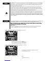
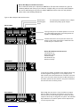
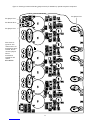
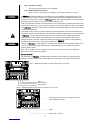
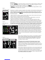
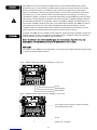
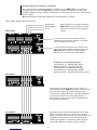
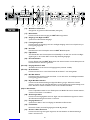
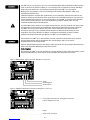
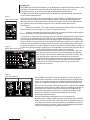
FFrroonntt PPaanneell
1 4 7 9
2 5 12 138103
611 14
(1) Gain Control
This control may also be referred to as a trim control. It varies the amount of mic preamp
gain at the first gain stage.
(2) Status LED
This bi-color LED illuminates green when a -20 dBu signal is present and red when the signal
level is near clipping.
(3) Level Control (Channels 1–6)
This control adjusts the channel signal level sent to the mix buses. It functions identically on
channels 1–6.
(4) Level Control (Channels 7–8)
This level control adjusts the stereo signal sent to the mix buses for channels 7 & 8
(5) Select
The Select switch is a momentary switch that selects the stereo input signal from either chan-
nel 7 or 8. When power is applied to the SMR™821a‚ channel 7 is selected by default.
(6) Select LED
The LEDs indicate which stereo input channel (7 or 8) is feeding the mix buses.
(7) Low EQ
The Low EQ is a shelving-type active tone control. (±15 dB @ 70 Hz)
(8) Low Mid EQ
The Low Mid EQ is a bandpass (peak/notch) type of active tone control. (±15 dB @ 250 Hz)
(9) Hi Mid EQ
The Hi Mid EQ is a bandpass (peak/notch) type of active tone control. (±15 dB @ 3.1 kHz)
(10) Hi EQ
The Hi EQ control is a shelving type of active tone control. (±15 dB @ 10kHz)
(11) Level Meters
The three 5-segment LED Level Meters monitor the levels of the Left‚ Right and Aux outputs.
The 0 dB reference level corresponds to +4 dBu at its respective output connector.
(12) Left Level
The Left Level control adjusts the level of the Left output.
(13) Right Level
The Right Level control adjusts the level of the Right output.
(14) Aux Level
The Aux Level control adjusts the output of the Aux output.
(15) Power LED
This LED indicates that AC power is applied to the SMR 821a.
15

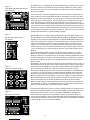
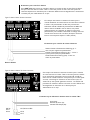
6
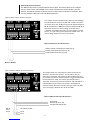
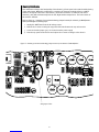
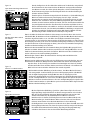
RReeaarr PPaanneell
16 18 2321
17 19 20 22 2624
(16) AC Power Receptacle
Accepts standard IEC power cable (included).
(17) Power Switch
Applies power to the SMR™821a.
(18) Left‚ Right and Aux Outs
Main mix bus balanced outputs.
(19) Remote Connector
Used to control signal levels of the Left and Right outputs and Stereo Input Select from a
remote location.
(20) Bus Links
Stacking connector for linking multiple SMR™821a mixers.
(21) EQ Switch
Places the 4-band equalizer in or out of the Left and Right signal paths. In the Out position the
equalizer is completely bypassed.
(22) Bus Link Switch
For use with multiple SMR™821a units. This switch places the mixer in the master or slave
mode of operation.
(23 & 24) Channels 7 & 8 Input
Dual RCA connectors for stereo input sources (nominally -10 dBV).
(25 & 26) Mode Switch
Selects either stereo or mono mode for channels 7 or 8.
(27) Mic Mix Switch
Allows the summed signal of channels 1–6 to be routed before or after the remote Left/Right
volume control.
(28) Right Out Mute Switch
Controls the muting of the Right mix bus. When this switch is enabled‚ the Left and Right mix
buses are affected by the activity of the muting circuit. When this switch is defeated‚ only the
Left bus is affected.
(29) Low Cut Switch
This low cut filter switch has a corner frequency of 100 Hz. Enabling this switch affects
channels 1–6 only.
(30) Assignment Switches
Assigns the input channel to the Left‚ Right or Aux mix buses and enables the 48-volt phantom
power for channels 1–6.
(31) Channels 1–6 Input
Balanced microphone or line input on removable Euro-type connector.
(32) Pad Switch
The Pad switch attenuates the input signal by 20 dB.
(33) Channel 1 Mute Threshold
Adjusts the level of signal needed to trigger the muting circuitry in Channel 1.
25 27 30
28 29 31 32 33

7
IInnssttaallllaattiioonn
CCoonnnneeccttiioonnss
The SMR™821a is designed to be installed in a standard EIA equipment rack. Since the depth of the
unit is only 8 3⁄4"‚ you can use practically any size rack. Using only a single EIA rack space‚ the SMR
821a includes integral rack mounting ears and does not require any additional hardware for rack
mounting…other than rack screws!
All connections are made on the rear panel. It is recommended that you provide an additional 4" of
clearance between the rear of the chassis and the interior rear of your equipment rack for wiring
harnesses. Since every connection to the SMR 821a is easy to disconnect‚ the unit can be removed
from an equipment rack easily‚ without having to disturb fixed wiring harnesses.
Using common sense when installing this unit will help ensure that it will provide years of trouble-
free service. In installations where there are multiple power amplifiers‚ it is also recommended that
the SMR 821a be located more towards the top of the rack‚ while power amplifiers remain near the
bottom. This is generally considered standard rack design in the commercial audio industry. Following
this convention will ensure adequate rack cooling‚ proper weight distribution and reliable operation
from the SMR 821a.
Connecting the SMR 821a is not much different than any other analog audio device. In addition to the
normal inputs and outputs‚ there are also external control ports and bus link connectors.
NNoottee:: AAllll ccaabblleess ffoorr tthheessee ccoonnnneeccttiioonnss sshhoouulldd bbee sshhiieellddeedd.. RReeffeerr ttoo tthhee ffoolllloowwiinngg
iilllluussttrraattiioonnss ffoorr eeaacchh ttyyppee ooff ccoonnnneeccttiioonn..
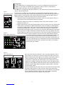
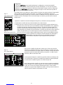
Audio Inputs
The inputs to the SMR 821a are balanced. This means there are three wires for each connection:
positive; negative and shield. These should be connected to each pin accordingly.
Figure 1. Balanced Audio Input Connections: Microphone or Line Level
Shield
Audio Negative
Audio Positive
Insert jumper wire between the negative and shield
pins for unbalanced circuits
Figure 2. Unbalanced Audio Input Connections: Microphone or Line Level
Shield
Audio “Hot” or Positive

8
Figure 3. RCA Input Connections
Left Shield
Left “Hot” Audio
Right Shield
Right “Hot” Audio
The Mode switch selects either Stereo mode or Mono mode
individually for channel 7 or 8. In Stereo mode‚ the Left input
signal feeds the Left mix bus and the Right input signal feeds the
Right mix bus via the front panel Level control. In Mono mode‚
the summed Left and Right signals feed both the Left and Right
mix buses. This allows for only one input to be used to feed
stereo mix buses. Additionally‚ it allows for Left and Right
outputs of the source to be summed without a Y-cable. In
either mode‚ a summed mono signal feeds the Aux mix bus.
The cabling for these connectors should be of the standard‚ consumer unbalanced shielded type. If you are using a 2-
conductor shielded cable‚ make sure to connect the negative side of the signal to the shield. Note: Unbalanced signal
sources should be located within approximately 6' of the SMR™821a.
Stereo Inputs
Channels 7 and 8 provide two inputs for each channel. These are intended for stereo use‚ as each
input (Left‚ Right) has a fixed assignment to the Left and Right output buses. Additionally‚ a sum of
both inputs is fed simultaneously to the Aux output bus. Although you cannot change the distribution
of these inputs‚ you can determine if they are stereo or mono. The Mode switch‚ when enabled‚ will
sum both connectors‚ feeding both to the Left and Right outputs simultaneously. These connectors
accept nominal levels of -10 dBV.

9
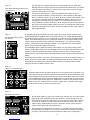
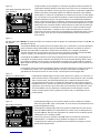
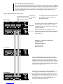
Figure 4. Master Output & Bus Link Connections
Audio Positive
Audio Negative
Shield
In a linked system‚ the Master mixer’s outputs
would be the primary system outputs.
The EQ switch places the 4-band equalizer in or out of
the Left and Right signal paths. In the Out position the
equalizer is completely bypassed.
The Bus Link switch is used to place the mixer in the
master or slave mode of operation. A stand-alone unit
should always be in master mode.
To increase the number of available inputs‚ multiple mixers may
be linked together. Linking mixers is a very simple process.
Wire the Bus Links connections between each mixer. Select the
mixer to be used as the master and place its Bus Link Switch in
the Master position. All other mixers in the system should have
their link switches in the Slave position.
Even though only one mixer is set up as a Master‚ an output
from any mixer in the linked system may be used. Since the
buses are linked‚ all of the input signals are routed to all of the
outputs to which they are assigned in the system. The individual
EQ and Master Level controls operate the local output levels
on each respective mixer.
Master Bus & Mute Link Connections
Left Audio Link (L)
Right Audio Link (R)
Link Shield (Shd)
Aux Audio Link (A)
Mute Bus Link (M)
Master Mixer
Slave Mixer 1
Slave Mixer 2
Master Bus Output and Link Connections
These connections allow you to expand your SMR™821a. The Bus Links connector has 5 pins for
combining multiple units. Using a 4-pin conductor‚ shielded cable‚ you can easily connect between
two or more units wiring pin-to-pin across multiple SMR™821a mixers. Note: Use only shielded
cables. Refer to the following illustrations.

10
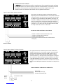
External Control Connections
The SMR™821a provides a powerful external control option. This feature allows you to configure
remote controls for the Left and Right Level controls simultaneously and the Channel 7/8 select
function. The Remote operation connector provides a simple way to make these connections. Note:
Use only shielded cable. Refer to the following illustrations.
This example is used to simultaneously control the Left and Right
Level Controls from a remote location with a simple connection
on the back of the unit. A 10k pot will provide approximately 0 to
30 dB of attenuation. A 100k pot will provide about 0 to 60 dB of
attenuation. If desired‚ a control voltage can be inserted to
“command” attenuation instead of a pot. This voltage is inserted
into the “C” input and is positive referenced to SHD. Note: The
control voltage should never exceed 11 volts DC.
This example shows the connection for remote selection of the
Channels 7 or 8 input select feature. The selection is done by
connecting a momentary switch between SEL and SHD. Each time
the switch is activated‚ the channel selection is toggled and alternated
between Channel 7 and 8. This remote operation functions in
conjunction with the front panel Select Control. A bi-color LED or 2
individual LEDs may be connected as shown in the diagram for
remote indication of the selected stereo line input. Note: The IND
circuit can supply a maximum of 6 mA for the LEDs.
Remote Volume Control Connections
Remote Channel 7/8 Select Connections
Remote Volume
Volume Control to Potentiometer CCW Leg (V)
Control to Potentiometer Wiper Leg (C)
Shield Potentiometer CW Leg (Shd)
Shield (Shd)
Channel 7/8 Select (Sel)
Indicator LED Output (Ind)
CH 7/8
Select
Switch
CH 7/8 Select LEDs
CH 8
CH 7
Figure 5. Remote Volume Control Connections
Figure 6. Remote Channel 7/8 Select Connections

11
Configuration
Since the SMR™821a is an analog product‚ there is not a lot of configuration to worry about. No
software‚ no data cables‚ no networks and no headaches. However‚ there are a few things to
remember while you begin to use your new SMR™821a mixer.
The SMR™821a is shipped from the factory ready to go. You should be able to follow the steps below
and get audio through the unit.
The first step is to calibrate your gain settings for the inputs. Each microphone input has a Gain
Control and a Level Control. These controls work together while the Status LED and the master Level
Meters provide a visual indication of the control’s behavior. To properly adjust the SMR™821a for
optimal performance‚ follow these simple steps for each input channel:
1. Adjust the Channel‚ Left‚ Right and Aux Level Controls so they are at the midpoint. There is a
center detent on the control which indicates this position.
2. Adjust the channel Gain Control to its minimum position—fully counter-clockwise—for the
channel you want to set.
3. Apply an audio signal to the input by either playing a line level audio source or by speaking into
a microphone at a nominal level. While monitoring the master Level Meters‚ slowly adjust the
Gain Control clockwise while audio is present. Keep turning the control until the Level Meters
are indicating nominal level—around the -6 dB to 0 dB area on the meters. In addition‚ the
channel Status LED should be green—not red. The bi-color Status LED illuminates green when a
signal is present at -20 dBu. It illuminates red when the signal level is near clipping. The Level
Control adjusts the signal level sent to the mix buses. This control should be operated near the
mid-point of its travel to assure an optimized signal-to-noise ratio and maximize headroom‚
once the Gain Control is properly set. If you find that the input signal is too
hot and you cannot properly adjust the Gain Control without causing a
clipping condition‚ you will need to use the Pad Switch‚ located on the rear
panel. This switch will give you an additional 20 dB of pad beyond what the
front panel Gain Control provides. Follow this procedure for each input to
ensure proper gain structure.
Figure 7.
Input Channel Controls
Figure 8.
Master Meters and Controls
Figure 9.
Stereo Input Channels There is no Gain Control for channels 7 and 8. To properly adjust the gain on
these channels‚ you will need to control the output level of the audio source.
With the Channel Level and the Master Level controls at the detent position‚ a -
1o dBV signal will present a +4 dBu output at the Bus Output connectors.
It is important to adjust the gain down enough so the preamp will not clip at
louder levels. Carefully consider the type of audio source and adjust the gain
settings accordingly. Material with wide dynamic range will generally require a
lower gain control setting‚ while material that is fairly constant‚ can usually
tolerate a higher setting.
After these adjustments are made‚ make sure you monitor the front panel LEDs
and meters during normal use. Take note of the action of the Status LEDs.
Under normal operation‚ you should see lots of green with an occasional flash
of red. Constant red‚ however‚ indicates that a gain setting is improperly
adjusted and should be reset using the above procedure.

12
The next step is to configure the many rear panel switches for your applications.
Although the unit is shipped from the factory with default switch values‚ you should
make sure that these settings are correct for your application. Let’s take a look at
each one and describe how it works.
First there are the Channels 1–6 Bus Assign Switches (See Figure 10). These
switches provide the ability to assign each input to the Left‚ Right or Aux output
buses. In addition‚ you can turn on or off the phantom power on each channel. There
is a single 8-position DIP switch for each TWO input channels. Take care you are
adjusting the correct switch for each channel. It is recommended that you use a
small screwdriver or other instrument to set the switches. Do not force the switches.
Also‚ keep in mind that the ON position is UP. Figure 10 shows the DIP switches with
all functions in the ON position. Note: The factory setting is all bus assign switches
ON and phantom OFF.
Figure 10.
Input Channel Bus Assign Switches and
Input Connectors
Figure 11.
Mic Mix‚ Rt Out Mute and Low
Cut Switches
Figure 12.
Channel 7 & 8 Mode Switches
Figure 13.
EQ and Bus Link Switches
In approximately the middle of the rear panel‚ you will find a group of three switches. They
include the Mic Mix‚ Rt Out Mute and Low Cut switches (Figure 11). The Mic Mix switch allows
the summed signal of Channels 1–6 to be routed before or after the remote Left/Right volume
control. In the Pre Remote position‚ the signals from Channels 1–6 are affected by the remote
volume control along with the stereo input from either Channel 7 or 8. In the Post Remote
position‚ only the stereo input from either Channel 7 or 8 is affected by the remote volume
control. The factory default setting is Pre Remote.
The Rt Out Mute switch controls the muting of the right bus mix. The factory setting of this
switch is Enable. When enabled‚ the Left and Right mix buses are affected by the activity of the
Channel 1 muting circuit. When this switch is defeated‚ only the Left bus is affected by the
muting circuit. Use the Channel 1 Mute Threshold control to set the trigger point to activate the
muting.
The Low Cut switch enables a filter with a corner frequency of 100 Hz and is helpful to filter out
rumble‚ wind noise‚ breath thumps and other low-frequency signals that rob amplifier power
and muddy the mix. Enabling this switch will affect Channels 1–6 only. The factory default
setting for the Low Cut switch is Defeat or Flat.
The Mode switch (Figure 12) selects either Stereo mode or Mono mode for Channel 7 or 8.
In the Stereo mode‚ the Left input signal feeds the Left mix bus and the Right input signal
feeds the Right mix bus via the front panel Level control. In the Mono mode‚ the summed
Left and Right input signals feed Left and Right mix buses. This allows for a mono source
to be used to feed the stereo mix buses. Additionally‚ it allows for Left and Right outputs
of the source to be summed without a Y-cable. In either mode‚ a summed mono signal
feeds the Aux mix bus. The factory default is Stereo.
The EQ switch (Figure 13) places the 4-band stereo equalizer in or out of the Left and
Right signal paths. In the OUT position the equalizer is completely bypassed. The
factory default is IN. The Bus Link switch is used to place the mixer in the master or
slave mode of operation. A stand-alone unit should always be in the master mode
and the factory default is Master. See the Connections section of this manual for
details on Bus Linking and using multiple units.
That completes the configuration. As you can see‚ the SMR™821a provides many
powerful features for better‚ more cost-effective systems. The multiple combinations
of routing‚ control and input assignment facilitate a wide range of applications.

13
OOppttiioonnaall FFeeaattuurreessThe SMR™821a offers optional features for specific applications. These options include transformers
for the microphone inputs and the ability to defeat the functionality of the Channel 7/8 select switch.
These options and modifications require access to the inside of the SMR™821a. It highly
recommended that the installation of the optional microphone transformers and modification of the
Channel 7/8 Select switch be performed by qualified service personnel. There are dangerous voltages
present inside the unit as well as static sensitive components. Damage to the SMR™821a internal
circuitry caused by an unqualified persons is not covered under warranty‚ and in fact‚ could void the
warranty altogether.
IInnssttaalllliinngg tthhee OOppttiioonnaall MMiiccrroopphhoonnee IInnppuutt TTrraannssffoorrmmeerrss
Optional transformers for use with the microphone input circuits are available from Peavey Electronics
Corp. (part # 70500852). The optional transformers may be added one at a time‚ all at once‚ or in any
combination. To ensure that the transformers are properly installed‚ please refer to the instructions
and illustrations in this section. If you have any questions or are not sure about the correct procedure‚
do not hesitate to call our Tech Support Group.
Refer to Figure 14‚ “Cutaway of circuit board showing jumper locations for installation of optional
microphone transformers” while performing the following steps:
1. Unplug the SMR™821a from the AC voltage source.
2. Remove the 6 screws securing the top panel. Remove the top and set aside.
3. Remove the 5 screws securing the rear panel to the chassis.
4. Remove the 5 screws securing the front panel to the chassis.
5. Carefully turn the unit upside down.
6. Remove the 11 screws securing the circuit board assembly to the chassis.
7. Carefully turn the entire unit right side up. One end of the circuit board assembly (with the front
and rear panels still attached) can be lifted out of the chassis with power supply wires still intact
to access the bottom side of the circuit board.
8. Locate the 6 round transformer outlines.
9. Before installing the transformers‚ you will need to cut some jumpers and resistors. These
components are labeled with reference designators on the board.
10. For each transformer installed‚ 3 jumpers and 1 resistor will need to be cut. The following table
shows which components need to be cut for their corresponding transformer.
Transformer T101 T1201 T301 T401 T501 T601
Components J102 J103 J202 J203 J302 J303 J402 J403 J502 J503 J602 J603
to be cut J105 R116 J205 R216 J305 R316 J405 R416 J505 R516 J605 R616
11. The transformers can only be inserted into the board one way. Place a transformer into the
circuit board and solder in place.
Repeat process for each transformer being installed.
Re-installing the Circuit Board and Re-assembling the Unit
1. Place the circuit board assembly (with the front and rear panels still attached) into the chassis.
2. Carefully turn the unit upside down and replace the 11 screws securing the circuit board
assembly to the chassis.
3. Carefully turn the unit right side up.
4. Replace the 5 screws securing the front panel to the chassis.
5. Replace the 5 screws securing the rear panel to the chassis.
6. Place the top panel on the chassis and replace the 6 screws securing it to the chassis.

14
Cut Jumper Here
Cut Resistor Here
Cut Jumper Here
Note: Cuts are
typical for each
channel where the
transformers will be
installed. Do not
cut these jumpers
unless a
transformers
installed for that
channel.
BE CAREFUL!
Cut Jumper Here
Figure 14. Cutaway of circuit board showing jumper locations for installation of optional microphone transformers.

15
Cut Jumper Here
Figure 15. Cutaway of circuit board showing jumper location of the Channel 7/8 Modification
CChhaannnneell 77//88 MMooddiiffiiccaattiioonn
This modification changes the functionality of the Channel 7/8 front panel select switch and the busing
of the audio inputs. When this modification is complete‚ the front panel switch will act as a MUTE
switch for all signals connected to the Channel 7 and 8 RCA connectors. In addition‚ both stereo
channels (7 & 8) will simultaneously feed the Left‚ Right and Aux output buses. The Select action of
the switch is defeated.
Refer to Figure 15‚ “Cutaway of circuit board showing jumper location for Channel 7/8 Modification”
while performing the following steps:
1. Unplug the SMR™821a from the AC voltage source.
2. Remove the 6 screws securing the top panel of the unit. Remove the top and set aside.
3. Locate and cut the jumper J905. It is located near the power supply.
4. Place the top panel on the chassis and replace the 6 screws securing it to the chassis.

16
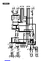
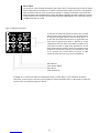
BBlloocckk DDiiaaggrraamm
RIGHT
LEFT
R MUTE
CTRL
Threshold
Detection
CTRL
CH 8
LEVEL
RIGHT
CH 7
LEVEL
HPF
CH 2
LEVEL
L MUTE
GAIN
Mute
Threshold
Level
LEFT
CH 1
LEVEL
SIG/
CLIP
GAIN
RIGHT OUT
MUTE
PREAMP
PREAMP
SIG/
CLIP
HPF
CH 3
CH 4
CH 5
CH 6
SIG/
CLIP
SIG/
CLIP
CH 2
+48V
CH 1
CH 8
CH 7/8
SELECT
CH 7MONO
RIGHT
OUTPUT LEVEL
L
AUX
MASTER
LEVEL
LEFT
MIC MIX
+V
R
EQ
BYPASS
VCA
AUX
OUTPUT LEVEL
V
SEL
M
C
RIGHT
OUTPUT
FOUR BAND EQUALIZER
LEFT
OUTPUT LEVEL
AUX
OUTPUT
FOUR BAND EQUALIZER
VCA
LEFT
OUTPUT
R MUTE
CTRL
CTRL
L MUTE
A
IND
CH 7
L
R
AUX
AUX
HPF
CTRL
-1
MONO
CH 8
L
R
+48V LOW CUT PRE
REMOTE
POST
REMOTE
BUS LINK
BUS
LINKS
+
-
+
-
+
-
+
-
-
+
REMOTE
-1
Cut to mix
CH 7 & 8
Optional
Transformer
CTRL
Optional
Transformer
PAD
PAD
SHD
SHD
RIGHT
I
I
I

17
SSppeecciiffiiccaattiioonnss
DDiimmeennssiioonnss
1.75" (H) x 19" (W) x 8.75" (D) (45mm x 483mm x 222mm)
WWeeiigghhtt
7.4 lbs (3.4 kg)
MMoouunnttiinngg
Single EIA Rack Mount
CCoonnnneeccttiioonnss
Removable Euro-type connectors for single channel audio inputs‚ outputs‚ bus link and external control. RCA single-ended female
for channels 7 and 8 stereo inputs. IEC receptacle for AC power.
TTeesstt CCoonnddiittiioonnss
120Vac 60 Hz maintained throughout testing.
0 dBu = 0.775 Vrms
0 dBV = 1.00 Vrms
* Min. input level (sensitivity) is the smallest signal that will produce a nominal output with controls set at maximum gain.
** Nominal settings are defined as all controls set at center detent for nominal output. Microphone gain control is as specified.
0 dBu = 0.775 Vrms
0 dBm = 1 mW
IInnppuutt SSeennssiittiivviittyy
OOuuttppuuttss
Input
Output Minimum Load
Impedance
Output Level
Nominal Maximum
Balanced/
Unbalanced Connector
Microphone
without pad
Left
Right
Aux
600 ohms
600 ohms
+4 dBu
+4 dBu
+21 dBu
+19 dBm
+21 dBu
+19 dBm
balanced
balanced
+
-
ground
+
-
ground
Microphone
with pad
2k
2k
2k
2k
10k
Max Gain +60 dB
Min Gain +10 dB
Max Gain +40 dB
Min Gain -10 dB
Max Gain +60 dB
Min Gain +20 dB
Max Gain +40 dB
Min Gain 0 dB
N/A
-76 dBu
-25 dBu
-56 dBu
-5 dBu
-74 dBu
-34 dBu
-54 dBu
-14 dBu
-20 dBu
-56 dBu
-4 dBu
-36 dBu
+16 dBu
-54 dBu
-14 dBu
-34 dBu
+6 dBu
-10 dBu
-39 dBu
+13 dBu
-19 dBu
+33 dBu
-37 dBu
+3 dBu
-17 dBu
+23 dBu
+7 dBu
balanced
balanced
balanced
balanced
unbalanced
+
-
ground
+
-
ground
+
-
ground
+
-
ground
RCA jacks
Microphone
without pad (optional
transformer)
Microphone
with pad (optional
transformer)
Stereo Line
Input
Impedance
(Ohms)
Input Gain
Pot Setting
Input Level: dBu
Min* Nom** Max
Balanced/
Unbalanced Connector

18
NNooiissee
Output Signal/Noise (typical) Test Conditions
Left
Right
GGaaiinn
Mic input range without pad:
Mic input to output without pad:
Mic input range with pad:
Mic input to output with pad:
Mic input range without pad (optional transformer):
Mic input to output without pad (optional transformer):
Mic input range with pad (optional transformer):
Mic input to output with pad (optional transformer):
10 dB to 60 dB
80 dB max
-10 dB to 40 dB
60 dB max
20 dB to 60 dB
80 dB max
0 dB to 40 dB
60 dB max
Aux
100 dB
84 dB
80 dB
95 dB
92 dB
81 dB
All level controls down
Master level controls nominal
Channel level controls down
All controls nominal
All channels assigned
Mic gain minimum
All level controls down
Master level control nominal
Channel level controls down
All controls nominal
All channels assigned
Mic gain minimum
FFrreeqquueennccyy RReessppoonnssee
20 Hz–20 kHz +0 dB/-1 dB
TToottaall HHaarrmmoonniicc DDiissttoorrttiioonn PPlluuss NNooiissee
<0.05% typical 22 Hz–22 kHz BW; Mic to Left/Right out
40 dB Mic gain‚ +4 dBu‚ 20 Hz–20 kHz
EEqquuiivvaalleenntt IInnppuutt NNooiissee ((EEIINN))
-128 dBu Mic input terminated with 150 ohms
CCoommmmoonn MMooddee RReejjeeccttiioonn RRaattiioo ((MMiicc IInnppuutt))
>70 dB typical 20 Hz–20 kHz
CCrroossssttaallkk AAddjjaacceenntt CChhaannnneellss ((11 kkHHzz))
>70 dB typical
CCrroossssttaallkk OOuuttppuutt ttoo OOuuttppuutt ((11 kkHHzz))
>60 dB typical
PPhhaannttoomm PPoowweerr
+48 volts at mic + and - inputs
RReemmoottee CCoonnttrrooll VVoolluummee
30 dB attenuation (10k ohm potentiometer) typical
60 dB attenuation (100k ohm potentiometer) typical
CChhaannnneell MMuuttee
>60 dB attenuation
SSiiggnnaall//CClliipp IInnddiiccaattoorrss
Input Channel Status
Green: -20 dBu
Red: 2 dB below clipping
Output Level Meters
-24: -20 dBu
-6: -2 dBu
0: +4 dBu
+6: +10 dBu
Clip: 2 dB below clipping
PPoowweerr RReeqquuiirreemmeennttss
Domestic: 120 Vac‚ 60 Hz 15 watts nominal
Export: 230 Vac‚ 50/60 Hz 15 watts nominal

19
La SMMRR™™882211aaes una mezcladora de audio para señales de línea y de micrófono diseñada para
aplicaciones que requieren instalaciones permanentes. Esta unidad de un espacio de rack
provee gran calidad de audio usando versátiles opciones de control y una interfase fácil de usar.
Pensada desde el principio con el contratista de sistemas de audio comerciales en mente, la
SSMMRR 882211aaincluye muchas características para su fácil operación, instalación y servicio.
Con tres buses de salida de audio independientes, la SSMMRR 882211aaes perfecta para aplicaciones
que necesitan salidas por zonas y requieren monitoreo simple. Seis de las ocho entradas
incluyen preamplificadores de micrófono de alta calidad con controles de ganancia separados.
Controles adicionales en la parte trasera proveen aún más flexibilidad de ganancia, asignación
de salidas y funciones de control remoto.
En aplicaciones variadas la SSMMRR 882211aaes una herramienta poderosa. Fácil manejo, opciones de
control externas y una interfase sencilla la hacen perfecta para muchas aplicaciones en las que
el usuario tiene que tener acceso al sistema de audio. La habilidad de conectar unidades
múltiples da aún más flexibilidad para un rango de usos más amplio.
Este manual describe las funciones de la SSMMRR 882211aay cómo puede funcionar en una variedad de
aplicaciones.
DDeessccrriippttiioonn::
CCaarraacctteerrííssttiiccaass· Diseño de un espacio de rack
· Total de ocho salidas: 6 balanceadas mic/line, 2 no balanceadas estéreo
· Indicador LED e saturación en cada canal
· Entradas de micro incluyen 48-voltios de poder phantom seleccionable
· Dos entradas de nivel de línea estéreo (seleccionable mono/estéreo)
· Tres salidas electrónicamente balanceadas asignables: Izquierda, Derecha, Aux
· Controles de nivel maestros para cada bus de salida
· Tres medidores de LED de 5 segmentos
· EQ de cuatro bandas: graves, medios graves, medios agudos y agudos.
· Sistema de muteo de canales integral con prioridad
· Encademaniemto de audio y muteo de busses
· Posibilidad de interconexión de Izq. Der. Aux y Mute para múltiples unidades
· Interruptor de modo esclavo/maestro en parte trasera
· Puerto de control remoto para nivel maestro Izq./Der.
· Interruptor de pad de 20 dB en cada entrada de micro en la parte posterior
· Control de ganancia de variación constante del preamp en el panel frontal
· Selectores de asignación de bus para canales de micro en la parte trasera
· Filtro de recorte de graves de 100 Hz para todas las entradas de micrófono en la parte trasera
· Bus de muteo con control de umbral del canal 1 en la parte posterior
· Interruptor de selección para mandar el bus de micros post control remoto
· Todas las entradas/salidas con conectadores removibles Euro-Type.
EESSPPAAÑÑOOLL

20
PANEL FRONTAL
1 4 7 9
2 5 12 138103
611 14
(1) Control de Ganancia
Este controlaría la cantidad de ganancia de preamplificador de micrófono en este primer
paso de ganancia.
(2) LED de Estatus
Este LED bicolor se ilumina verde cuando hay una señal de -20 dBu presente y rojo cuando
el nivel de señal está cerca de saturar.
(3) Control de Nivel (Canales 1-6)
Este control ajusta el nivel de señal del canal que se envía al bus de mezcla. Funciona de
manera idéntica en los canales 1-6.
(4) Control de Nivel (Canales 7-8)
Este control ajusta el nivel de señal estéreo que se envía a los buses de mezcla 7 y 8.
(5) Selección
El interruptor de selección es un interruptor momentáneo que selecciona entre la señal de
entrada estéreo del canal 7 u 8. Cuando se aplica corriente a la SMR 821a, el canal 7 está
preseleccionado.
(6) LED de selección
Este LED indica el canal de entrada estéreo (7 u 8) que está alimentando el bus de mezcla.
(7) EQ Grave
El EQ grave es activo de tipo shelving (±15 dB @ 70 Hz).
(8) EQ Grave Medio
El EQ de medios graves es activo de tipo de paso de banda (±15 dB @ 250 Hz)
(9) EQ Agudo Medio
El EQ agudo medio es activo de tipo shelving (±15 dB @ 3.1 kHz)
(10) EQ Agudo
El EQ agudo es activo de tipo shelving (±15 dB @ 10 kHz)
(11) Medidores de Nivel
Los tres medidores de nivel de LEDs de 5 segmentos monitorean los niveles de las salidas
Izquierda, Derecha y Aux. La referencia de 0 dB corresponde a +4 dBu en su respectivo
conectador de salida.
(12) Nivel Izquierdo
El control de Nivel Izquierdo ajusta el nivel de la salida Izquierda.
(13) Nivel Derecho
El control de Nivel Derecho ajusta el nivel de la salida Derecha.
(14) Nivel Aux
El control de Nivel Aux ajusta el nivel de la salida Aux.
(15) LED de corriente
Este LED indica que la SMR 821a está recibiendo corriente.
15
Seite wird geladen ...
Seite wird geladen ...
Seite wird geladen ...
Seite wird geladen ...
Seite wird geladen ...
Seite wird geladen ...
Seite wird geladen ...
Seite wird geladen ...
Seite wird geladen ...
Seite wird geladen ...
Seite wird geladen ...
Seite wird geladen ...
Seite wird geladen ...
Seite wird geladen ...
Seite wird geladen ...
Seite wird geladen ...
Seite wird geladen ...
Seite wird geladen ...
Seite wird geladen ...
Seite wird geladen ...
Seite wird geladen ...
Seite wird geladen ...
Seite wird geladen ...
Seite wird geladen ...
Seite wird geladen ...
Seite wird geladen ...
Seite wird geladen ...
Seite wird geladen ...
Seite wird geladen ...
Seite wird geladen ...
Seite wird geladen ...
Seite wird geladen ...
-
 1
1
-
 2
2
-
 3
3
-
 4
4
-
 5
5
-
 6
6
-
 7
7
-
 8
8
-
 9
9
-
 10
10
-
 11
11
-
 12
12
-
 13
13
-
 14
14
-
 15
15
-
 16
16
-
 17
17
-
 18
18
-
 19
19
-
 20
20
-
 21
21
-
 22
22
-
 23
23
-
 24
24
-
 25
25
-
 26
26
-
 27
27
-
 28
28
-
 29
29
-
 30
30
-
 31
31
-
 32
32
-
 33
33
-
 34
34
-
 35
35
-
 36
36
-
 37
37
-
 38
38
-
 39
39
-
 40
40
-
 41
41
-
 42
42
-
 43
43
-
 44
44
-
 45
45
-
 46
46
-
 47
47
-
 48
48
-
 49
49
-
 50
50
-
 51
51
-
 52
52


Peavey SMRTM 821a Benutzerhandbuch
- Kategorie
- Zusätzliche Musikausrüstung
- Typ
- Benutzerhandbuch
- Dieses Handbuch eignet sich auch für
in anderen Sprachen
- English: Peavey SMRTM 821a User manual
- français: Peavey SMRTM 821a Manuel utilisateur
- español: Peavey SMRTM 821a Manual de usuario