
© LINDY Group - THIRD EDITION (May 2023)
SDVoE Controller
User Manual English
No. 38364
lindy.com

User Manual English
Safety Instructions
! WARNING !
Please read the following safety information carefully and always keep this document with
the product.
Failure to follow these precautions can result in serious injuries or death from electric
shock, fire or damage to the product.
Touching the internal components or a damaged cable may cause electric shock, which
may result in death.
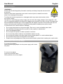
This device is a switching type power supply and can work with supply voltages in the range 100 - 240
VAC For worldwide usability four different AC adapters are enclosed: Euro type, UK type, US/Japan type
and Australia/New Zealand type. Use the appropriate AC adapter as shown in the picture and ensure it
is firmly secured in place and does not detach by pulling before installing into a power socket.
To reduce risk of fire, electric shocks or damage:
Do not open the product nor its power supply. There are no user serviceable parts inside.
Only qualified servicing personnel may carry out any repairs or maintenance.
Never use damaged cables.
Do not expose the product to water or places of moisture.
Do not use this product outdoors it is intended for indoor use only.
Do not place the product near direct heat sources. Always place it in a well-ventilated place.
Do not place heavy items on the product or the cables.
Please ensure any adapters are firmly secured and locked in place before inserting into a wall socket
Instructions for Use of Power Supply
To connect the adapter
Slide the desired plug adapter into the power supply until it locks
into place.
To remove the adapter
Press the push button latch.
While pressed, remove the adapter.

User Manual English
Introduction
Thank you for purchasing the SDVoE Controller. This product has been designed to provide trouble free,
reliable operation. It benefits from both a LINDY 2-year warranty and free lifetime technical support. To
ensure correct use, please read this manual carefully and retain it for future reference.
SDVoE is a globally recognised standard for high quality distribution of AV content with other features,
including control, matrix, video wall and multi view over longer distances via 10G Network with no
compressions and latency.
This Controller can be used to manage the Lindy SDVoE Transceiver 38365 that features HDMI, USB, IR,
RS-232 and Audio signals to distribute all the signals through a 10G managed network switch and to set
up many configurations and layouts. It supports dual network ports, one for network control and one for
multicast video distribution.
It provides control via Web GUI, TCP, RS-232, IR & GPIO.
SDVoE Alliance® is a registered trademark and SDVoE™ and SDVoE API™ are trademarks of the SDVoE
Alliance.
Package Contents
SDVoE Controller
IR Emitter Cable, 1.5m
IR Receiver Cable, 1.5m
2 x Mounting Ears & 4 x Screws
2 x 3-Pin Terminal Block
6-Pin Terminal Block
12VDC 1A Multi-country Power Supply (UK, EU, US & AUS), Screw Type DC Jack: 5.5/2.1mm
Lindy Manual
Features
Supports video, audio, RS-232, IR, KVM control and management of the distributed system
Maximum point-to-point Distance: 100m (328.08ft)
PoE (Power over Ethernet) support on Video LAN port
Built-in Web GUI control interface, supporting Drag & Drop operations and image preview
Dual network ports to isolate Controls and Multicast networks
Support LAN/RS-232 port control and third-party central control (API commands available on request)
Support IR Control (20 – 60KHz) on IR IN 3.5mm port (12V)
4 channel GPIO control ports (5V/12V optional level)
HTTPS, SSH, SFTP security compatible
Screw Type DC Jack for a secure power connection
Specification
Transmission distance: 100m
Network Video Bandwidth: 1G
PoE Standard: 802.3at
Operating Temperature: 0°C - 40°C (32°F - 104°F)
Storage Temperature: -20°C - 60°C (-4°F - 140°F)
Relative Humidity: 20 - 90% RH (Non-condensing)
Metal Housing
Colour: Black
Power Requirements: AC100-240V 50/60Hz
Power Consumption: 8.4W

User Manual English
Installation
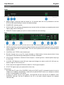
Front
1. RESET Button: Press and hold this button for 10 seconds when the unit is powered-on until the
STATUS LED starts flashing to restore the default settings.
2. POWER LED: Indicates power.
3. STATUS LED: This will flash yellow/green every second until the unit boots up completely and control
LAN is ready, then it will stay on.
4. UPDATE: Firmware update port (do not connect it while the unit is working).
Rear
1. DC 12V: Connect the 12VDC 1A PSU to an AC wall outlet and securely connector to the unit.
2. VIDEO LAN (PoE): Connect to the same Network Switch where all SDVoE Transceivers are connected
using a single RJ-45 Cat.6 or above cable. The unit can be powered via PoE if the connected Switch
has this feature.
3. CONTROL LAN: TCP/IP control network port.
4. RS-232: Connect one or two PC, Serial Controller or Serial device via two phoenix block 3-way
connection for the pass-through transmission of RS-232 commands.
5. 6-Pin Phoenix Connector: 4 channel I/O level outputs, 1 channel ground, 1 channel power output (up
to 12V 0.5A)
6. IO LEVEL: DIP Switch to control I/O level output and Voltage out; switch to left for 5V I/O level out,
switch to right for 12V I/O level out.
7. IR IN: Connect the supplied IR Receiver cable for 12V IR signal reception.
8. IR OUT: IR signal output port (reserved for future use).
Please Note:
- As default the IP mode of the CONTROL LAN port is DHCP, the PC connected needs to be set to
“Obtain an IP address automatically” mode and an optional DHCP server (for example a network
router) is recommended in the system.
- If there is no DHCP server in the system, 192.168.0.225 will be used as the IP address of the
CONTROL LAN port. Set the IP address of the PC in the same network segment (for example
192.168.0.88).

User Manual English
Operation
Web GUI
This Controller can be managed via the built-in Web GUI.
Please follow the below steps:
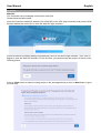
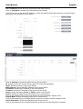
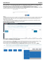
Input the Controller’s default IP address (192.168.0.225) or the URL (http://controller.local) into the Web
browser address bar on the PC to enter the Web GUI login interface:
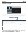
Select the default username (admin) and password (1234) on the above login interface. Then, click on
Log In to enter the Web GUI interface. For the first time, you need to setup the project, as shown in the
following picture:
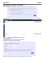
Click on Close button to load an existing project in the web page directly or click on Next button to go to
the next step.

User Manual English
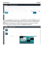
On this interface, you need to set the IP mode of Video LAN.
Mode 1: Automatically managed by Controller Box
Click on Next button and wait for the completion to enter the interface as shown below:
Select Automatically add Encoders and Decoders to project and click on Scan button to enter the
Project page. All the connected devices will be listed in the Current Devices list.
Then click on Stop Scan & Auto Assign to stop the search.
Mode 2: DHCP mode
Please follow the same steps shown in Mode 1 operation.
Mode 3: Static IP mode by manual settings
Manually set the IP Address, Subnet Mask and Gateway of the Video LAN port.

User Manual English
Then please follow the same steps shown in Mode 1 operation.
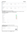
Preview Page
On this page is possible to see the preview of the Encoder/Decoder by clicking on the dropdown lists.
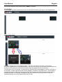
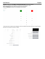
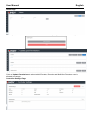
Matrix Control Page
Encoders: Display all the connected Encoders. The text in the figure is the name of the device.
Decoders: Display all the connected Decoders. The text on the first line is the name of the Decoder and
the text on the second line refers to the Encoder where the signal resource comes from.
If an Encoder shows “No Signal”, it means that the Encoder cannot be dragged. If there is an image on
an Encoder, it means that the Encoder can be dragged. As shown in the figure above, if an Encoder is
dragged to the place where the red arrow points to, all Decoders will share the same signal resource
from this Encoder; if an Encoder is dragged to the place where the blue arrow points to, only the
indicated Decoder can receive signals from this Encoder.

User Manual English
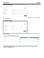
Project Page
Current Devices: Devices that have been added to the current project.
Unassigned Devices: Devices not added to the current project.
Click on Display ID to display the ID or PATTERN of the Decoders.
Click on Save Project to save the project file (config_file.json) in order to use the saved project next time
without scanning devices again.
Click on Load Project to load the existing project directly.
Click on Clear Project to clear the current project, then is needed to setup the project again.
Click on Scan Once to search devices that do not appear in the current project.
Click on Start Scan & Auto Assign to search new devices automatically and add them to the current
project.
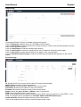
Encoders Page
Click on Refresh to refresh the data of the current Encoders.
ID: Shows the ID of the current device* (Note: ID cannot be duplicated).
Name: Shows the name of the current device.
MAC Address: Shows the MAC Address of the current device.
IP Address: Shows the IP Address of the current device.
Firmware: Shows the Firmware version of the current device.
Status: Shows the status (Online or Offline) of the current device.
EDID: Shows the EDID of the current device.
Click on the drop-down list to set the current Encoder’s EDID; select a resolution or User EDID 1 / User
EDID 2 to assign a bin file uploaded from Firmware Update and EDID Upload page.
Audio Selection: Shows the audio selection of the current device.
Click on the drop-down list to set the current Encoder’s audio output.

User Manual English
CEC Command: Shows the CEC Command of the current device.
Click on Command to set the CEC command for the Encoder.
*Click on the icon on the left of ID numbers to check the detailed information about the current Encoder
and setup it as required, as shown below:
Decoders Page
Click on Refresh to refresh the data of the current Decoders.
ID: Shows the ID of the current device* (Note: ID cannot be duplicated).
Name: Shows the name of the current device.
MAC Address: Shows the MAC Address of the current device.
IP Address: Shows the IP Address of the current device.
Firmware: Shows the Firmware version of the current device.
Status: Shows the status (Online or Offline) of the current device.
Source: Shows the signal source (Encoder) of the current device.
Click on the drop-down list of Source to select the current Decoder’s signal source.
Display Mode: Shows the display mode of the current device.
Click on the drop-down list of Display Mode to select the current Decoder’s display mode.
Scaler Resolution: Shows the resolution of the current device.
Click on the drop-down list of Scaler Resolution to select the current Decoder’s resolution.

User Manual English
Function: Shows the mode (Matrix / Video Wall / Multiview) of the current device.
Click on the drop-down list of Function to select the current Decoder’s mode.
CEC Command: Shows the CEC Command of the current device.
Click on Command to set the CEC command for the Decoder.
*Click on the icon on the left of ID numbers to check the detailed information about the current Decoder
and setup it as required, as shown in below:

User Manual English
Locked Signal Routing Page
On this page is possible to independently route the video and audio signals between Encoder & Decoder
devices. The IR/Serial/USB signals can be set up as required, by default are setted as N/A (Not Active),
select Follow to activate the required signals. Please click on Locked Routing Help for details.
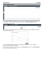
Video Wall Management Page
On this page is possible to create and configure video wall applications. Click on Create, the following
pop-up window will be shown:
Set the Video Wall ID, Name, Horizontal and Vertical panel numbers. Then click on Create.
Note: Up to 9 video walls can be created.
Select the video wall that you want to configure on the Video Wall List, then click on Assign Decoder
to enter the Decoder assignment page.

User Manual English
Click on each screen to select the corresponding Decoder device, then click on Apply.
Note: A Decoder can only be assigned to one video wall.
Click on Class Configuration to enter the class configuration page, then click each screen to select the
corresponding Class as required (the same class name will form a video wall, you can create a regular
or irregular video wall). Then click on Apply.
Note: Up to seven configurations can be set up for different application scenarios.
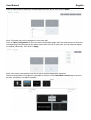
After the configuration is completed, is possible to check it on the Video Wall Control page to see the
preview, as shown in the below example:

User Manual English
Here is possible to select different video walls and configurations saved in advance by clicking on the
drop-down boxes under Video Wall Selection and Configuration Selection. It’s also possible to drag
the Encoders directly on the top of the page to the video wall to change the signal sources.
To delete a video wall, just select the video wall on the Video Wall List, then click on Remove. A prompt
window will pop up and it can be deleted after clicking on Yes.
Notes:
- Each Decoder can be set into a part of a video wall array. Each system can contain multiple video walls
with different sizes. Each video wall can be assigned to different screens and different layouts with a
range from 1x2 up to 9x9.
- The controller creates and manages the video wall configurations and provides a simplified control
interface and API commands to third party control system.
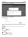
Multiview Management Page
On this page is possible to create and configure Multiview and PiP options as required. Please follow the
below steps under Multiview Configuration:
Click the drop-down list of Decoders to select the Decoder device as shown in the above figure. Then
click to select the desired Layout Type, which will be displayed in the lower right corner.
Drag Encoders from the Encoder List to the Multiview Layout respectively, then click on Apply.

User Manual English
After the configuration is completed, is possible to check it on the Multiview Control page to see the
preview, as shown in the below example:
Here is possible to select different Decoders and configurations saved in advance by clicking the drop-
down box under Receiver Selection and Configuration Selection.
To delete one Multiview configuration click on Reset, to delete all Multiview configurations click on Reset
All; a prompt window will pop up and it can be deleted after clicking on Yes.
To Create PiP Layout click on Add button and select a MultiViwe PIP ID number, change the name if
required. Then the new layout should be visible under the Layout List on the left, select a Layout Type
and chose the windows for the Encoder Assignment. Click on Apply to confirm.

User Manual English
Click on PiP Configuration to manage the PiP Layout selected. Click on Add to create a MultiView
Preset, select an ID and change the name if required. Drag Encoders from the Encoder List to the
Layout windows respectively and click on Apply. Select the Decoders to show the layout and click on
Apply.
Please Note: for PIP configurations the highest resolution possible for the Encoders can be 4K30.
Select the Multiview/PIP Configuration created from the Multiview Control page.

User Manual English
Users Page
Here is possible to add new user accounts. Click on More to update permissions or delete any user.
Click on Update Permissions to select which Encoder, Decoder and MultiView Presets a user is
allowed to manage.
Controller Settings Page

User Manual English
General Settings: Shows the basic settings of the Controller.
Domain Name: Shows the name of the Controller.
Control Network: Shows the network port configuration of the Controller connected to the Switch.
Is possible to set up the Options as follows or Reset Controller.
General Settings Options
Set Off/On control and access options of the Controller.
Domain Name Options
Rename the Controller unit, click on Update to confirm.

User Manual English
Control Network Options
Set Off/On DCHP of the Controller Network port, IP Address, Subnet and Gateway can be also changed
if DHCP is disabled.
Video Network Options
Set Off/On DCHP of the Controller Video port, IP Address, Subnet and Gateway can be also changed if
DHCP is disabled.
Firmware Update and EDID Upload Page
Here is possible to upload separately the firmware of any Encoder/Decoder and then click on the
corresponding Update button on the right or update all the firmware simultaneously by clicking the
corresponding Update All button.

User Manual English
Click on Upload User EDID 1 or Upload User EDID 2 buttons to upload a bin file, then it can be
assigned to any encoder as shown in Encoder page.
Click on Upload User EDID 1 or Upload User EDID 2 buttons to upload a bin file, then it can be
assigned to any encoder as shown in Encoder page.
Password Update Page
Here is possible to change the password. Please note that after changing, it will skip to the Web browser
home page or the Web GUI login interface automatically. Then log in the Web GUI again with the new
password.
Log Out Page
Click on Log Out on the left, the Web GUI will exit and skip to the login interface automatically.
Infrared Pinout

User Manual English
Network Switch
The network Switch used to set up the system must support the below features:
• Layer 3/managed
• Bandwidth 10 Gigabit
• Support IGMP version 2, snooping enabled
• Filter/Drop unregistered multicast traffic
• Disable unregistered multicast flooding
• Enable fast leave support
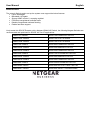
Lindy tested this SDVOE Extender with a Netgear XSM4316S Switch, the following Netgear Switches are
recommended and optimized for SDVOE AV over IP applications:
XSM4216F-100NAS M4250-16XF MANAGED SWITCH
XSM4316PA-100NES M4300-16X POE+ APS299W
XSM4316PB-100NES M4300-16X POE+ APS600W
XSM4316S-100NES M4300-8X8F MANAGED SWITCH
XSM4324CS-100NES M4300-24X MANAGED SWITCH
XSM4324FS-100NES M4300-24XF MANAGED SWITCH
XSM4324S-100NES M4300-12X12F MANAGED SWITCH
XSM4348CS-100NES
M4300-48X MANAGED SWITCH
XSM4348FS-100NES
M4300-48XF MANAGED SWITCH
XSM4348S-100NES
M4300-24X24F MANAGED SWITCH
XSM4396K0-10000S
M4300-96X NO PORT CARD / NO PSU
XSM4396K1-100NES
M4300-96X 48XSFP+ APS600W BNDL
Seite wird geladen ...
Seite wird geladen ...
Seite wird geladen ...
-
 1
1
-
 2
2
-
 3
3
-
 4
4
-
 5
5
-
 6
6
-
 7
7
-
 8
8
-
 9
9
-
 10
10
-
 11
11
-
 12
12
-
 13
13
-
 14
14
-
 15
15
-
 16
16
-
 17
17
-
 18
18
-
 19
19
-
 20
20
-
 21
21
-
 22
22
-
 23
23


in anderen Sprachen
- English: Lindy SDVoE Controller User manual
- italiano: Lindy SDVoE Controller Manuale utente
- eesti: Lindy SDVoE Controller Kasutusjuhend
Verwandte Artikel
-
Lindy 4x4 HDMI 4K60 Matrix Benutzerhandbuch
-
Lindy 38238 Benutzerhandbuch
-
-
-
Lindy 73412 Benutzerhandbuch
-
-
-
Lindy 73410 Benutzerhandbuch
-
Andere Dokumente
-
VONMAEHLEN AIR BEATS Bedienungsanleitung
-
Axis Communications M7001 Benutzerhandbuch
-
Yamaha v4 Benutzerhandbuch
-
Axis Communications M7001 Benutzerhandbuch
-
Axis Q7404 Video Encoder Installationsanleitung
-
-
-
Yamaha V3 Bedienungsanleitung
-