
INSTALLATION AND OPERATING INSTRUCTIONS
INSTRUCTIONS D’INSTALLATION ET D’UTILISATION
MONTAGE- UND BEDIENUNGSANLEITUNG
ISTRUZIONI PER L'INSTALLAZIONE E L'USO
INSTRUCCIONES DE INSTALACIÓN Y DE FUNCIONAMIENTO
INSTRUÇÕES DE INSTALAÇÃO E UTILIZAÇÃO
Air Curtain
Rideau d’air
Luftschleier
Barriera d’aria
Cortina de aire
Cortina de ar
Model No. FY-3009U1
N° de modèle FY-3012U1
Modellnr. FY-3015U1
Modello n.
Nº de modelo
Modelo N. º
Thank you for purchasing this Panasonic product.
Merci d’avoir acheté cet appareil Panasonic.
Vielen Dank für den Kauf dieses Produkts aus dem Hause Panasonic.
Grazie per aver acquistato questo prodotto Panasonic.
Gracias por comprar este product Panasonic.
Obrigado por comprar este produto Panasonic.

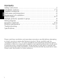
Contents
Safety instructions .................................................................................2
Installation cautions .......................................................................... 2
~
3
Supplied accessories ..............................................................................4
Parts name and dimensions ...................................................................4
Requirement of installation ....................................................................5
How to install ................................................................................... 6
~
7
Multiple products operate in group ........................................................8
Wiring diagram ......................................................................................8
Operation methods ................................................................. 8
~
9
Routine maintenance .................................................... 10
~
11
Trouble shooting..................................................................................12
Specifications .......................................................................................13
Please read these installation and operating instructions carefully before attempting
to install, operate or service the Panasonic product. Please carefully read the
“Installation cautions” (P.2
~
3) of this installation and operating instructions before
installation. Failure to comply with installation and operating instructions could result
in personal injury or property damage. Please explain to users how to operate and
maintain the product after installation, and this booklet should be presented to users.
Please retain this booklet for future reference.
1

If the supply cord is damaged, it must be replaced by the manufacturer,
its service agent or similarly qualified persons in order to avoid a hazard.
This appliance can be used by children aged from 8 years and above and
persons with reduced physical, sensory or mental capabilities or lack of
experience and knowledge if they have been given supervision or
instruction concerning use of the appliance in a safe way and understand
the hazards involves.
Children shall not play with the appliance. Cleaning and user maintenance
shall not be made by children without supervision.
Make sure to disconnect the power supply before cleaning product.
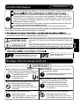
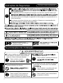
The following explanations must always be observed in order to prevent harm to
users or other people and prevent damage to property.
The following displays are classified and explained to what extent harm or damage
occurs when the display details are ignored and the unit in question is wrongly used.
WARNING
This indication means: Must be treated seriously that
this may result in death or serious injury.
CAUTION
This indication means: Must be treated seriously that
this may result in injury or property damage.
The types of details to be observed are classified and explained in the following
illustrated displays. (Below are the series of illustrated displays)
This symbol indicates the
“COMPULSORY” item that must
be followed without failure.
This symbol indicates the item
“PROHIBITED” to do.
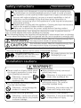
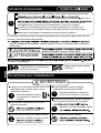
Safety instructions
Please observe strictly
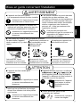
Installation cautions
Please install an all-pole switch which
the contact separation is more than
3mm (Double pole switch).
Otherwise, it may cause
a short circuit, thus
resulting a fire.
Do not operate the product other
than the rated voltage.
Otherwise, it may damage the
product or cause fire.
The product must be grounded.
Otherwise, it may cause electric
shock when there is any trouble
or electric leakage.
Wiring should be firmly connected
without any loose.
Otherwise, it may cause a short
circuit, thus resulting a fire.
Installation should be done by
authorized person. The product
should be installed firmly.
Otherwise, the product may fall
down and it may cause injury.
Do not reconstruct this product.
Otherwise, it may cause damage
to the product or injury.
WARNING
2

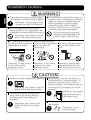
Installation cautions
Product must be installed by 2 persons.
Otherwise, the product may fall
down and it may cause injury.
The special-purpose or dedicated
parts, such as mounting fixtures,
must be used if such parts are
provided.
Otherwise, the product may
fall down and it may cause
injury.
The product must be mounted on a
building which is strong enough. To
ensure it can bear over 5 times of
product weight. The building must be
reinforced if its strength can not be
ensured.
Otherwise, the product
may fall down and it
may cause injury.
Please wear the gloves when installing
the product.
Otherwise, it may
cause damage.
CAUTION
The product must be installed tightly.
Components must be installed tightly.
Otherwise, it may injury person
caused by product’s falling off.
Do not install the product as the
method which is not approved in the
installation and operating instructions.
Otherwise, the product any fall
down and it may cause injury.
It’s prohibited to install the product in
locations such as machinery, chemical
plants or research facilities where it
will be exposed to noxious gases
containing acids, alkali, organic
solvents, paint fumes, etc., to gases
contaning corrosive ingredients.
It could cause gas poisoning,
corrosion and degradation of
product that results in a fire.
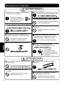
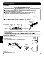
WARNING
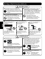
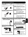
It’s prohibited to install in the following locations.
Do not install the product
where there is steam.
Location with combustible
gas or emission of
exhaust gas.
Do not install the product
out of the window and
wall.
Indoor Outdoor
Otherwise, it may cause
a short circuit, thus
resulting in a fire.
Otherwise, it may cause
a short circuit, thus
resulting in a fire.
Otherwise, the product
may get wet in the rain
and cause a short circuit.
3

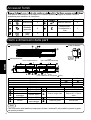
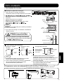
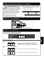
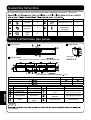
The following attachments are enclosed in the packing box of product. Be sure to
check if they are complete after unpacking, and if anything is missed, contact our
After-Sales Service Centre or the dealer.
No. Drawing Name Quantity No. Drawing Name Quantity
Washer 6 Bolt M8×60L 6
Spring
washer
6
Installation and
operating
instructions
1
Nut
(M8)
6
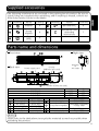
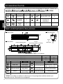
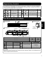
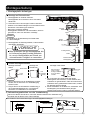
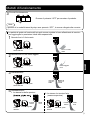
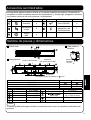
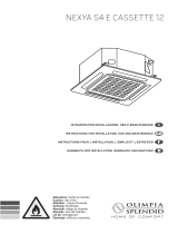
Front view
Back view
Power supply cord
6 holes
(M8 bolts are used)
8 holes
( 8mm wooden screws are used)
Right view
Direction
of
Air outlet
Model No. A B
FY-3009U1 900 50
FY-3012U1 1200 200
FY-3015U1 1500 350
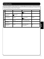
No. Part name Classification No. Part name Classification
Front panel Resin ABS Motor support Steel SGCC
Air outlet Resin ABS
Cross-flow impeller
Steel plate + ResinAS
+ Glass fiber
Mounting plate Steel SGCC
Back panel Steel SGCC Push–button switch Assembly part
Motor Assembly part Guide plate Resin ABS
Notice
Please refer to the table above to recycle the materials as much as possible when
discarding this product.
Parts name and dimensions
Supplied accessories
4

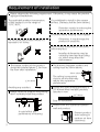
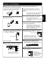
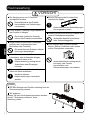
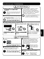
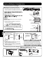
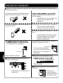
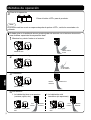
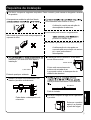
Requirement of installation
The applicable ambient temperature
of this product is in the range of
-10°C
~
40°C.
Do not install the product where it is
exposed to oil fumes.
It’s prohibited to install in the uneven
surface. (Flatness shall be 3mm below.)
Distortion results in reducing the
separation performance.
Locations where freezing could happen.
Otherwise, it may damage the
product or cause fire.
Do not install the product in the place
with many dust.
Impeller deformation may be
caused by sand and dust piling
up, which may affect the
performance.
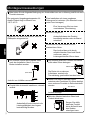
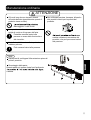
Please observe the following requirement. Otherwise, it may cause the product
aging and breakdown.
The lowest surface of this product
should be installed above 2.3m from
the floor after installation.
Avoiding any accident.
Please install the product horizontally,
don’t vertically install the product.
It could affect the
performance of bearing.
The distance between product and
ceiling must be 50mm above.
The ceiling is excessively
close to air inlet that may
reduce the separation
performance.
Ensure the space among products is
20
~
40mm when multiple products
operate in row.
20
~
40mm
Easy for installation.
Please block the clearance between
wall and product.
Prevent product
from sucking in
outdoor air from
clearances.
2.3m above
50mm above
5

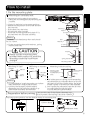
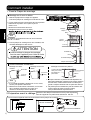
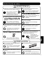
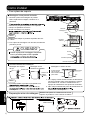
How to install
1. Fix the mounting plate
Mounting on concrete wall.
1. Remove mounting plate from product.
Taking the mounting plate by removing the
3 screws.
2. Firmly fix the bolts in the proper position.
· Determine the position on the wall and drill
into the wall.
· Fit the bolts into the holes.
· Fill the holes with concrete.
· Install the mounting plate and check if it’s
secured when the concrete solidifies.
Notice
Distance of bolt head away from wall should
be 13
~
15mm.
3. Fix the mounting plate with washers, spring
washers and nuts.
2.Preparation before wiring
Carry out this step if the distance between top
(
face of product and ceiling is less than 150mm.
)
Pre-hang up the product into the bottom holes of mounting plate.
150mm above
Bottom holes
Mounting
Plate
Screw
Concrete
Bolt
M8×60L
13-15mm
About 70mm
Diameter: 40-50mm
Washer
Wall
Nut
Spring washer
Mounting plate
Please use the mounting plate
provided with product to avoid the
dropping caused by insufficient
strength.
CAUTION
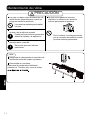
Other installation methods
M8 bolt
15mm
below
100mm above
Partition plate
(not supply) is
installed at four
sides.
Ceiling
350mm above
Wooden
screw
( 8×60L)
Mounting on steel
hanger
Notice
1. It’s prohibited to install the product on hollow
wall, otherwise it may produce noises.
2. Conduct the necessary reinforcement,
depending on the particular condition to
avoid noise resonance and vibration.
1. The inside space of ceiling should exceeding
the dimensions as indicated above to ensure
the space of air inlet, please select the larger
model if space of air inlet can’t be reserved.
2. Don’t place the substances near the air inlet
or outlet grille (include the grille).
It could affect the performance.
Mounting on wooden
frame
Mounting inside the ceiling
6

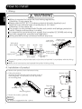
How to install
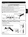
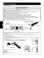
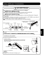
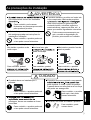
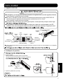
3. Wiring
Wiring is required to follow the local wiring regulations.
Otherwise, it may cause fire.
Please select 60227 IEC 53 ordinary polyvinyl chloride sheathed cord.
Nominal cross-sectional area of conductors is 3×1.0mm
2
.
Otherwise, it may cause fire.
The product is not provided with Double pole switch and leakage protection
switch. Please purchase them in market.
It is required to use terminal (not supply) that complies IEC 60998 and wiring
box (not supply) that complies local regulation.
Wiring should be firmly connected without any loose.
WARNING
Wiring box
(not supply)
Neutral
(N)
Live
(L)
Brown
(L)
Blue
(N)
Power cord
of the product
Green/Yellow
(Earth)
Terminal block
(not supply)
Earth wire
Power
supply cord
Lead wire
from source
Air curtain
Power cord
of the product
Connect the power cord (included earth) of product to lead wire in accordance with the wiring
diagram.
Make sure all connections are fastened firmly after finishing wiring.
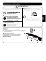
4. Installation of product
1. Remove the product from the bottom holes.
2. Fixing the product.
Align the groove of back panel with both sides of
mounting plate. Fit the hooks into the top holes
of mounting plate.
Groove
Mounting plate
Back panel
3. Fasten the screws. (3 places)
Notice
The torque is suggested to be 1.2N·m.
Bottom holes
Top holes
7

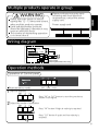
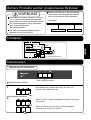
Multiple products operate in group
Please purchase necessary parts
following with local electrical
requirements, except the power
supply cord.
Power supply cord
Please select the switch of whose
capacity has 1.2
~
1.5 times total current,
when multiple products operate.
Earth leakage breaker protector
should be equipped, otherwise it may
cause an electrical shock.
The number of interlocking operation
is not more than 6.
WARNING
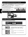
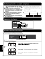
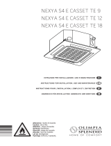
Wiring diagram
Motor
Red
Orange
Black Black
Green/Yellow
Blue
Brown
Double Pole Switch
Customer Provide
(Contact Point Separate Distance Over 3mm)
Switch
White
White(H)
Yellow(L) Yellow
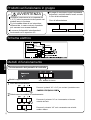
Operation of Control panel
OFF LOW HIGH
Operation methods
Representative model
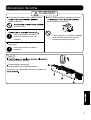
1
Start to operate
2
Select the mode of operation
Press “HI” or “LO” button to start the product as
shown in left figure.
Press “HI” button if high air velocity is required.
Press “LO” button if quiet and low velocity is
required.
Capacitor
8

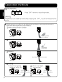
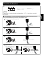
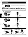
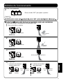
Guide vane in air outlet can be adjusted according to service environment to
reach the ideal separation performance.
1
While strong wind in outdoor
Air outlet
Guide vane
Strong wind
in outdoor
2
While light wind in outdoor
Air outlet
Guide vane
Light wind
in outdoor
3
Heating
Air outlet
Guide vane
Hot indoor Cold outdoor
4
Cooling
1. Room has opening
(window, grille, etc.)
Air outlet
Guide vane
Cold
indoor
Hot
outdoor
Air outlet
Guide vane
Cold
indoor
Hot
outdoor
Operation methods
3
Stop operating
Notice
The product is in stand-by mode after pressing the “OFF”, it’s still connected to the
power.
Press “OFF” button to stop the product.
2. Room is air tight
(no opening)
9

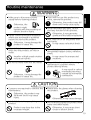
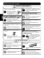
Routine maintenance
Make sure to disconnect power
supply before cleaning product.
Otherwise, the
product might
operate with the possibility of
electric shock or injury.
Please contact entrusted distributor
where you purchased or qualified
persons to service the product.
Otherwise, it may damage the
product or cause fire.
It’s prohibited to insert fingers or
sticks into the product, air inlet or
outlet.
Impeller at high speed rotation
may cause injuries.
Do not let water flow into the motor.
Otherwise, it may damage the
product or cause fire.
If you will not use this product any
more, remove the product.
Otherwise, the product may fall
down and it may cause injury.
Once flammable gas leaks, do not
start any function of this product.
Otherwise, it may generate
sparkle and this leads to explosion.
Don’t turn on or off the power with
wet hands.
It may cause a electrical shock.
Immediately stop to wait for repair if
abnormities happen (noise, vibration,
smell).
It may cause the unexpected
accidents.
It’s prohibited to place the burning
appliances in a position where
product directly blows.
It may result in carbon
monoxide poisoning
caused by incomplete
combustion.
WARNING
2 persons are required to conduct the
maintenance.
Otherwise, the product may
fall down and it may cause
injury.
It’s forbidden to hang anything on the
product.
Product may drop due to the
increased weight.
Please wear the gloves when cleaning
the product.
Otherwise, it may cause damage.
Do not directly spray this product with
water and other liquids.
Otherwise, it may cause short
circuit or electric shock.
CAUTION
10

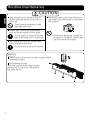
Routine maintenance
Eyes should not be faced to the air
outlet (specially when the product
stars up).
The blowing substance could
damage your eyes.
Please don’t place the substances
near to the air outlet or inlet grille.
It may result in personal injuries
due to blowing out or sucking in.
The strong air from air curtain may
cause the sand and dust.
It may result in personal injuries.
Never use petrol, benzene, thinner or
any other such chemicals for cleaning
the product.
Metallic brush
Otherwise, dropping caused by
corrosion of product, which may
result in personal injuries.
CAUTION
Notice
Make sure to disconnect power supply before
cleaning product.
Disassembly of part
This part can be easily taken out by
removal of 7 screws as indicated in
the right figure.
11

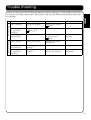
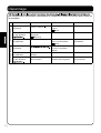
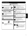
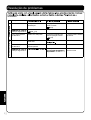
Trouble shooting
Check according to the following table and take measures. If the product still does
not work normally, disconnect the power and contact After-Sale Service Centre or
the dealer.
Condition 1st Possible reason 2nd Possible reason 3rd Possible reason
Primary Period
Can’t operate. Check the voltage. Wiring is not correct.
( P7)
With large noise
or significant
vibration.
Installed not properly.
( P6 P7)
Poor separation
performance.
Not suitable model. Guide vane is not in
proper position.
( P9)
Product is installed
vertically.
During operation
Can’t operate. Wiring is not fixed. Double pole switch
became off.
Poor separation
performance.
Air inlet grille is
blocked.
With large noise
or significant
vibration.
Dust piles up in
impeller.
Any other substances
fell into the product.
Motor runs
abnormally.
12

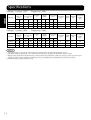
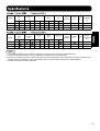
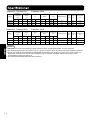
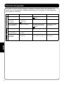
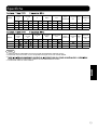
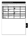
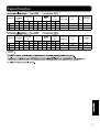
Voltage: 1 phase 220V Frequency: 50Hz
Model
Outlet
Velocity
m/s
Power
Consumption
W
Current
A
Noise
dB(A)
Air Volume
m³/h
Insulation
Class
Length
mm
Weight
kg
Installation
height
(m)
High Low High Low High Low High Low High Low
FY-3009U1 10.5 8.5 76 70 0.35 0.32 48.5 45 1100 920 B 900 12 3.0
FY-3012U1 9.5 8 94 85 0.43 0.4 48.5 44.5 1400 1270 B 1200 14.5 3.0
FY-3015U1 10.5 9.5 131 110 0.59 0.5 51.5 48 2000 1800 B 1500 18 3.0
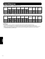
Voltage: 1 phase 240V Frequency: 50Hz
Model
Outlet
Velocity
m/s
Power
Consumption
W
Current
A
Noise
dB(A)
Air Volume
m³/h
Insulation
Class
Length
mm
Weight
kg
Installation
height
(m)
High Low High Low High Low High Low High Low
FY-3009U1 10.5 9 86 80 0.37 0.35 50.5 47.5 1150 960 B 900 12 3.0
FY-3012U1 10 8.5 107 95 0.46 0.43 50.5 47 1500 1320 B 1200 14.5 3.0
FY-3015U1 11 10 145 115 0.6 0.5 53.5 50.5 2100 1850 B 1500 18 3.0
Notice
1. The parameters as shown in above table are measured at ambient temperature of 20°C.
2. The noise value is measured 1.5m away from the product at angle of 45° below the air outlet.
3. Because the above-mentioned velocity is measured in test laboratory where it’s empty, without air flow and
obstacle, after actual installation the velocity may vary depending on different service environment.
4. Outlet velocity is the maximum value.
Specifications
13

Table des matières
Consignes de sécurité ............................................................................................. 2
Mises en garde concernant l'installation .............................................................. 2~3
Accessoires fournis ................................................................................................. 4
Nom et dimensions des pièces................................................................................ 4
Exigence d'installation ............................................................................................. 5
Comment installer................................................................................................ 6~7
Plusieurs appareils fonctionnent en groupe ............................................................ 8
Schéma de câblage ................................................................................................. 8
Procédés d'utilisation ............................................................................. 8~9
Maintenance de routine .............................................................. 10~11
Dépannage ............................................................................................................ 12
........................................................................................................ 13
Veuillez lire attentivement ces instructions d'installation et d'utilisation avant d'essayer d'installer,
d'utiliser ou de réparer le produit Panasonic. Veuillez lire attentivement les « Mises en garde
concernant l’installation » (P.2~3) de ces instructions d’installation et d’utilisation avant de
procéder à l’installation. Le non-respect des instructions d'installation et d'utilisation peut
entraîner des dommages corporels ou matériels. Veuillez expliquer aux utilisateurs comment
utiliser et entretenir l’appareil après l'installation, et cette brochure devrait être présentée aux
utilisateurs.
Veuillez conserver cette brochure en guise de référence ultérieure.
1

Les ex
utilisateurs ou à d'autres personnes et d’éviter les dégâts matériels.
question est mal utilisé.
AVERTISSEMENT
avec rigueur le fait que cela pourrait entraîner la
mort ou des blessures graves.
ATTENTION
avec rigueur le fait que cela pourrait entraîner
des blessures graves ou des dégâts matériels.
Ce symbole indique l'élément
« OBLIGATOIRE » qui doit être suivi
sans défaillance.
Ce symbole indique l'élément
« INTERDIT » de suivre.
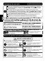
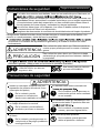
Si le cordon d'alimentation est endommagé, il doit être remplacé par le fabricant,
éviter tout danger.
Cet appareil peut être utilisé par des enfants âgés de 8 ans et plus et des
personnes ayant des capacités physiques, sensorielles ou mentales réduites ou un
ou reçu des instructions concernant l'utilisation de l'appareil de manière sécuritaire
et qui comprennent les dangers impliqués.
Les enfants ne doivent pas jouer avec l'appareil. Le nettoyage et l’entretien de
l'utilisateur ne doivent pas être faits par des enfants sans surveillance.
Assurez-vous de débrancher l'alimentation avant de nettoyer l’appareil.
Consignes de sécurité
Veuillez respecter strictement
Mises en garde concernant l'installation
Veuillez installer un interrupteur multipolaire
dont la séparation de contact est
supérieure à 3 mm (Interrupteur bipolaire).
Autrement dit, il peut
provoquer un court-circuit,
entraînant ainsi un incendie.
N’utilisez pas l’appareil sous une tension
autre que la tension nominale.
Autrement dit, cela pourrait
endommager l’appareil ou provoquer
un incendie.
L’appareil doit être mis en terre.
Autrement dit, il peut provoquer un
choc électrique en cas de problème
ou de fuite électrique.
Le câblage doit être bien branché sans
aucun relâchement.
Autrement dit, il peut provoquer un
court-circuit, entraînant ainsi un
incendie.
L'installation doit être effectuée par une
personne autorisée. L’appareil doit être
installé solidement.
Autrement dit, l’appareil peut tomber
et causer éventuellement des
blessures.
Ne pas reconstruire cet appareil.
Autrement dit, cela pourrait
endommager l’appareil ou causer
des blessures.
AVERTISSEMENT
2

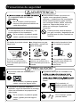
Mises en garde concernant l'installation
L’appareil doit être installé par 2
personnes.
Autrement dit, l’appareil peut tomber
et causer éventuellement des
blessures.
Les pièces à usage spécial ou dédiés,
telles que les accessoires de montage,
doivent être utilisées si de telles pièces
sont fournies.
Autrement dit, l’appareil peut tomber
et causer éventuellement des
blessures.
L’appareil doit être monté sur un bâtiment
peut supporter plus de 5 fois le poids de
l’appareil. Le bâtiment doit être renforcé si
sa solidité ne peut être assurée.
Autrement dit, l’appareil
peut tomber et causer
éventuellement des
blessures.
Veuillez porter des gants lors de
l'installation de l’appareil.
Autrement dit, cela peut
causer des dégâts.
ATTENTION
L’appareil doit être bien installé.
Les composants doivent être bien installés.
Autrement dit, l’appareil peut causer
des blessures en cas de chute.
N'installez pas l’appareil en utilisant une
méthode qui n'est pas approuvée dans les
instructions d'installation et d'utilisation.
Autrement dit, l’appareil peut tomber
et causer éventuellement des
blessures.
Il est interdit d'installer le produit dans des
endroits tels que des machines, des
installations chimiques ou des installations
de recherche où il sera exposé à des gaz
nocifs contenant des acides, des solvants
alcalins, organiques, des fumées de
peinture, etc., à des gaz contenant des
ingrédients corrosifs.
Cela pourrait provoquer une
intoxication au gaz, la corrosion et la
dégradation de l’appareil qui se
traduit par un incendie.
AVERTISSEMENT
Il est interdit de l'installer dans les endroits suivants.
Ne pas installer l’appareil
dans un endroit où il y a de la
vapeur.
Emplacement contenant du
gaz combustible ou des
émissions de gaz
d'échappement.
N'installez pas l’appareil loin
de la fenêtre et du mur.
A l’Intérieur A l’extérieur
Autrement dit, il peut
provoquer un court-circuit,
entraînant ainsi un incendie.
Autrement dit, il peut
provoquer un court-circuit,
entraînant ainsi un incendie.
Autrement dit, l’appareil peut
se mouiller sous la pluie et
provoquer un court-circuit.
3

Les pièces jointes suivantes se trouvent dans la boîte d'emballage de l’appareil. Prenez soin
veuillez contacter notre Centre de Service Après-Vente ou le revendeur.
Numéro Dessin Nom Quantité Numéro Dessin Nom Quantité
RONDELLE 6 Boulon M8 × 60L 6
Rondelle
élastique
6
Instructions de
montage et
d'utilisation
1
Écrou
(M8)
6
Vue de face
Vue arrière
Cordon d'alimentation
6 trous
(Les boulons M8 sont utilisés)
8 trous
(des vis en bois de 8 mm sont utilisées)
Vue de droite
Sens
de
Sortie d'air
Numéro de modèle A B
FY-3009U1
FY-3012U1 1200 200
FY-3015U1 1500 350
Numéro Nom de la pièce Numéro Nom de la pièce
Panneau avant Résine ABS Support moteur Acier SGCC
Sortie d'air Résine ABS
Turbine tangentielle
Plaque en acier + résines
AS + Fibre de verre
Plaque de montage Acier SGCC
Panneau arrière Acier SGCC
Interrupteur à
bouton-poussoir
Pièce d’assemblage
Moteur
Pièce
d’assemblage
Plaque de guidage Résine ABS
Avis
Veuillez vous référer au tableau ci-dessus pour le recyclage des matériaux autant que
possible lors de l’élimination de cet appareil.
Nom et dimensions des pièces
Accessoires fournis
4

Exigence d'installation
La température ambiante applicable de cet
appareil est de l'ordre de -10°C~40°C.
Ne pas installer l’appareil là où il sera exposé
à des vapeurs d'huile.
Il est interdit de l'installer sur une surface
inégale. (La planéité doit être de 3 mm en
dessous).
La distorsion entraîne une réduction
des performances de séparation.
Les endroits où le gel pourrait se produire.
Autrement dit, cela pourrait
endommager l’appareil ou provoquer
un incendie.
Ne pas installer l’appareil dans un endroit où
il y a beaucoup de poussière.
La déformation de la turbine peut
être causée par le déversement de
sable et de poussière, ce qui peut
affecter les performances.
Veuillez respecter les exigences suivantes. Autrement dit, cela peut provoquer un
vieillissement et une panne de l’appareil.
La surface la plus basse de cet appareil
devrait être installée au-dessus de 2,3 m
du sol après l'installation.
Éviter tout accident.
Veuillez installer l’appareil horizontalement,
ne pas installer verticalement l’appareil.
Cela pourrait affecter la
performance du roulement.
La distance entre l’appareil et le plafond
doit être supérieure à 50 mm.
Le plafond est excessivement
proche de l'entrée d'air qui peut
réduire les performances de séparation.
Assurez-vous que l'espace entre les
appareils est de 20~40 mm lorsque
plusieurs appareils fonctionnent en rangée.
20~40 mm
Facile à installer.
Veuillez bloquer le dégagement entre le
mur et l’appareil.
Empêcher à
l’appareil d'aspirer
l'air extérieur des
dégagements.
2,3 m au dessus
50 mm au dessus
5

Comment installer
1. Fixez la Plaque de montage
Montage sur le mur en béton.
1. Retirez la plaque de montage de l’appareil.
Prendre la plaque de montage en enlevant les 3 vis.
2. Fixez solidement les boulons dans la bonne position.
· Déterminer la position sur la paroi et percer
dans le mur.
· Montez les boulons dans les trous.
· Remplissez les trous avec du béton.
·
Avis
La distance de la tête de boulon loin du mur devrait
être de 13~15mm.
3. Fixer la plaque de montage avec des rondelles, des
rondelles élastiques et des écrous
2.Préparation avant le câblage
Effectuer cette étape si la distance entre la partie supérieure
(
face de l’appareil et le plafond est inférieure à 150 mm.
)
Pré-raccrochez l’appareil dans les trous inférieurs de la plaque de montage.
150 mm au dessus
Les trous inférieurs
Montage
Plaque
Vis
Béton
Boulon
M8×60L
13-15 mm
Environ 70 mm
RONDELLE
Mur
Écrou
Rondelle élastique
Plaque de montage
Autres méthodes d'installation
Boulon M8
15 mm en
dessous
100 mm au dessus
La plaque de sépa-
ration (non fournie)
est installée sur
quatre côtés.
Plafond
350 mm au dessus
En bois vis
( 8×60L)
Montage sur l'acier
crochet
Avis
1. Il est interdit d'installer l’appareil sur un mur creux,
sinon il peut produire des bruits.
2. Effectuez le renforcement nécessaire, en fonction
de la condition particulière pour éviter une
résonance acoustique et des vibrations.
1. L'espace intérieur du plafond devrait dépasser les
dimensions indiquées ci-dessus pour assurer l'espace
d'entrée d'air, veuillez sélectionner le modèle plus
grand si l'espace d'entrée d'air ne peut être réservé.
2. Ne placez pas les substances près de l'entrée d'air
ou de la grille de sortie (incluez la grille).
Cela pourrait affecter la performance.
Montage sur le bois
cadre
Montage à l'intérieur du plafond
Veuillez utiliser la plaque de montage
fournie avec l’appareil pour éviter la chute
ATTENTION
6
Seite wird geladen ...
Seite wird geladen ...
Seite wird geladen ...
Seite wird geladen ...
Seite wird geladen ...
Seite wird geladen ...
Seite wird geladen ...
Seite wird geladen ...
Seite wird geladen ...
Seite wird geladen ...
Seite wird geladen ...
Seite wird geladen ...
Seite wird geladen ...
Seite wird geladen ...
Seite wird geladen ...
Seite wird geladen ...
Seite wird geladen ...
Seite wird geladen ...
Seite wird geladen ...
Seite wird geladen ...
Seite wird geladen ...
Seite wird geladen ...
Seite wird geladen ...
Seite wird geladen ...
Seite wird geladen ...
Seite wird geladen ...
Seite wird geladen ...
Seite wird geladen ...
Seite wird geladen ...
Seite wird geladen ...
Seite wird geladen ...
Seite wird geladen ...
Seite wird geladen ...
Seite wird geladen ...
Seite wird geladen ...
Seite wird geladen ...
Seite wird geladen ...
Seite wird geladen ...
Seite wird geladen ...
Seite wird geladen ...
Seite wird geladen ...
Seite wird geladen ...
Seite wird geladen ...
Seite wird geladen ...
Seite wird geladen ...
Seite wird geladen ...
Seite wird geladen ...
Seite wird geladen ...
Seite wird geladen ...
Seite wird geladen ...
Seite wird geladen ...
Seite wird geladen ...
Seite wird geladen ...
Seite wird geladen ...
Seite wird geladen ...
Seite wird geladen ...
Seite wird geladen ...
Seite wird geladen ...
Seite wird geladen ...
Seite wird geladen ...
-
 1
1
-
 2
2
-
 3
3
-
 4
4
-
 5
5
-
 6
6
-
 7
7
-
 8
8
-
 9
9
-
 10
10
-
 11
11
-
 12
12
-
 13
13
-
 14
14
-
 15
15
-
 16
16
-
 17
17
-
 18
18
-
 19
19
-
 20
20
-
 21
21
-
 22
22
-
 23
23
-
 24
24
-
 25
25
-
 26
26
-
 27
27
-
 28
28
-
 29
29
-
 30
30
-
 31
31
-
 32
32
-
 33
33
-
 34
34
-
 35
35
-
 36
36
-
 37
37
-
 38
38
-
 39
39
-
 40
40
-
 41
41
-
 42
42
-
 43
43
-
 44
44
-
 45
45
-
 46
46
-
 47
47
-
 48
48
-
 49
49
-
 50
50
-
 51
51
-
 52
52
-
 53
53
-
 54
54
-
 55
55
-
 56
56
-
 57
57
-
 58
58
-
 59
59
-
 60
60
-
 61
61
-
 62
62
-
 63
63
-
 64
64
-
 65
65
-
 66
66
-
 67
67
-
 68
68
-
 69
69
-
 70
70
-
 71
71
-
 72
72
-
 73
73
-
 74
74
-
 75
75
-
 76
76
-
 77
77
-
 78
78
-
 79
79
-
 80
80


Panasonic FY3015U1 Bedienungsanleitung
- Kategorie
- Raumheizungen
- Typ
- Bedienungsanleitung
in anderen Sprachen
- English: Panasonic FY3015U1 Operating instructions
- français: Panasonic FY3015U1 Mode d'emploi
- español: Panasonic FY3015U1 Instrucciones de operación
- italiano: Panasonic FY3015U1 Istruzioni per l'uso
- português: Panasonic FY3015U1 Instruções de operação
Andere Dokumente
-
LG PM15SP.NSJ Benutzerhandbuch
-
LG MS07ET Bedienungsanleitung
-
 Olimpia Splendid NEXYA S4 E DUCT 9 Bedienungsanleitung
-
LG UV60R.N20 Installationsanleitung
-
LG UV42.NL2 Benutzerhandbuch
-
LG BSUH0764GA0 Bedienungsanleitung
-
 Olimpia Splendid NEXYA S4 E CASSETTE 12 Installationsanleitung
-
 Olimpia Splendid NEXYA S4 E CASSETTE 12 Installationsanleitung
-
LG ARNU12GB1G2 Bedienungsanleitung
-
mundoclima MUPR-H5A2 Installationsanleitung


