METREL MD 9040 & MD 9050
MD 9040 TRMS Industrial Digital Multimeter
MD 9050 TRMS Heavy Duty Industrial Digital Multimeter
MD 9040 & MD 9050
User Manual
Bedienungsanleitung
Version 1.0, Code no. 20 751 353

MD 9040 & MD 9050 Digitalmultimeter Table of contents/ Inhalt
3
Table of contents/Inhalt
English
7H1 Safety ...........................................................................................................................21H4
8H2 Cenelec directives ........................................................................................................22H5
9H3 Product Description ......................................................................................................23H6
10H4 Operation......................................................................................................................24H8
11H5 Maintenance ...............................................................................................................25H17
12H6 Specification ...............................................................................................................26H19
13HLIMITED WARRANTY ...................................................................................................27H24
Deutsch
14H1 Sicherheit....................................................................................................................28H25
15H2 Cenelec-richtlinien ......................................................................................................29H26
16H3 Produktbeschreibung..................................................................................................30H27
17H4 Betrieb ........................................................................................................................31H29
18H5 Wartung ......................................................................................................................32H39
19H6 Technische Daten.......................................................................................................33H41
20HEINGESCHRÄNKTE GARANTIE ..................................................................................34H46

MD 9040 & MD 9050 Digital multimeter Safety
4
1 Safety
Terms in this manual
WARNING identifies conditions and actions that could result in serious injury or even
death to the user.
CAUTION identifies conditions and actions that could cause damage or malfunction
in the instrument.
This manual contains information and warnings that must be followed for operating the
instrument safely and maintaining the instrument in a safe operating condition. If the
instrument is used in a manner not specified by the manufacturer, the protection
provided by the instrument may be impaired. The meter is intended only for indoor use.
The meter protection rating, against the users, is double insulation per IEC61010-1 2nd
Ed., EN61010-1 2nd Ed., UL61010-1 2nd Ed. and CAN/CSA C22.2 No. 61010.1-0.92 to
Category IV 1000 Volts AC & DC.
MD 9040 & MD 9050 Terminals (to COM) measurement category:
V : Category IV 1000 Volts AC & DC
mAμA : Category IV 600 Volts AC and 300 Volts DC
A : Category IV 600 Volts AC and 300 Volts DC
Per IEC61010-1 2nd Ed. (2001) Measurement Category
Measurement Category IV (CAT IV) is for measurements performed at the source of
the low-voltage installation. Examples are electricity meters and measurements on
primary overcurrent protection devices and ripple control units.
Measurement Category III (CAT III) is for measurements performed in the building
installation. Examples are measurements on distribution boards, circuit- breakers, wiring,
including cables, bus-bars, junction boxes, switches, socket-outlets in the fixed
installation, and equipment for industrial use and some other equipment, for example,
stationary motors with permanent connection to the fixed installation.
Measurement Category II (CAT II) is for measurements performed on circuits directly
connected to the low voltage installation. Examples are measurements on household
appliances, portable tools and similar equipment.

MD 9040 & MD 9050 Digital multimeter Safety/Cenelec directives
5
WARNING
To reduce the risk of fire or electric shock, do not expose this product to rain or
moisture. To avoid electrical shock hazard, observe the proper safety precautions when
working with voltages above 60 VDC or 30 VAC rms. These voltage levels pose a
potential shock hazard to the user. Do not touch test lead tips or the circuit being tested
while power is applied to the circuit being measured. Keep your fingers behind the
finger guards of the test leads during measurement. Inspect test leads, connectors, and
probes for damaged insulation or exposed metal before using the instrument. If any
defects are found, replace them immediately. Do not measure any current that exceeds
the current rating of the protection fuse. Do not attempt a current measurement to any
circuit where the open circuit voltage is above the protection fuse voltage rating.
Suspected open circuit voltage should be checked with voltage functions. Never attempt
a voltage measurement with the test lead inserted into the μA/mA or A input jack. Only
replace the blown fuse with the proper rating as specified in this manual.
CAUTION
Disconnect the test leads from the test points before changing functions. Always set the
instrument to the highest range and work downward for an unknown value when using
manual ranging mode.
INTERNATIONAL ELECTRICAL SYMBOLS
! Caution ! Refer to the explanation in this Manual
Caution ! Risk of electric shock
Earth (Ground)
Double Insulation or Reinforced insulation
Fuse
AC--Alternating Current
DC--Direct Current
2 Cenelec directives
The instruments conform to CENELEC Low-voltage directive 2006/95/EC and
Electromagnetic compatibility directive 2004/108/EC

MD 9040 & MD 9050 Digital multimeter Product Description
6
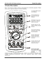
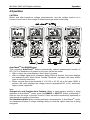
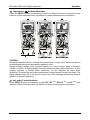
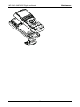
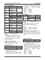
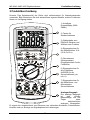
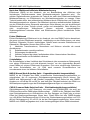
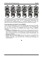
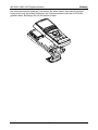
3 Product Description
Note: Top of the line model is used as representative for illustration purposes. Please
refer to your respective model for function availability.
1) 4 digits 9999 counts
dual displays
2) Push-buttons for
special functions &
features
3) Selector to turn the
Power On or Off and
Select a function
4) Input Jack for 10A
(20A for 30sec) current
function
5) Common (Ground
reference) Input Jack
for all functions
6) Input Jack for all
functions EXCEPT
current (μA, mA, A)
functions
7) Input Jack for milli-
amp and micro-amp
current functions
Analog bar-graph
The analog bar graph
provides a visual
indication of
measurement like a traditional analog meter needle. It is excellent in detecting faulty
contacts, identifying potentiometer clicks, and indicating signal spikes during
adjustments.

MD 9040 & MD 9050 Digital multimeter Product Description
7
Average sensing RMS calibrated
RMS (Root-Mean-Square) is the term used to describe the effective or equivalent DC
value of an AC signal. Most digital multimeters use average sensing RMS calibrated
technique to measure RMS values of AC signals. This technique is to obtain the
average value by rectifying and filtering the AC signal. The average value is then scaled
upward (calibrated) to read the RMS value of a sine wave. In measuring pure sinusoidal
waveform, this technique is fast, accurate and cost effective. In measuring non-
sinusoidal waveforms, however, significant errors can be introduced because of
different scaling factors relating average to RMS values.
True RMS
True RMS is a term which identifies a DMM that responds accurately to the effective
RMS value regardless of the waveforms such as: square, sawtooth, triangle, pulse
trains, spikes, as well as distorted waveforms with the presence of harmonics.
Harmonics may cause :
1) Overheated transformers, generators and motors to burn out faster than normal
2) Circuit breakers to trip prematurely
3) Fuses to blow
4) Neutrals to overheat due to the triplen harmonics present on the neutral
5) Bus bars and electrical panels to vibrate
Crest Factor
Crest Factor is the ratio of the Crest (instantaneous peak) value to the True RMS value,
and is commonly used to define the dynamic range of a True RMS DMM. A pure
sinusoidal waveform has a Crest Factor of 1.4. A badly distorted sinusoidal waveform
normally has a much higher Crest Factor.
NMRR (Normal Mode Rejection Ratio)
NMRR is the DMM's ability to reject unwanted AC noise effect that can cause
inaccurate DC measurements. NMRR is typically specified in terms of dB (decibel). This
series has a NMRR specification of >60dB at 50 and 60Hz, which means a good ability
to reject the effect of AC noise in DC measurements.
CMRR (Common Mode Rejection Ratio)
Common mode voltage is voltage present on both the COM and VOLTAGE input
terminals of a DMM, with respect to ground. CMRR is the DMM's ability to reject
common mode voltage effect that can cause digit rolling or offset in voltage
measurements. This series has a CMRR specifications of >60dB at DC to 60Hz in ACV
function; and >120dB at DC, 50 and 60Hz in DCV function. If neither NMRR nor CMRR
specification is specified, a DMM's performance will be uncertain.

MD 9040 & MD 9050 Digital multimeter Operation
8
4 Operation
CAUTION
Before and after hazardous voltage measurements, test the voltage function on a
known source such as line voltage to determine proper meter functioning.
AutoCheckTM (for MD9050 only)
This innovative AutoCheckTM feature automatically selects measurement function of
DCV, ACV or Resistance (Ω) based on the input via the test leads.
• With no input, the meter displays “Auto” when it is ready.
• With no voltage signal but a resistance below 60MΩ is present, the meter displays
the resistance value. When below “Audible Threshold“ is present, the meter further
gives a continuity beep tone.
• When a signal above the threshold of 1.5V DC or 3V AC up to the rated 1000V is
present, the meter displays the voltage value in appropriate DC or AC, whichever
larger in peak magnitude.
Note:
*Range-Lock and Function-Lock Feature: When a measurement reading is being
displayed in AutoCheckTM mode, press the RANGE or SELECT button momentarily 1
time can lock the range or function it was in. Press the button momentarily repeatedly to
step through the ranges or functions.
*As Hazardous-Alert: When making resistance measurements in AutoCheckTM mode,
an unexpected display of voltage readings alerts you that the object under test is being
energized.

MD 9040 & MD 9050 Digital multimeter Operation
9
*Ghost-voltage Buster: Ghost-voltages are unwanted stray signals coupled from
adjacent hard signals, which confuse common multimeter voltage measurements. Our
AutoCheckTM mode provides low (ramp-up) input impedance (approx. 3kΩ at low
voltage) to drain ghost voltages leaving mainly hard signal values on meter readings. It
is an invaluable feature for precise indication of hard signals, such as distinguishing
between hot and open wires (to ground) in electrical installation applications.
WARNING:
AutoCheckTM mode input impedance increases abruptly from initial 3kΩ to a few
hundred kΩ’s on high voltage hard signals. “LoZ” displays on the LCD to remind the
users of being in such low impedance mode. Peak initial load current, while probing
1000VAC for example, can be up to 471mA (1000V x 1.414 / 3kΩ), decreasing abruptly
to approx. 3.1mA (1000V x 1.414 / 460kΩ) within a fraction of a second. Do not use
AutoCheckTM mode on circuits that could be damaged by such low input impedance.
Instead, use rotary selector or high input impedance voltage modes to minimize
loading for such circuits.
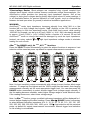
dBm +Hz (for MD9050 only), Hz +ACV, ACV +Hz functions
Press the SELECT button momentarily to select the subject functions in sequence. Last
selection will be saved as power up default for repeat measurement convenience.
Note: Hz Input sensitivity varies automatically with voltage (current function alike) range
selected. 1V range has the highest and the 1000V range has the lowest. Auto-ranging
measurements normally set the most appropriate trigger level. You can also press the
RANGE button momentarily to select another trigger level (voltage range) manually. If
the Hz reading becomes unstable, select higher voltage range to avoid electrical noise.
If the reading shows zero, select lower voltage range.
Note: In dBm +Hz function, power up default reference impedance will be displayed for 1
second before displaying the dBm readings. Press dBm-Ω (RANGE) button momentary
to select different reference impedance of 4, 8, 16, 32, 50, 75, 93, 110, 125, 135, 150,
200, 250, 300, 500, 600, 800, 900, 1000, up to 1200Ω. Last selection will be saved as
power up default for repeat measurement convenience. Manual trigger level selection
on Hz reading is not available.

MD 9040 & MD 9050 Digital multimeter Operation
10
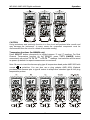
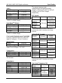
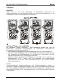
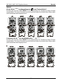
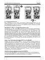
DC+ACV +ACV(MD9050 only), DCV, DCV +ACV functions
Press the SELECT button momentarily to select the subject functions in sequence. Last
selection will be saved as power up default for repeat measurement convenience.
MD9050
DCmV, DCmV +ACmV, DC+ACmV +ACmV, Logic-Level Hz & Duty%
Press the SELECT button momentarily to select the subject functions in sequence. Last
selection will be saved as power up default for repeat measurement convenience.
MD9040
DCmV, DCmV +ACmV, Logic-Level Hz & Duty%
Press the SELECT button momentarily to select the subject functions in sequence. Last
selection will be saved as power up default for repeat measurement convenience.

MD 9040 & MD 9050 Digital multimeter Operation
11
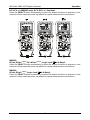
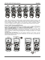
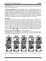
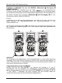
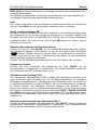
ACmV +Hz, dBm +Hz(MD9050 only), Hz +ACmV functions
Press the SELECT button momentarily to select the subject functions in sequence. Last
selection will be saved as power up default for repeat measurement convenience.
nS Conductance (MD9050 only), Ω Resistance, Continuity functions
Press the SELECT button momentarily to select the subject functions in sequence for
MD9050. Last selection will be saved as power up default for repeat measurement
convenience. Direct rotary switch selection on Ω Resistance and Continuity
functions for the MD9040
Note: Conductance is the inverse of Resistance, that is S=1/Ω or nS=1/GΩ. It virtually
extends the Resistance measurements to the order of Giga-Ohms for leakage
measurements.
Continuity function is convenient for checking wiring connections and operation of
switches. A continuous beep tone indicates a complete wire.

MD 9040 & MD 9050 Digital multimeter Operation
12
CAUTION
Using resistance and continuity function in a live circuit will produce false results and
may damage the instrument. In many cases the suspected component must be
disconnected from the circuit to obtain an accurate reading
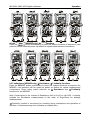
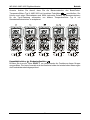
Temperature functions (for MD9050 only)
Press SELECT button momentarily to toggle between °C and °F readings. For Dual
Channel Temperature function on the MD9050, press T1-T2 (RANGE) button
momentarily can select T1, T2, T1 +T2 or T1-T2 +T2 readings. Last selection will be saved
as power up default for repeat measurement convenience.
Note: Be sure to insert the banana plug type-K temperature bead probe AMD 9023 with
correct polarities. You can also use a plug adapter AMD 9024 (Optional
purchase) with banana pins to type-K socket to adapt other standard type-K mini plug
temperature probes.

MD 9040 & MD 9050 Digital multimeter Operation
13
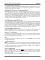
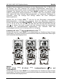
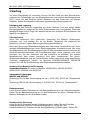
Capacitance, Diode test functions
Press the SELECT button momentarily to select the subject functions in sequence. Last
selection will be saved as power up default for repeat measurement convenience.
CAUTION
Discharge capacitors before making any measurement. Large value capacitors should
be discharged through an appropriate resistance load.
Normal forward voltage drop (forward biased) for a good silicon diode is between
0.400V to 0.900V. A reading higher than that indicates a leaky diode (defective). A zero
reading indicates a shorted diode (defective). An OL indicates an open diode
(defective). Reverse the test leads connections (reverse biased) across the diode. The
digital display shows OL if the diode is good. Any other readings indicate the diode is
resistive or shorted (defective).
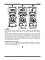
μA, mA, and A Current functions
Press SELECT button momentarily to select DC, DC +AC, DC+AC +AC and AC +Hz. Last
selection will be saved as power up default for repeat measurement convenience.

MD 9040 & MD 9050 Digital multimeter Operation
14
*Note: When measuring a 3-phase system, special attention should be taken to the
phase-to-phase voltage which is significantly higher than the phase-to-earth voltage. To
avoid exceeding the voltage rating of the protection fuse(s) accidentally, always
consider the phase-to-phase voltage as the working voltage for the protection fuse(s).
Electric Field EF-Detection (MD9050 only)
At any function, press the EF button for one second or more to toggle to EF-Detection
feature. The meter displays “E.F.” when it is ready. Signal strength is indicated as a
series of bar-graph segments on the display plus variable beep tones.
●Non-Contact EF-Detection: An antenna is located along the top of the meter, which
detects electric field surrounds current-carrying conductors. It is ideal for tracing live
wiring connections, locating wiring breakage and to distinguish between live or earth
connections.
●Probe-Contact EF-Detection: For more precise indication of live wires, such as
distinguishing between live and ground connections, use the Red (+) test probe for
direct contact measurements.

MD 9040 & MD 9050 Digital multimeter Operation
15
PC computer interface capabilities
The instrument equips with an optical isolated interface port at the meter back for data
communication. Optional purchase PC USB interface kit AMD9050 is required to
connect the meter to the PC computer.
MAX/MIN/AVG* (REC) at fast 20/s measurement mode
Press REC button momentarily to activate MAX/MIN/AVG* recording mode. The LCD
“R” & “MAX MIN AVG*” turn on, and the reading update rate will be increased to
20/second. The meter beeps when new MAX (maximum) or MIN (minimum) reading is
updated. AVG* (Average) reading is calculated over time. Press the button momentarily
to read the MAX, MIN, MAX-MIN and AVG* readings in sequence. Press the button for
1 second or more to exit MAX/MIN/AVG* recording mode. Auto-ranging remains, and
Auto-Power-Off is disabled automatically in this mode.
1ms CREST capture mode (MD9050 only)
Press CREST button momentarily to activate CREST (Instantaneous Peak-Hold) mode
to capture voltage or current signal duration as short as 1ms. The LCD “C” & “MAX” turn
on. The meter beeps when new MAX (maximum) or MIN (minimum) reading is updated.
Press the button momentarily to read the MAX , MIN, and MAX-MIN (Vp-p) readings in
sequence. Press the button for 1 second or more to exit CREST mode. Auto-ranging
(up range) remains, and Auto-Power-Off is disabled automatically in this mode.
Backlighted display (MD9050 only)
Press the SELECT button for 1 second or more to toggle the LCD backlight. The
backlight will also be turned off automatically after 32 seconds to extend battery life.
Beep-Jack™ Input Warning
The meter beeps as well as displays “InEr” to warn the user against possible damage to
the meter due to improper connections to the μA, mA, or A input jacks when other
function (like voltage function) is selected.
Hold
The hold feature freezes the display for later view. Press the HOLD button momentarily
to toggle the hold feature.
Relative Zero mode
Relative zero allows the user to offset the meter consecutive measurements with the
displaying reading as the reference value. Practically all displaying readings can be set
as relative reference value including MAX/MIN/AVG* readings. Press the button
momentarily to toggle relative zero mode.
Manual or Auto-ranging
Press the RANGE button momentarily to select manual-ranging, and the meter will
remain in the range it was in, the LCD turns off. Press the button momentarily
again to step through the ranges. Press and hold the button for 1 second or more to
resume auto-ranging.
Note: Manual ranging feature is not available in Hz function.

MD 9040 & MD 9050 Digital multimeter Operation
16
Set Beeper Off
Press the RANGE button while turning the meter on to temporarily disable the Beeper
feature. Turn the rotary switch OFF and then back on to resume.
Auto-Power-off (APO)
The Auto-Power-off (APO) mode turns the meter off automatically to extend battery life
after approximately 30 minutes of no activities. Activities are specified as: 1) Rotary
switch or push button operations, and 2) Significant measuring readings of above 512
counts or non-OL Ω readings. In other words, the meter will intelligently avoid entering
the APO mode when it is under normal measurements.. To wake up the meter from
APO, press the SELECT, RANGE, RELATIVE or HOLD button momentarily or turn the
rotary switch OFF and then back on. Always turn the rotary switch to the OFF position
when the meter is not in use
Disabling Auto-Power-off
Press the SELECT button while turning the meter on to temporarily disable the Auto-
Power-Off feature. Turn the rotary switch OFF and then back on to resume.

MD 9040 & MD 9050 Digital multimeter Maintenance
17
5 Maintenance
WARNING
To avoid electrical shock, disconnect the meter from any circuit, remove the test leads
from the input jacks and turn OFF the meter before opening the case. Do not operate
with open case. Install only the same type of fuse or equivalent
Cleaning and Storage
Periodically wipe the case with a damp cloth and mild detergent; do not use abrasives
or solvents. If the meter is not to be used for periods of longer than 60 days, remove the
battery and store it separately
Trouble Shooting
If the instrument fails to operate, check battery, fuses, leads, etc., and replace as
necessary. Double check operating procedure as described in this user’s manual
If the instrument voltage-resistance input terminal has subjected to high voltage
transient (caused by lightning or switching surge to the system) by accident or abnormal
conditions of operation, the series fusible resistors will be blown off (become high
impedance) like fuses to protect the user and the instrument. Most measuring functions
through this terminal will then be open circuit. The series fusible resistors and the spark
gaps should then be replaced by qualified technician. Refer to the LIMITED
WARRANTY section for obtaining warranty or repairing service.
Battery and Fuse replacement
Battery use: Single 9V battery; NEDA1604G, JIS006P IEC6F22, NEDA1604A,
JIS6AM6 or IEC6LF22
Fuses use:
MD 9040 and 9050:
Fuse (FS1) for μAmA current input: 1A/600Vac, IR 100kA, F fuse;
Fuse (FS2) for A current input: 10A/600Vac, IR 100kA, F fuse
Battery replacement:
Loosen the 2 screws from the battery access door of the case bottom. Lift the battery
access door and thus the battery compartment up. Replace the battery. Re-fasten the
screws.
Fuse replacement:
Loosen the 4 screws from the case bottom. Lift the end of the case bottom nearest the
input jacks until it unsnaps from the case top. Replace the blown fuse(s). Replace the
case bottom, and ensure that all the gaskets are properly seated and the two snaps on
the case top (near the LCD side) are engaged. Re-fasten the screws.

MD 9040 & MD 9050 Digital multimeter Maintenance
18

MD 9040 & MD 9050 Digital multimeter Specification
19
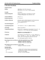
6 Specification
General Specifications
Display: 9999 counts: ACV, DCV, Hz & nS
6000 counts: mV, μA, mA, A, Ohm & Capacitance
Polarity: Automatic
Update Rate: Digital Display: 5 per second nominal;
41 Segments Bar-graph: 60 per second max
Low Battery: Below approx. 7V
Operating Temperature: 0oC to 45oC
Relative Humidity: Maximum relative humidity 80% for temperature up to 31oC
decreasing linearly to 50% relative humidity at 45oC
Pollution degree: 2
Storage Temperature: -20oC to 60oC, < 80% R.H. (with battery removed)
Altitude: Operating below 2000m
Temperature Coefficient: nominal 0.15 x (specified accuracy)/ oC @(0oC ~ 18oC or
28oC ~ 45oC), or otherwise specified
Sensing: MD 9050: AC+DC True RMS
MD 9040: AC True RMS
Safety: Double insulation per IEC61010-1 2nd Ed., EN61010-1 2nd
Ed., UL61010-1 2nd Ed. & CAN/CSA C22.2 No. 61010.1-
0.92 to Category IV 1000Vac & Vdc.
Transient protection: 12kV (1.2/50μs surge)
MD 9040 & MD 9050 Terminals (to COM) Measurement Category:
V : Category IV 1000Vac & Vdc
mAμA : Category IV 600Vac and 300Vdc
A : Category IV 600Vac and 500Vdc
Overload Protections:
MD 9050, MD 9040:
μA & mA: 1A/600Vac, IR 100kA, F fuse
A: 10A/600Vac, IR 100kA, F fuse
V: 1050Vrms, 1450Vpeak
mV, Ω, & Others: 600Vdc and Vac rms
E.M.C. : Meets EN61326-1:2006 (EN55022, EN61000-3-2, EN61000-
3-3, EN61000-4-2, EN61000-4-3, EN61000-4-4, , EN61000-
4-5, EN61000-4-6, EN61000-4-8, EN61000-4-11)
In an RF field of 3V/m:
Capacitance function is not specified

MD 9040 & MD 9050 Digital multimeter Specification
20
Other function ranges:
Total Accuracy = Specified Accuracy + 100 digits
Performance above 3V/m is not specified
Power Supply: Single 9V battery; NEDA1604G, JIS006P IEC6F22,
NEDA1604A, JIS6AM6 or IEC6LF22
Power Consumption: 5 mA typical
APO Timing: Idle for 30 minutes
APO Consumption: 50μA typical
Dimension: L208mm X W103mm X H64.5mm with holster
Weight: 635 gm with holster
Accessories: Test lead pair; battery installed; user’s manual; AMD9023
banana plug type-K thermocouple (MD 9050)
Optional purchase accessories: USB interface kit AMD9050; AMD9024 banana plug to type-
K socket plug adaptor
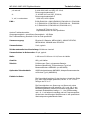
Electrical Specifications Accuracy is ±(% reading digits + number of digits) or
otherwise specified, at 23oC ± 5oC & less than 75% relative
humidity.
True RMS voltage & current accuracies are specified from 10 % to 100 % of range or otherwise
specified. Maximum Crest Factor < 3:1 at full scale & < 6:1 at half scale, and with frequency
components within the specified frequency bandwidth for non-sinusoidal waveforms.

MD 9040 & MD 9050 Digital multimeter Specification
21
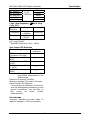
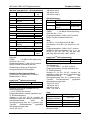
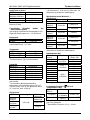
AC & AC+DC Voltage
Function RANGE Accuracy
50Hz ~ 60Hz
mV 60.00mV,
600.0mV
V 9.999V, 99.99V,
999.9V
0.5% + 3d
40Hz ~ 500Hz
mV 60.00mV,
600.0mV 0.8% + 4d
9.999V, 99.99V 1.0%+4d V
999.9V 2.0%+4d
500Hz ~ 1kHz
mV 60.00mV,
600.0mV 2.0% + 3d
9.999V, 99.99V 1.0%+4d V
999.9V 2.0%+4d
1kHz ~ 3kHz
mV 60.00mV,
600.0mV 2%+3d
V 9.999V, 99.99V,
999.9V 3.0%+4d
3kHz ~ 20kHz
mV 60.00mV 1),
600.0mV 1) 2%+3d
9.999V, 99.99V 3dB V
999.9V Unspec’d
1)Specificied from 30% to 100% of range.
CMRR: >60dB @ DC to 60Hz,
Rs=1kΩ
Input Impedance: 10MΩ, 50pF nominal
(80pF nominal for 600mV range)
Residual reading less than 5 digits with
test leads shorted.
Audible Continuity Tester
Audible threshold: between 20Ω and
300Ω; Response time < 100μs
AutoCheckTM (ACV)
RANGE 1) Accuracy
50Hz ~ 60Hz
9.999V, 99.99V, 999.9V 1.0%+4d
Lo-Z ACV Threshold:
> 3VAC (50/60Hz) nominal
Lo-Z ACV Input Impedance:
Initially approx. 3.0kΩ, 150pF nominal;
Impedance increases abruptly within a
fraction of a second as display voltage
is above 50V (typical). Ended up
impedances vs display voltages
typically are:
18kΩ @100V
125kΩ @ 300V
320kΩ @ 600V
460kΩ @ 1000V
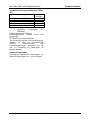
DC Voltage
Function RANGE Accuracy
60.00mV 0.12%+2d mV
600.0mV 0.06%+2d
V 9.999V, 99.99V,
999.9V 0.08%+2d
NMRR: >60dB @ 50/60Hz
CMRR: >110dB @ DC, 50/60Hz,
Rs=1kΩ
Input Impedance: 10MΩ, 50pF nominal
(80pF nominal for 600mV range)
dBm
At 600Ω, -11.76dBm to 54.25dBm,
Accuracy: ± 0.25dB + 2d (@40Hz --
20kHz)
Input Impedance: 10MΩ, 50pF nominal
Selectable reference impedance of 4, 8,
16, 32, 50, 75, 93, 110, 125, 135, 150,
200, 250, 300, 500, 600, 800, 900, 1000,
1200Ω
AutoCheckTM (DCV)
RANGE Accuracy
9.999V, 99.99V, 999.9V 0.5%+3d
Lo-Z DCV Threshold:
> +1.5VDC or < -1.0VDC nominal
Lo-Z DCV Input Impedance:
Initially approx. 3.0kΩ, 165pF nominal;
Impedance increases abruptly within a
fraction of a second as display voltage
is above 50V (typical). Ended up
impedances vs display voltages
typically are:
18kΩ @100V
125kΩ @ 300V
320kΩ @ 600V
500kΩ @ 1000V
Seite wird geladen ...
Seite wird geladen ...
Seite wird geladen ...
Seite wird geladen ...
Seite wird geladen ...
Seite wird geladen ...
Seite wird geladen ...
Seite wird geladen ...
Seite wird geladen ...
Seite wird geladen ...
Seite wird geladen ...
Seite wird geladen ...
Seite wird geladen ...
Seite wird geladen ...
Seite wird geladen ...
Seite wird geladen ...
Seite wird geladen ...
Seite wird geladen ...
Seite wird geladen ...
Seite wird geladen ...
Seite wird geladen ...
Seite wird geladen ...
Seite wird geladen ...
Seite wird geladen ...
Seite wird geladen ...
-
 1
1
-
 2
2
-
 3
3
-
 4
4
-
 5
5
-
 6
6
-
 7
7
-
 8
8
-
 9
9
-
 10
10
-
 11
11
-
 12
12
-
 13
13
-
 14
14
-
 15
15
-
 16
16
-
 17
17
-
 18
18
-
 19
19
-
 20
20
-
 21
21
-
 22
22
-
 23
23
-
 24
24
-
 25
25
-
 26
26
-
 27
27
-
 28
28
-
 29
29
-
 30
30
-
 31
31
-
 32
32
-
 33
33
-
 34
34
-
 35
35
-
 36
36
-
 37
37
-
 38
38
-
 39
39
-
 40
40
-
 41
41
-
 42
42
-
 43
43
-
 44
44
-
 45
45


METREL EDMD9040 Benutzerhandbuch
- Kategorie
- Messen, Testen
- Typ
- Benutzerhandbuch
in anderen Sprachen
- English: METREL EDMD9040 User manual