
Page 1 of 1
KATHREIN Digital Systems GmbH • Anton-Kathrein-Straße 1–3 • 83022 Rosenheim • Germany
Rosenheim, 31.03.2019
Information über gesellschaftsrechtliche Änderung
Information about change in corporate legal status
Zum 1. April 2019 geht das Geschäftsfeld „Terrestrial & Satellite Reception“ der
KATHREIN SE (vormals KATHREIN-Werke KG) auf die KATHREIN Digital Systems
GmbH über.
Die neuen Firmendaten lauten ab 01.04.2019 wie folgt:
KATHREIN Digital Systems GmbH
Anton-Kathrein-Str. 1–3
83022 Rosenheim, Deutschland
Steuer-Nr.: 156/117/31083
UST-Ident-Nr.: DE311049363
Registergericht: Traunstein, HRB 25841
______________________________________________________________________________
As of 1 April 2019, KATHREIN SE’s (formerly KATHREIN-WERKE KG) “Terrestrial &
Satellite Reception” business unit will be transferred to KATHREIN Digital Systems
GmbH (limited liability company).
From 1 April 2019, the new company data are:
KATHREIN Digital Systems GmbH
Anton-Kathrein-Str. 1–3
83022 Rosenheim, Germany
Tax ID No.: 156/117/31083
VAT Reg. No.: DE311049363
Commercial Register: Traunstein, HRB 25841
KATHREIN
Digital Systems GmbH
Anton
-Kathrein-Straße 1–3
83022 Rosenheim
Germany
www.kathrein
-ds.com
info
@kathrein-ds.com
Executive Board
:
Michael Auer
Uwe Thumm
US
t-ID-Nr.: DE 311 049 363
Steuer
-Nr.: 156/117/31083
GLN:
40 63242 00000 5
WEEE
-Reg.-Nr.: DE 66199153
Registered Office: Rosenheim, DE
Commerc
ial Register: Traunstein, HRB 25841
Commerzbank AG
IBAN:
DE24 7114 0041 0611 9002 00
BIC:
COBADEFFXXX
936500001

1 / 4
ESO 005 23710022
Temperatursteuerung ESO005
Zu dieser Anleitung
Dieses Dokument ist Teil des Produkts. Diese Anleitung beschreibt, wie Sie die Temperatursteuerung ESO005 instal-
lieren und anschließen.
► Das Gerät erst installieren und benutzen, nachdem Sie dieses Dokument gelesen und verstanden haben.
► Dieses Dokument während der Lebensdauer des Geräts aufbewahren. Das Dokument an nachfolgende Besitzer und
Benutzer weitergeben.
Die aktuelle Version dieses Anwendungshinweises nden Sie auf der Kathrein-Webseite
www.kathrein.com.
Merkmale
■ Zweipunkt-Temperaturregler im Aufbaugehäuse
■ Kabelverschraubungen und Klemmen für den Elektroanschluss
■ automatische Abschaltung bei Fühlerunterbrechung oder -kurzschluss
■ Einschalttemperatur bei +3ºC
Lieferumfang
● 1xTemperatursteuerung ESO005
● 1xTemperaturfühler PT100
● 10xKabelbinder 360mm
● 1xMontageplatte
● 1xBefestigungsspannband
Transport und Lagerung
► Das Gerät in der Originalverpackung transportieren und lagern.
► Das Gerät im zulässigen Temperaturbereich von –30 bis +80 °C transportieren und lagern. Darauf achten, dass kein
Kondenswasser gebildet wird.
Bestimmungsgemäßer Gebrauch
Die ESO005 ist eine elektronische Temperatursteuerung für Reektorheizungen ESO95 und ESO120. Die ESO005 wird
für Frostschutzheizungen als Luftthermostat oder Oberächenthermostat mit Fernfühler eingesetzt.
Jegliche anderweitige Nutzung oder die Nichtbeachtung dieses Anwendungshinweises und der den Geräten beilie-
genden Dokumentationen und Anleitungen hat den Verlust der Gewährleistung bzw. Garantie zur Folge.
Folgende Sachverhalte führen zum Verlust von Garantie- und Haftungsansprüchen gegenüber dem Hersteller:
● unsachgemäße Montage
● Verwendung von nicht aufgeführtem Befestigungsmaterial, wodurch die mechanische Sicherheit nicht gewährleistet
werden kann
● bauliche Veränderungen oder Eingriffe an den Bestandteilen und dem Befestigungszubehör des Sets, wodurch
sowohl die mechanische und elektrische als auch die funktionelle Sicherheit gefährdet werden kann
● Missachtung der Montage- und Sicherheitshinweise in dieser Anleitung
Tipp
Bewahren Sie die Anleitung für später auftretende Fragen sorgfältig auf und geben Sie diese bei Weitergabe
des Geräts an den nächsten Besitzer weiter.
Funktionsbeschreibung
Liegt die vom Fühler gemessene Temperatur unterhalb des fest eingestellten Sollwertes von +3 ºC, schließt der Relais-
kontakt und die Heizung wird eingeschaltet. Bei Fühlerunterbrechung oder Fühlerkurzschluss wird die Heizung abge-
schaltet.

2 / 4
Montage- und Sicherheitshinweise
GEFAHR
Lebensgefahr durch Stromschlag!
► Bei Montage alle angeschlossenen Geräte vom Stromnetz trennen.
► Einen Fehlerstrom-Schutzschalter mit einem Nennfehlerstrom von 0,03A vorschalten lassen, um die
Vorschriften für Außenanlagen nach DINVDE0100Teil610 einzuhalten.
► Sicherstellen, dass die Montage und der Anschluss nur von qualiziertem Fachpersonal ausgeführt werden.
► Veränderungen der Elektroinstallation nur von einem Fachmann vornehmen lassen. Niemals eigenmächtige
Veränderungen vornehmen.
WARNUNG
Gefahr schwerer Verletzung bei Montagearbeiten durch Absturz, möglichen Durchbruch oder herabfal-
lende Teile
► Feste und rutschsichere Schuhe tragen.
► Arbeitsbühne verwenden.
► Sicherstellen, dass die montierende/reparierende Person eine sichere Stand- und Halteposition hat.
► Sicherstellen, dass die montierende/reparierende Person schwindelfrei ist und sich sicher auf dem Dach
oder Montageort bewegen kann.
► Sicherstellen, dass das Dach ausreichend stabil ist.
► Sicherstellen, dass sich während der Montage niemand im Bereich unterhalb der Antenne bendet.
► Sicherstellen, dass das Dach und die Aufstiegshilfe trocken, sauber und rutschfest sind.
Temperatursteuerung montieren und anschließen
Erforderliche Werkzeuge und Hilfsmittel
● Schlitzschraubendreher
● Kältespray für Funktionstest
● Spitzzange, kann optional zum Anschließen der Kabel
verwendet werden
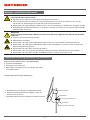
Temperatursteuerung montieren
1. Spannband mit dem Schlitzschraubendreher öffnen.
2. Temperatursteuergerät ESO005 möglichst hoch am
Antennenmast ansetzen.
3. Spannband durch Drehen der Spannschraube festziehen.
Antennenmast
Spannband
Temperatursteuerung
Netzkabel
Kabel von der Heizschale

3 / 4
Kabel anschließen
ACHTUNG
Gefahr der Beschädigung des Geräts!
► Vor Anschluss der Kabel im Steuergerät die Beheizung auf Durchgangs- und Isolationswiderstand (R
i
)
prüfen. Die Sollwerte der Anleitung der Reektorheizung entnehmen.
► Diese Prüfung auch nach dem Austausch einer defekten Heizschale durchführen.
1. Anschlusskabel der Heizschale am Antennenmast entlang zum Steuergerät ESO005 führen.
2. Anschlusskabel mit Kabelbindern befestigen.
3. Anschlusskabel von unten durch die Verschraubung in das Steuergerät einführen.
4. Netzkabel von unten durch die Verschraubung in das Steuergerät einführen.
5. Bei Verwendung der Temperatursteuerung ESO005 die Kabel gemäß Abb. 1 anschließen,
bei Betrieb der Heizung ohne ESO005 die Kabel gemäß Abb. 2 anschließen.
1 2 3 4 5 6 87 9 10 11 12
PT 100 PE N |opt.| L L N PE
Heizung
Heater
Chauffage
Netz
Mains
Reseau
C
Abb. 1: Anschlussbelegung Temperatursteuerung ESO005
bl: 0 V
bn: 230 V
gn/gb: PE
Netzkabel
Kabel von der
Heizschale
Abb. 2: Anschlussbelegung bei Betrieb der Heizung ohne ESO005

4 / 4
www.kathrein.com | [email protected]
KATHREIN-Werke KG, Anton-Kathrein-Straße 1-3, 83022 Rosenheim, Germany, Telefon +49 8031 184-0, Fax +49 8031 184-52360
936.5141/-/PSA/1216/DE | Änderungen vorbehalten.
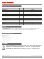
Technische Daten
Typ Einheit ESO005
Bestellnummer 23710022
Gehäusewerkstoff Polycarbonat
Kabeleinführung 1xM12, 2xM25
Messeingang PT100 Temperaturfühler
Empfohlene Montagetemperatur ºC 5–20
Umgebungstemperatur ºC –30–+80
Betriebsspannung V 230 +6%/–10%; 50–60Hz
Schaltleistung 16A/230V
Einstellbereich ºC 3
Schutzart IP66
Abmessungen (HxBxT) mm 130x130x75
Gewicht g 530
Wartung
► In regelmäßigen Abständen die einwandfreie Befestigung und den festen Sitz der Temperatursteuerung an der
Antenne kontrollieren.
► Bei Temperaturen über +5ºC ein Kältespray auf den Fühler sprühen, damit die Heizung einschaltet.
Reparatur und Austausch
Rep and More GmbH
Hauptstrasse 2a
35792 Löhnberg-Oberhausen
Telefon: +49 6477 6123-101
Fax: +49 6477 6123-020
E-Mail:
info@repandmore.com
Entsorgung
Elektronische Geräte gehören nicht in den Hausmüll, sondern müssen – gemäß Richtlinie 2002/96/EG DES
EUROPÄISCHEN PARLAMENTS UND DES RATES vom 27. Januar 2003 – über Elektro- und Elektronik-
Altgeräte fachgerecht entsorgt werden.
Bitte geben Sie dieses Gerät am Ende seiner Verwendung zur Entsorgung an den dafür vorgesehenen
öffentlichen Sammelstellen ab.

1 / 4
ESO 005 23710022
ESO 005 Temperature Control
About This Guide
This document is part of the product. This document describes how to install and connect the ESO005 temperature
control.
► Do not install or use the device until you have read and understood this document.
► Keep this document for reference throughout the service life of the device. Pass this document on to any new owner
or user.
For the most up-to-date version of this document, go to the Kathrein website
www.kathrein.com.
Features
■ Dual mode temperature controller in the surface-mount housing
■ Cable glands and clamps for the power supply
■ Automatic switch-off if the sensor is disconnected or in case of a short circuit
■ Switch-on temperature at +3ºC
Scope of Delivery
● 1 x ESO005 temperature control
● 1 x PT100 temperature sensor
● 10xcable ties, 360mm
● 1xmounting plate
● 1xtightening strap
Transport and Storage
► Transport and store the device in its original packaging.
► Transport and store the device only in the permitted temperature range between –30 and +80 °C. Make sure there is
no water condensation build-up.
Intended Use
The ESO005 is an electronic temperature control for the ESO95 and ESO120 reflector heating systems. The ESO005
is designed for use as an ambient thermostat for frost protection heating systems and surface thermostat with remote
sensor.
Any other use, or failure to comply with these instructions or documentation and instructions enclosed with the devices,
will result in voiding of warranty or guarantee.
The following circumstances result in the loss of all warranty and liability claims towards the manufacturer:
● Improper Installation
● Use of non-specified mounting materials, which cannot guarantee the mechanical reliability of the antenna system
● Structural changes or interference with the components and mounting accessories in the kit, which could endanger
both the mechanical and functional reliability
● Failure to observe installation and safety instructions in this manual
Tip
Keep these instructions for further reference, and if the unit passes to another owner, pass them on to the
new owner.
Functional Specification
If the temperature measured by the sensor lies below the fixed set point of +3 ºC, the relay closes and the heating
switches on. The heating is switched off if the sensor is disconnected or in case of a short circuit.

2 / 4
Installation and Safety Instructions
DANGER
Danger to life from electric shock!
► Disconnect all devices and units from the power supply during installation.
► In order to comply with the regulations for outdoor installation according to DINVDE0100Part610, it is
recommended to have a residual current circuit breaker with a residual current of 0.03 A installed upstream.
► Make sure that modifications to electrical installations are only carried out by a specialist.
► Make sure that modifications to electrical installations are only carried out by a specialist. Do not make any
unauthorised changes yourself.
WARNING
Risk of severe injuries during installation due to falling from the roof, falling through the roof and falling
parts!
► Wear stable shoes with non-slip soles.
► Use a working platform.
► Make sure that the person carrying out the installation or repair has a secure position to stand and hold on
whilst working.
► Make sure that the person carrying out the installation or repair does not suffer from vertigo and can move
around safely on the installation site.
► Make sure that the vehicle roof is sufficiently strong and stable.
► Make sure that there is nobody underneath the antenna during installation/dismantling.
► Make sure that the roof and climbing aid are dry, clean and non-slip.
Installing and Connecting the Temperature Control
Required Tools and Equipment
● Flat screwdriver
● Cooler spray for a performance check
● Needle-nose pliers, optional, to connect the cables
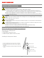
Installing the Temperature Control
1. Open the tightening strap using the flat screwdriver.
2. Place the ESO 005 on the antenna mount as high as
possible.
3. Tighten the tightening strap by rotating the tensioning
screw.
Antenna mount
Tightening strap
Temperature control
Power cable
Cable from the heating
tray

3 / 4
Connecting the Cables
NOTICE
Risk of damage to the unit!
► Test the heating for contact resistance and insulation resistance (R
i
) before connecting the cables in the
control device. For target values, see the instructions for use of the reflector heating.
► These tests should be repeated after replacement of a defective heating tray.
1. Run the connection cables of the heating tray along the antenna carrier to the ESO005 control device.
2. Use cable ties to attach the connection cables.
3. Run the cables from the bottom through the screw connection into the control device.
4. Run the mains cable from the bottom through the screw connection into the control device.
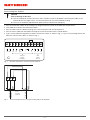
5. If you use the ESO 005 temperature control, connect the cables as shown in Fig. 1, if you use the heating without the
ESO005, connect the cables as shown in Fig. 2 .
1 2 3 4 5 6 87 9 10 11 12
PT 100 PE N |opt.| L L N PE
Heizung
Heater
Chauffage
Netz
Mains
Reseau
C
Fig. 1: ESO005 temperature control terminal assignment
bl: 0 V
bn: 230 V
gn/gb: PE
Power cable
Cable from the
heating tray
Fig. 2: Terminal assignment when using the heating without the ESO005

4 / 4
www.kathrein.com | [email protected]
KATHREIN-Werke KG, Anton-Kathrein-Straße 1-3, 83022 Rosenheim, Germany, Phone +49 8031 184-0, Fax +49 8031 184-52360
936.5141/-/PSA/1216/GB |Subject to change.
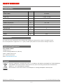
Technical Data
Type Unit ESO005
Order number 23710022
Housing material Polycarbonate
Cable entry 1xM12, 2xM25
Measuring input PT100 temperature sensor
Recommended installation temperature ºC 5–20
Ambient temperature ºC –30–+80
Operating voltage V 230 +6%/–10%; 50–60Hz
Breaking capacity 16A/230V
Setting range ºC 3
Protection class IP66
Dimensions (HxWxD) mm 130 x 130 x 75
Weight g 530
Maintenance
► Check the correct attachment and seating of the temperature control on the antenna at regular intervals.
► If the temperature is higher than +5ºC, spray a cooler spray onto the sensor for the heating to switch on.
Repair and Replacement
Rep and More GmbH
Hauptstrasse 2a
35792 Löhnberg-Oberhausen, Germany
Phone: +49 6477 6123-101
Fax: +49 6477 6123-020
Email:
info@repandmore.com
Disposal
Electronic equipment is not domestic waste – in accordance with directive 2002/96/EC OF THE EUROPEAN
PARLIAMENT AND THE COUNCIL dated 27th January 2003 concerning used electrical and electronic
appliances, it must be disposed of properly.
At the end of its service life, take this unit for disposal at a designated public collection point.
-
 1
1
-
 2
2
-
 3
3
-
 4
4
-
 5
5
-
 6
6
-
 7
7
-
 8
8
-
 9
9


in anderen Sprachen
- English: Kathrein ESO 005 User manual
Verwandte Papiere
-
Kathrein 23710023 Benutzerhandbuch
-
-
-
Kathrein 20010006 Benutzerhandbuch
-
-
-
-
-
-
Kathrein EXIP 4124 Benutzerhandbuch
