
1
TP 82
Bedienungsanleitung
User Manual
Mode d’Emploi
®

www.thorens.com

Bedienungsanleitung
User Manual
Mode d’Emploi
TP 82

TONARM UND TONABNEHMERSYSTEM 6
AUFLAGEKRAFT 7
AZIMUT 8
ANTISKATINGKRAFT 9
WEITERE TONARMEINSTELLUNGEN 10
TECHNISCHE DATEN 11
Inhalt

BRAS ET CELLULE DE LECTURE 20
FORCE D’APPUI 21
AZIMUT 22
FORCE ANTISKATING 23
AUTRES REGLAGES DU BRAS DE LECTURE 24
CARACTERISTIQUES TECHNIQUES 25
TONEARM AND PICK-UP CARTRIDGE 13
TRACKING FORCE 14
AZIMUTH 15
ANTI-SKATING FORCE (BIAS) 16
FURTHER TONEARM ADJUSTMENTS 17
TECHNICAL SPECIFICATIONS 18
Table of Contents Sommaire

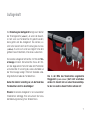
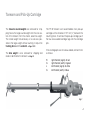
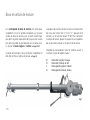
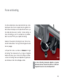
Tonarm und Tonabnehmersystem
Abb. 1
Die Tonarmgewichte sind zum Transport entfernt. Dre-
hen Sie diese zur Montage von hinten auf den Tonarm.
Das kleinere exzentrische Gewicht sollte sich stets so
nah wie möglich hinter dem großen Gewicht befi nden,
ohne dieses jedoch zu berühren. Stellen Sie anschlie-
ßend Au agekraft und Azimut ein. ➔ Seite 7/8
Das Antiskatinggewicht ist ebenfalls zum Transport
entfernt und muss zur Montage am Tonarm eingehängt
werden. ➔ Seite 9
Am Tonarm TP 82 können Tonabnehmer mit einem Ab-
stand der Befestigungslöcher von 12,7 mm (½ ”) mon-
tiert werden. Zum Anschluss des Tonabnehmersystems
werden die vier farblich gekennzeichneten Anschlußlit-
zen auf die entsprechenden Anschluß-Stifte des Tonab-
nehmers geschoben.
Verbinden Sie nach folgendem Schema, falls der Ton-
abnehmer keine Farbkennung aufweist:
R rechter Kanal (Signal) ➔ rot
G rechter Kanal (Masse) ➔ grün
L linker Kanal (Signal) ➔ weiß
G linker Kanal (Masse) ➔ blau
6

7
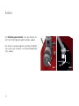
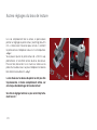
Au agekraft
Die Einstellung der Au agekraft erfolgt durch drehen
der Tonarmgewichte (➔ Abb. 2). Je weiter die Gewich-
te nach vorne zum Tonabnehmer hin gedreht werden,
desto größer wird die Aufl agekraft. Das kleinere, ex-
zentrische Gewicht dient der Einstellung des Azimuts
(➔ Seite 8). Es sollte sich so nah wie möglich hinter dem
größeren Gewicht befi nden, ohne dieses zu berühren.
Die korrekte Aufl agekraft können Sie mit Hilfe der Ton-
armwaage einstellen. Schwenken Sie hierzu den Ton-
arm bei abgesenktem Tonarmlift über den Plattenteller
und senken Sie ihn vorsichtig ab, so dass die Nadel auf
der Tonarmwaage aufl iegt. Entfernen Sie dabei unbe-
dingt die Schutzhaube des Tonabnehmers.
Gehen Sie äußerst vorsichtig vor, um die Nadel des
Tonabnehmers nicht zu beschädigen!
Hinweis: Die korrekte Aufl agekraft ist vom verwendeten
Tonabnehmer abhängig. Bitte konsultieren Sie hierzu
die Bedienungsanleitung Ihres Tonabnehmers.
Abb. 2
Das in der Mitte des Tonarmrohres angebrachte
Ringgewicht (➔ Seite 6, Abb. 1) darf nicht verschoben
werden. Es handelt sich um einen Resonanzdämp-
fer, der nur exakt an dieser Position wirksam ist!

8
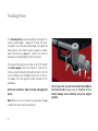
Azimut
Zur Einstellung des Azimuts muss das kleinere, ex-
zentrische Tonarmgewicht gedreht werden. ➔ Abb. 3
Der Azimut ist korrekt eingestellt, wenn das Tonabneh-
mersystem exakt senkrecht zur Plattentelleroberfl äche
steht. ➔ Abb. 4
Abb. 4Abb. 3
90°

9
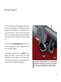
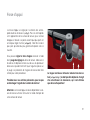
Antiskatingkraft
Durch Zusammenwirken der Reibungskraft der Platten-
rillen mit den Lagerkräften am Tonabnehmer wird beim
Abspielen einer Schallplatte eine Kraftkomponente er-
zeugt, die den Tonarm nach innen zieht: Die Skating-
kraft. Zu ihrer Kompensation dient die Antiskatingkraft,
welche beim Tonarm TP 82 durch ein Gewicht erzeugt
wird.
Der Faden des Antiskatinggewichts wird durch die
Öse am Tonarm geführt und am Einhängestift des Ton-
arms eingehängt (➔ Abb. 5).
Am Einhängestift befi nden sich sechs Rillen zum Ein-
hängen des Gewichts. Je weiter außen das Gewicht
eingehängt wird, desto größer ist die Antiskatingkraft.
Die benötigte Antiskatingkraft ist vom verwendeten Ton-
abnehmer und der Aufl agekraft abhängig.
Abb. 5
Die benötigte Antiskatingkraft ist vom verwendeten
Tonabnehmer abhängig und sollte bei einem Wech-
sel mithilfe einer Meßschallplatte ermittelt werden.

10
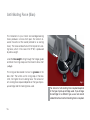
Weitere Tonarmeinstellungen
Bei einem Wechsel des Tonabnehmers kann der Über-
hang am Headshell um ± 2,5 mm angepasst werden.
Lösen Sie hierzu die Schraube oberhalb des Headshells
(➔ Abb. 6) und verschieben Sie dieses entsprechend.
Am hinteren Ende des Tonarmrohrs kann der Überhang
um weitere + 2,5 mm angepasst werden. Lösen Sie hier-
zu die Schraube oben am Lagerblock leicht mit maxi-
mal ein oder zwei Umdrehungen und verschieben Sie
das Tonarmrohr. ➔ Abb. 7
Die Schraube oben am Lagerblock darf keinesfalls
zu stark gelöst oder ganz entfernt werden, da hierbei
der Tonarm beschädigt werden kann!
Die Schrauben dürfen nach der Anpassung nicht zu
sehr festgezogen werden!
Abb. 6
Abb. 7

11
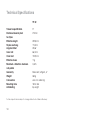
Technische Daten
Tonarm Spezi kation
Montageabstand
Effektive Länge
Überhang
Kröpfungswinkel
Innerer Nulldurchgang
Äusserer Nulldurchgang
Effektive Masse
Maximale Verzerrung zwischen
den Nulldurchgängen
Geometrie
Gewicht
Anschlüsse
Montagebohrung
Antiskating
9“
215mm
232,8mm
17,8mm
23,66°
66,0mm
120,9mm
11g
0,63%
Bearwald / Löfgren „A“
360g
lose Kabel
18mm dia
Gewicht
TP 82
Technische Änderungen vorbehalten. Made in Germany.

12
Notizen

13
Tonearm and Pick-Up Cartridge
The tonearm counterweights are removed for ship-
ping. Screw the large counterweight onto the rear sec-
tion of the tonearm, then the smaller, eccentric weight.
The smaller weight should always sit as close as pos-
sible to the large weight without touching it. Adjust the
tracking force and the azimuth. ➔ Page 14/15
The bias weight is also removed for shipping and
needs to be fi tted to the tonearm. ➔ Page 16
The TP 82 tonearm can accommodate most pick-up
cartridges with a distance of 12.7 mm (½ ”) between the
mounting holes. To connect the pick-up cartridge, push
the four colour-coded cartridge tags onto the cartridge
pins.
If the cartridge pins are not colour-coded, connect them
as follows:
R right channel (signal) ➔ red
G right channel (earth) ➔ green
L left channel (signal) ➔ white
G left channel (earth) ➔ blue
Fig. 1

14
Tracking Force
The tracking force can be adjusted by rotating the to-
nearm counterweights (➔ Fig. 2). The closer the coun-
terweights are to the pick-up cartridge, the higher the
tracking force. The smaller, eccentric weight is used to
adjust the azimuth (➔ Page 15). It should sit as close as
possible to the large weight without touching it.
The correct tracking force can be set with the help of
the stylus gauge. Lower the tonearm lift, move the to-
nearm out over the platter and carefully lower it until the
stylus of the pick-up cartridge comes to rest on the sty-
lus gauge. The stylus guard must be removed for this
procedure.
Great care should be taken to avoid damaging the
stylus.
Note: Refer to the user manual of your pick-up cartridge
to determine the correct tracking force.
Do not move the ring that sits around the middle of
the tonearm tube (➔ Page 13, Fig. 1). It serves as a vi-
bration damper and is effective only at its original
position.
Fig. 2

15
Azimuth
To adjust the azimuth, rotate the smaller, eccentric
counterweight. ➔ Fig. 3
The azimuth setting is correct when the pick-up car-
tridge is exactly perpendicular to the platter surface.
➔ Fig. 4
Fig. 4Fig. 3
90°

16
Anti-Skating Force (Bias)
The interaction of stylus friction and cartridge bearing
forces produces a force which pulls the tonearm to-
wards the centre of the record (referred to as skating
force). This force can be offset with the help of anti-skat-
ing force, which, in the case of the TP 82, is produced
by a bias weight.
Lead the bias weight string through the hanger guide
and hook the string’s loop over the tonearm’s bias shaft
(➔ Fig. 5).
The string can be located in one of six grooves on the
bias shaft. The further out the string loop on the bias
shaft, the higher the anti-skating force. The amount of
anti-skating force required depends on the type of pick-
up cartridge and the tracking force used.
Fig. 5
The amount of anti-skating force required depends
on the type of pick-up cartridge used. If you change
the cartridge for a different type, use a test record
to determine how much anti-skating force is required.

17
Further Tonearm Adjustments
The tonearm headshell allows an overhang adjustment
of ±2.5 mm to be made, which may be necessary when
installing a new pick-up cartridge. To adjust overhang,
loosen the screw holding the headshell and move the
headshell as required. ➔ Fig. 6
Overhang can be further adjusted by +2.5 mm at the
rear of the tonearm. To do so, loosen the screw at the
top of the bearing housing by one or two turns at most
and move the tonearm tube as required. ➔ Fig. 7
The screw at the top of the bearing housing must not
be loosened too far, let alone removed completely,
as this may result in damage to the tonearm!
Take care not to over-tighten the screws after making
adjustments.
Fig. 6
Fig. 7

18
Technical specifi cations subject to change without notice. Made in Germany.
Technical Speci cations
Tonearm speci cation
Distance tonearm pivot
to stylus
Effective length
Stylus overhang
Angular offset
Inner null
Outer null
Effective mass
Maximum distortion between
null-points
Geometry
Weight
Connestors
Mounting hole
Antiskating
9“
215mm
232,8mm
17,8mm
23,66°
66,0mm
120,9mm
11g
0,63%
Bearwald / Löfgren „A“
360g
wires for soldering
18mm dia
by weight
TP 82

19
Notes

Fig. 1
Bras et cellule de lecture
Les contrepoids du bras de lecture sont retirés pour
l’expédition. Vissez le grand contrepoids sur la partie
arrière du bras de lecture, puis le poids excentrique,
plus petit. Le poids le plus petit doit toujours être situé le
plus près possible du grand poids sans toucher celui-
ci. Ajustez la force d’appui et l’azimut. ➔ Page 21/22
Le poids antiskating est aussi retiré pour l’expédition et
doit être monté sur le bras de lecture. ➔ Page 23
La plupart des cellules de lecture ayant un écartement
des trous de fi xation de 12,7 mm (½ ”) peuvent être
montées sur le bras de lecture TP 82. Pour raccorder
la cellule de lecture, placez les quatre cosses repérées
par couleur de la cellule sur les picots de la cellule.
Procédez au raccordement selon le schéma suivant si
la cellule n’a pas de repère couleur :
R Canal droit (signal) ➔ rouge
G Canal droit (masse) ➔ vert
L Canal gauche (signal) ➔ blanc
G Canal gauche (masse) ➔ bleu
20
Seite wird geladen ...
Seite wird geladen ...
Seite wird geladen ...
Seite wird geladen ...
Seite wird geladen ...
Seite wird geladen ...
Seite wird geladen ...
Seite wird geladen ...
-
 1
1
-
 2
2
-
 3
3
-
 4
4
-
 5
5
-
 6
6
-
 7
7
-
 8
8
-
 9
9
-
 10
10
-
 11
11
-
 12
12
-
 13
13
-
 14
14
-
 15
15
-
 16
16
-
 17
17
-
 18
18
-
 19
19
-
 20
20
-
 21
21
-
 22
22
-
 23
23
-
 24
24
-
 25
25
-
 26
26
-
 27
27
-
 28
28


Thorens TP 82 Benutzerhandbuch
- Typ
- Benutzerhandbuch
- Dieses Handbuch eignet sich auch für
in anderen Sprachen
- English: Thorens TP 82 User manual
- français: Thorens TP 82 Manuel utilisateur