Bresser 7902586 Bedienungsanleitung
- Kategorie
- Wetterstationen
- Typ
- Bedienungsanleitung
Dieses Handbuch ist auch geeignet für

Weather Station · Wetterstation ·
WIFI ClearView 7in1
EN Instruction manual
DE Bedienungsanleitung

fi nden.
Visit our website via the following QR Code or web link to fi nd further information on this
product or the available translations of these instructions.
le lien correspondant.
dit product of de beschikbare vertalingen van deze gebruiksaanwijzing.
para ver las versioneAs disponibles.
Desidera ricevere informazioni esaustive su questo prodotto in una lingua specifi ca? Venga
disponibili.
www.bresser.de/P7002586
www.bresser.de/warranty_terms
DE
Besuchen Sie unsere Website über den folgenden QR Code oder Weblink um weitere
Informationen zu diesem Produkt oder die verfügbaren Übersetzungen dieser Anleitung zu
fi nden.
EN
Visit our website via the following QR Code or web link to fi nd further information on this
product or the available translations of these instructions.
FR
Si vous souhaitez obtenir plus d’informations concernant ce produit ou rechercher ce mode
d’emploi en d’autres langues, rendez-vous sur notre site Internet en utilisant le code QR ou
le lien correspondant.
NL
Bezoek onze internetpagina via de volgende QR-code of weblink, voor meer informatie over
dit product of de beschikbare vertalingen van deze gebruiksaanwijzing.
ES
¿Desearía recibir unas instrucciones de uso completas sobre este producto en un idioma
determinado? Entonces visite nuestra página web utilizando el siguiente enlace (código QR)
para ver las versioneAs disponibles.
IT
Desidera ricevere informazioni esaustive su questo prodotto in una lingua specifi ca? Venga
a visitare il nostro sito Web al seguente link (codice QR Code) per conoscere le versioni
disponibili.
www.bresser.de/P7002586
www.bresser.de/warranty_terms
GARANTIE · WARRANTY · GARANTÍA · GARANZIA
Weather Underground is a registered trademark of The Weather Channel, LLC. both in the United States and internationally. The Weather
Underground Logo is a trademark of Weather Underground, LLC. Find out more about Weather Underground at www.wunderground.com
Apple and the Apple logo are trademarks of Apple Inc., registered in the U.S. and other countries. App Store is a service mark of Apple Inc.,
registered in the U.S. and other countries. Google Play and the Google Play logo are trademarks of Google Inc.
WORKS WITH:
RECYCLAGE (TRIMAN/FRANCE)


4 / 60
1 Imprint
Bresser GmbH
Gutenbergstr. 2
46414 Rhede
Germany
www.bresser.de
For any warranty claims or service inquiries, please refer to the information on "Warranty" and "Ser-
vice" in this documentation. We ask for your understanding that unsolicited returns cannot be pro-
cessed.
Errors and technical changes excepted.
© 2023 Bresser GmbH
All rights reserved.
The reproduction of this documentation - even in extracts - in any form (e.g. photocopy, print, etc.) as
well as the use and distribution by means of electronic systems (e.g. image file, website, etc.) without
the prior written permission of the manufacturer is prohibited.
The designations and brand names of the respective companies used in this documentation are gen-
erally protected by trade, trademark and/or patent law in Germany, the European Union and/or other
countries.
2 Validity note
This documentation is valid for the products with the following article numbers:
7002586 7902586
Manual version: 0423
Manual designation:
Manual_7002586-7902586_WIFI-ClearView-7in1_en-de_BRESSER_v042023a
Always provide information when requesting service.
3 About this Instruction Manual
NOTICE
These operating instructions are to be considered a component of the device.
Read the safety instructions and the instruction manual carefully before using this device.
Keep these instruction manual in a safe place for future reference. If the device is sold or passed on,
the instruction manual must be passed on to any subsequent owner/user of the product.
4 General safety instructions
DANGER
Risk of an electric shock!
This device contains electronic parts that are powered by a power source (AC adapter and/or batter-
ies). Improper use of this product may result in electric shock. Electric shock can cause serious or fatal
injuries. It is therefore imperative that you observe the following safety information.

5 / 60
• Never leave children unattended when handling the device! Follow the instructions carefully and
do not attempt to power this device with anything other than power sources recommended in this
instruction manual, otherwise there is a danger of an electric shock!
•Disconnect the power supply by pulling the mains plug when the appliance is not in use, in case of
a longer interruption of operation and before any maintenance and cleaning work.
• Place your device so that it can be disconnected from the power supply at any time. The power
outlet should always be near your appliance and should be easily accessible, as the plug of the
power cord serves as a disconnect device from the mains supply.
• To disconnect the unit from the mains, always pull the mains plug and never pull the cable!
• Check this device, cables and connections for damage before use.
• Never attempt to operate a damaged device, or a device with damaged electrical parts! Damaged
parts must be replaced immediately by an authorized service agent.
• Operate the device only in a completely dry environment and do not touch the device with wet or
damp body parts.
DANGER
Danger of suffocation!
Improper use of this product may result in suffocation, especially for children. It is therefore imperative
that you observe the following safety information.
• Keep packaging materials (plastic bags, rubber bands, etc.) away from children! There is a danger
of choking!
•This product contains small parts that can be swallowed by children! Choking hazard!
DANGER
Explosion hazard!
Improper use of this product may result in fire. It is essential that you observe the following safety in-
formation in order to avoid fires.
• Do not expose the device to high temperatures. Use only the supplied AC adapter or the recom-
mended batteries. Do not short-circuit the device or batteries or dispose of in fire! Excessive heat
and improper handling can cause short circuits, fires and even explosions!
NOTICE
Danger of material damage!
Improper handling may result in damage to the unit and/or accessories. Therefore, use the device only
in accordance with the following safety information.
• Do not disassemble the device! In the event of a defect, please contact your dealer. They will con-
tact the Service Center and can arrange the return of this device for repair if necessary.
• Do not expose the device to high temperatures and protect it from water and high humidity.
• Do not immerse the unit in water!
• Do not subject the device to excessive vibrations.
• Only use accessories and spare parts for this device that comply with the technical specifications.
• Use only the recommended batteries. Always replace weak or empty batteries with a new, com-
plete set of batteries at full capacity. Do not use batteries from different brands or types or with dif-
ferent capacities. Remove batteries from the device if it is not to be used for a longer period of
time!
• Do not use rechargeable batteries (accumulators).

6 / 60
NOTICE
Danger of voltage damage!
The manufacturer accepts no liability for voltage damage as a result of incorrectly inserted batteries,
or the use of an unsuitable mains adapter!
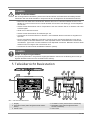
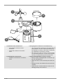
5 Parts overview base station
1
3
45
6
27
8
924
23
22
21
20
19
15 17
11
12 16
13
14 18
10
A
B
25
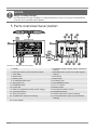
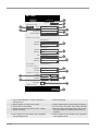
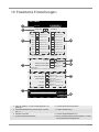
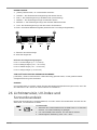
Illustration1: All parts of the base station
1 Display 2 CHANNEL button (outdoor sensor channel se-
lection)
3 HISTORY button (recall recorded measure-
ment data)
4 MAX/MIN button (recall of recorded high/low
values)
5 WIND button 6 SUN button
7 BARO button 8 RAIN button
9 ALARM/SNOOZE button 10 Ventilation slits
11 Stand (fold-out) 12 WIFI/SENSOR button
13 REFRESH button 14 [ °C / °F ] button
15 Power jack 16 RESET button
17 Battery compartment (backup power supply) 18 HI/LO/AUTO selector switch
19 UP/contrast button 20 DOWN/NDX button
21 Wall mount fixture 22 ALERT button (HI/LO alarm settings)
23 ALARM button (alarm time setting) 24 CLOCK SET button (time and user-defined
settings)
25 Power adapter

7 / 60
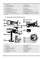
6 Multisensor parts overview
1
2
3
4
5
6
7
8
9
10
11
12
13
14
15
16
D
F
E
C
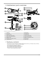
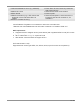
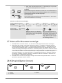
Illustration2: All parts of the multisensor
1 Antenna 2 Rain gauge
3 UV sensor 4 Mounting bar
5 Mounting shoe 6 Circular level
7 Wind cups (wind speed) 8 Thermo-/Hygrometer
9 Wind vane (wind direction) 10 LED function indicator
11 RESET Knob 12 Battery compartment cover
13 Mounting clamp (pipe clamp) 14 Rain sensor
15 Tipping bucket 16 Drain holes
7 Delivery content
Base station (A), power adapter (B), multifunctional outdoor sensor (C), mounting rod (D), mounting
shoe (E), pipe clamp (F), screws, instruction manual
Also required (not included in delivery):
3 x 1.5V batteries type AA/LR6 (outdoor sensor)
Backup battery (not included in delivery):
1 x button cell type CR2032 (Base station)

8 / 60
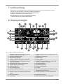
8 Screen display
1
32
30
31
5
4
3
7
68
11
2
10
12
9
13
15
16
17
21
20
18
22
24
25
26
1923
14
27
28
29
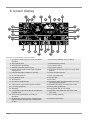
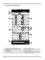
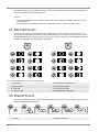
Illustration3: Screen display of the base station
1 Symbol for active high (HI) or low (LO) alarm
(outdoor)
2 Trend arrow (steady, rising or falling)
3 Wind speed value 4 Wind direction (named)
5 Wind direction (graphical) 6 Air pressure value
7 Weather Forecast (12~24 hours) 8 Air pressure alarm
9 Interior sensor channel and signal reception
strength icon
10 Symbol for active high (HI) or low (LO) alarm
(indoor)
11 Internal temperature (station or sensor) 12 Indoor climate indicator
13 Air humidity (indoor) 14 Rain rate (graphical)
15 Precipitation value 16 Sunset time
17 Sunrise time 18 UV value
19 Symbol for enabled alarm 20 Symbol for WIFI connection status and Inter-
net time synchronization
21 Current time or alarm time (hours:minutes) 22 AM/PM information in 12-hour time mode
23 UV index (graphical) 24 Moon phase (graphical)
25 Weekday 26 Date (month-day or vice versa)
27 Temperature value according to the selected
weather index
28 Weather index (feels like, dew point, heat,
wind chill)
29 Wind force (classification according to
Beaufort)
30 Air humidity (outdoor)
31 Multifunction outdoor sensor: Symbol for the
signal reception strength of the multifunction
sensor
32 Outdoor temperature

9 / 60
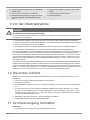
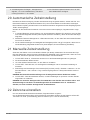
9 Before commissioning
NOTICE
Avoid connection faults!
In order to avoid connection problems between the devices, the following points must be observed
during commissioning.
1. Place the base unit (receiver) and sensor (transmitter) as close together as possible.
2. Connect the power supply to the base unit and wait until the indoor temperature is displayed.
3. Establish power supply for the sensor.
4. Set up/operate the base unit and sensor within the effective transmission range.
5. Make sure that the base unit and the radio sensor are set to the same channel.
When changing the batteries, always remove the batteries from both the base unit and the sensor and
reinsert them in the correct order so that the radio link can be re-established. If one of the two devices
is operated via a mains power connection, the power connection must also be briefly disconnected for
this device when the batteries are changed. If, for example, only the batteries in the sensor are re-
placed, the signal may subsequently not be received at all or not be received correctly.
Note that the actual range depends on the respective construction materials used for the buildings as
well as the respective position of the base unit and the outdoor sensor. External influences (various ra-
dio transmitters and other sources of interference) can greatly reduce the possible range. In such
cases, we recommend finding other locations for both the base unit and the outdoor sensor. Some-
times moving the sensor by just a few centimeters is enough!
10 The first steps
Follow the bullet points in order, to ensure a successful setup.
1. Setting up power supply (base station and wireless sensor)
2. Mount the wireless sensor
3. The base station is now in AP mode (LED flashes green) and ready for initial setup.
4. Create an account with a weather service provider compatible with your station, e.g. wunder-
ground.com or weathercloud.net and add the station to your account ("My Profile" / "Add Weather
station") or ("Devices" / "+ New"). Make a note of the station ID and password, as they will be
needed in the next step.
5. Setting up the base station (Estabish WIFI / Router connection)
6. Viewing weather data via web, mobile or tablet
11 Establish power supply
Base unit
1. Insert the DC plug into the connection socket on the base unit.
2. Insert the Euro plug into the mains power socket.
3. The device is powered on directly.
Installing the backup battery:
1. Remove the battery compartment cover.
2. Insert the battery into the battery compartment. Make sure that the battery terminals are correctly
aligned (+/-).
3. Replace the battery compartment cover.

10 / 60
Wireless sensor
4. Remove the screw on the battery compartment cover with a suitable Phillips screwdriver and re-
move the battery compartment cover.
5. Insert 2 x AA size batteries into the battery compartment. Make sure that the battery terminals are
correctly aligned (+/-).
6. Replace and screw on the battery compartment cover.
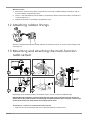
12 Attaching rubber linings
Attach the supplied self-adhesive rubber pads to the clamps as shown to ensure a firmer fitting of the
mounting rod.
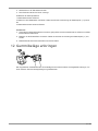
13 Mounting and attaching the multi-function
radio sensor
12
34
5
Depending on the desired location, the wireless sensor can be mounted in different ways.
NOTICE!During installation, always ensure that the upper part of the wind vane is at least 1.5
metres above the ground. Ensure an absolutely horizontal position when using the circular level
in the sensor head. The wind turbine must always point north.
Assembly on a vertical or horizontal wooden element
1. Slide one end of the assembly bar into the aperture below the sensor head.

11 / 60
2. Push a bolt through the hole and put the nut on the other side. Tighten the screw connection hand-
tight.
3. Depending on the desired orientation, slide the opposite end of the assembly bar into the aperture
for vertical or horizontal mounting of the assembly base.
4. Slide another screw through the bore hole of the assembly base and put on the nut on the oppos-
ite site. Tighten the screw connection by hand.
Place the assembly base with its bottom site first on a wooden element. Use 4 wood screws to tighten
it.
Assembly on a vertical or horizontal tube
Repeat steps 1 to 4 as before.
• Place the assembly base with its bottom site first on the tube. Push the tube bracket against the
tube from the opposite site.
• Slide 4 screws through the bore holes of the assemby base and through the bore holes of the tube
bracket on the other site.
• Put on the 4 nuts and tighten the screw connection by hand.
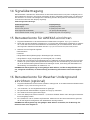
14 Signal transmission
The base station automatically connects to the multi outdoor sensor and (if available) to other wireless
sensors. You can also press the WIFI / SENSOR button to search directly for the sensors. If the con-
nection is successful, the outdoor symbol (OUT) and/or the channel will appear on the display.
Connection status display:
Connection status Display indication
Good signal Receiver symbol
Sensor is searched for Receiver symbol flashes
No signal for 48 hours Er' (Error) is displayed
Sensor battery low, good signal Battery symbol is displayed
15 Setting up user account for AWEKAS
1. Enter the following web address in the address bar of the web browser: https://join.awekas.at
2. Fill in all required information to register with the weather service 'AWEKAS'. Please also read the
detailed additional instructions for your weather station which you can download via the following
weblink: http://archive.bresser.de/download/awekas
3. Make a note of the following:
• Username
• Password
• Geographic latitude in decimal degrees (e.g. 48.30591)
• Geographic longitude in decimal degrees (e.g. 14.2862)
4. After completing the registration with 'AWEKAS', set up the WI-FI connection for your weather sta-
tion (see chapter 'Configuration/Setting up a WI-FI connection') and make the settings described in
the additional instructions for "Setting up the base station to transmit weather data to awekas.at".
NOTICE!For the registration a valid e-mail address, to which you must have access, is mandat-
ory, otherwise the setup and use of the service is not possible!

12 / 60
16 Create a user account for Weather
Underground (optional)
1. Enter the following web address for the 'Weather Underground' service in the address bar of your
web browser: https://www.wunderground.com
2. Click on 'Join' to get to the registration page.
3. Enter your personal user data and click on 'Sign up'.
4. Follow the further setup steps.
5. Under the menu item 'Sensor Network' > 'Connect a Weather Station' your own weather station
can be added.
6. A 'Station ID' and a 'Station Key/Password' are automatically generated by the service, which are
needed for the following configuration of the weather station.
NOTICE!Use a valid e-mail address for registration. Otherwise the service can not be used.
17 Create user account for weathercloud
(optional)
1. Enter the following web address in the address bar of the web browser: https://weathercloud.net
2. Under 'Join us today' enter the personal user data and click on 'Sign up'.
3. After successful registration and verification of the e-mail address, select the menu item "Devices"
under the user account.
4. Click the '+New' link under 'Devices' and enter the device and location data in the 'Create New
Device' window to create a new device. Select the appropriate weather station under 'Model'. For
'Link type' select the option 'Pro Weather Link'.
5. A 'weathercloud ID' and a 'key' which are needed for the following configuration of the weather sta-
tion are automatically generated by the service. These can be reached via the account at weather-
cloud.net under Devices > Settings > Link.
NOTICE!Use a valid e-mail address for registration. Otherwise the service can not be used.
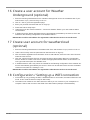
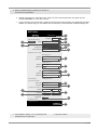
18 Configuration / Setting up a WIFI connection
1. At first start-up or by pressing the WIFI / SENSOR button for 6 seconds, the station switches to AP
mode. In this mode the ward is ready for WIFI setup.
2. The station now creates its own WIFI network to which you can connect to your smartphone or
computer. Search and connect to the SSID of the WIFI station (example: PWS-XXXXXX)

13 / 60
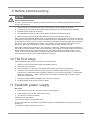
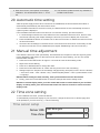
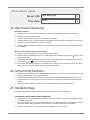
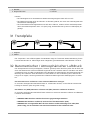
Illustration4:
WIFI connection status:
123
1 Stable: Stable: The base station is connected
to the WIFI router
2 (6-7) will flash. Blinking: The base station is
trying to establish a connection to the WIFI
router
3 (6-7) will flash. Console currently in Access
Point (AP) mode
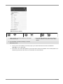
3. Once you are successfully connected, open your Internet browser and enter the address
192.168.1.1 in the URL field.
4. Now enter your router data (SSID of your home WIFI router) and weather service data (station ID /
station key) and select the service for automatic time transmission.

14 / 60
nist.time.gov
Server URL:
0.0000 North*Latitude:
0.0000
Enter 0 to 90, no negative numbers
Enter 0 to 180, no negative numbers
East
*Longitude:
Time server setup
Location for sunrise / sunset
WiFi Router setup
ADVANCED
Wunderground
Station ID: WDw124
******
******
******
IPACIR23Wc
Weather server setup
Station key:
Router:
Add Router
Search
Security type:
Router Password:
WPA2
ROUTER_A
Language: English
Weatherclou d
Station ID:
Station key:
******
IDCR21w1
ws.awekas.at
Station ID:
URL:
Station key:
Mac address 00:0E:C6:00:07:10
Hemisphere
* Depends on the mode l
SETUP
Apply
Firmware version: 1.00
0:00Time Zone:
N
SETTINGS
3
4
15
16
5
2
6
7
8
9
10
11
12
13
14
17
18
1
19
1 Select 'ADVANCED' to enter the advanced
settings menu
2 Select language
3 Select 'Search' to search for routers 4 Select 'Add Router' to add routers manually**
5 Select WIFI router (SSID) 6 If the router is not listed, enter SSID manually
7 Select the security type of the router, usually
WPA2 or WPA3)
8 Enter the WIFI password of the router (leave
the field empty if no password has been as-
signed)
9 Enter 'Station ID' and 'Station Key' registered
with Wunderground*
10 Enter 'Station ID' and 'Station Key' registered
with Weathercloud*

15 / 60
11 Add another weather service (e.g. AWEKAS). 12 Enter 'Station ID' and 'Station Key' registered
with another service*
13 Select time server 14 Select the time zone of your location
15 Enter latitude 16 Enter longitude
17 Select the direction (e.g. for EU countries the
longitude is "East" and for the USA it is
"West")
18 Select the hemisphere in which the sensor is
located (for USA and EU countries "N", for
Australia "S".
19 Press to complete the setting
Leave field blank if registration is not available or entries are to be made later.
**Manual setup requires additional router information (including e.g. IP address, SSID, etc)
WIFI requirements:
5. Supported devices: Intelligent devices (smart devices) with integrated WIFI AP mode (WIFI access
point) and adequate notebooks or PCs.
6. Wi-Fi standard 802.11 b / g / n, supports AP mode
7. Web browser: Internet browser that support HTML 5
Router requirements:
Wi-Fi standard 802.11 b/g/n
Supported router security type WEP, WPA, WPA2, WPA3, open (for routers without password)

16 / 60
19 Advanced settings
Upload
Browse
Firmware version: 1.00
-560~ 560hpa / -16.54 ~ 16.54inHg / -420 ~ 420mmH g
Setting Range:
Temperature oC
Outdoor
Indoor
CH 1
CH 2
CH 3
CH 4
CH 5
CH 6
CH 7
Humidity %
Relative Pressure Offset:
Absolute Pressure Offset:
hpa
Range: -20 ~ 20
(Default: 0.0)
Current offset: 10Current off set: -9
Current offset: -5Current off set: 2
Current offset: -2Current off set: 3
Current offset: -2Current off set: 1.2
Current offset: -5Current off set: -0.2
Current offset: -3Current off set: -20.1
Current offset: -10Current off set: 11.5
Current offset: -3
Current off set: -3
(Default: 0)
Current off set: 10
(Default: 0)
Current off set: 0.2
Current off set: -5Current off set: 1
Pressure
Range: -20.0 ~ 20. 0oC
-36.0 ~ 36.0oF (Default: 0.0)
*UV gain: Range: 0.01 ~ 10(Default: 1.00)
Current gain: 1.1
*Light gain: Range: 0.01 ~ 10(Default: 1.00)
Current gain: 1.1
* Depends on the model
*Wind speed gain:
*Wind direction:
*Rain gain: Range: 0.5 ~ 1.5(Default: 1.00)
Range: -10 ~ 10(Default: 0 o)
Range: 0.5 ~ 1.5(Default: 1.00)
Current gain: 0.8 5
Current off set: 2o
Current gain: 0.7 5
SETUP ADVANCED
SETTINGS
2
36
7
8
9
1
4
5
10
1 Select 'SETUP' to enter the settings menu 2 Select temperature unit
3 Temperature calibration indoor/outdoor and
channel 1-7
4 Pressure calibration section
5 Latest firmware 6 Humidity calibration
7 Select pressure unit 8 Enter an offset value to compensate for the
measured pressure value

17 / 60
9 Gain value for rain, wind speed, UV and light
calibration. The wind direction has a +/- 10 off-
set.
10 The firmware update function only available in
PC/Mac web browser.
20 Automatic time setting
After the power supply and the Wi-Fi connection are established, the time and date information is
automatically transmitted by the Internet time server.
If the time/date information is received correctly, the date and time are set automatically and the re-
ception symbol is displayed.
If the time/date information was not received or not received correctly, proceed as follows:
1. In countries/regions whose time zone differs from the coordinated world time UTC, the time zone
must be set manually (see chapter 'Setting the time zone') in order to display the correct time.
2. Press the REFRESH button on the base unit for about 2 seconds to re-initiate the retrieval of Inter-
net time information.
3. Check the W-LAN settings on the base unit for correctness and correct them if necessary so that
an Internet connection can be established (see chapter 'Establishing a W-LAN connection').
21 Manual time adjustment
If the station is still in AP mode (AP flashes), first deactivate the reception of the time signal by press-
ing the SENSOR / WIFI button for about 8 seconds. When AP stops flashing, you can now set the
time and date manually.
1. Press the CLOCK-SET button for approx. 3 seconds to enter the time setting mode.
2. Digits to be set are flashing.
3. Press UP or DOWN button to change the value.
4. Press the CLOCK-SET button to confirm the entry and move to the next setting.
5. Settings sequence: Sequence of the settings: Daylight saving time (DST) on/off > Hours > Minutes
> 12/24 hour mode > Year > Month > Day > Month-Day/Day-Month > Time synchronization on/off
> Language
NOTICE!When setting the time manually, time synchronization must be deactivated.
6. Finally, press the CLOCK-SET button to save the settings and exit the setting mode.
NOTICE!In normal display mode, press the CLOCK SET button to switch between year and date
display. In setting mode, press the CLOCK SET button for about 2 seconds to return to normal
display mode.
22 Time zone setting
To set a different time zone, proceed as follows:
To automatically set the time display to your time-zone, change the time zone in SETUP page from
'0:00' (default) to your time zone (e g +1:00 for Germany)
nist.time.gov
Server URL:
Time server setup
0:00
Time Zone:

18 / 60
23 Wake-up call setting
Setting the alarm time
1. Press the ALARM button for approx. 2 seconds to enter the alarm time settings mode.
2. Digits to be set are flashing.
3. Press UP or DOWN button to change the value.
4. Press the ALARM button to confirm the entry and move to the next setting.
5. Settings sequence: Hours > minutes
6. Finally, press the ALARM button to save the settings and exit the settings mode.
Switching the alarm clock (and frost warning) on/off
7. Press the ALARM button to display the alarm time.
8. Press the ALARM button again to enable the alarm. The symbol will displayed on the LCD.
9. Press the ALARM button once more to activate the frost warning alarm time. The symbols and
are shown on the display.
10. To deactivate the alarm and frost warning, press the ALARM button until the alarm icons are no
longer displayed.
24 Snooze function
1. When the alarm sound starts, press the ALARM/SNOOZE button to activate the Snooze function.
The Alarm will sound again after 5 minutes.
2. When the alarm sound starts, press the ALARM button or press and hold the ALARM/SNOOZE
button for approx. 3 seconds, to stop the alarm.
3. The alarm will be turned off automatically if no button is pressed within 2 minutes.
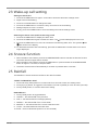
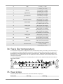
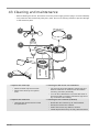
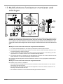
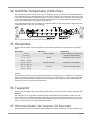
25 Rainfall
The RAINFALL section shows the rainfall or rain rate information.
TO SET THE RAINFALL UNIT
1. Press and hold [ RAIN ] button in normal mode for 2 seconds to enter unit setting mode.
2. Press [Ʌ] or [V] button, to toggle the unit between mm and in (rainfall) or mm/h and in/h (rain rate).
3. Press [ RAIN ] button, to confirm and exit the setting.
RAIN DISPLAY
4. Press [ RAIN ] button to toggle between:
5. HOURLY - the total rainfall in the past hour
6. DAILY - the total rainfall from midnight (default)
7. WEEKLY - the total rainfall of the current week
8. MONTHLY - the total rainfall of the current calendar month
9. TOTAL - the total rainfall since the last reset
10. RATE - Current rainfall rate (base on 10 min rain data)

19 / 60
Level 1 Level 2 Level 3 Level 4
AB
A - Period of rainfall
B - Rain rate level
Rain rate level definition:
Level 1: Light rain (0.1 ~ 2.5 mm/h)
Level 2: Moderate rain (2.51 ~ 10.0 mm/h)
Level 3: Heavy rain (10.1 ~ 50.0 mm/h)
Level 4: Violent rain (> 50.0 mm/h)
TO RESET THE TOTAL RAINFALL RECORD
Press and hold [ HISTORY ] button in Normal mode for 2 seconds to reset all the rainfall record.
NOTE:
To ensure to have correct data, please reset all the rainfall record when you reinstall your wireless 7-
IN-1 sensor to other location.
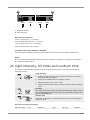
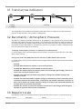
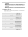
26 Light intensity, UV index and sunburn time
This section shows the light intensity level, UV index and sunburn time. Press the SUN button to
change the mode.
Light intensity
1. During the light intensity mode, press the SUN button for about 3
seconds to enter the setting.
2. Press UP or DOWN button to change the value.
3. Setting sequence: Klux > Kfc > W/m²
4. Finally, press the SUN button to save the settings and exit settings
mode.
UV index
This mode shows the current UV index detected by the outdoor sensor.
The corresponding hazard level and the recommended protection indic-
ator are also displayed.
Sunburn time
This mode is showing the recommend sunburn time that according to
current UV level.
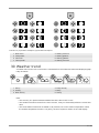
UV index and sunburn schedule
Exposure level Low Moderate High Very high Extreme

20 / 60
UV Index 1 2 3 4 5 6 7 8 9 10 11 12-16
Sunburn time N/A 45 minutes 30 minutes 15 minutes 10 minutes
Recommended
protection indic-
ator
N/A
Moderate or high UV level! It is re-
commended to wear sunglasses, a
broad brim hat and long-sleeved
clothing.
Very high or extreme UV level!
It is recommended to wear
sunglasses, a broad brim hat
and long-sleeved clothing. If
you have to stay outside, make
sure to seek shade.
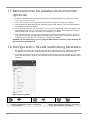
27 Manual measurement display
1. Press the MAX/MIN button several times to display the stored values one after the other.
2. Display sequence: Temperature MAX (outdoor) > Temperature MIN (outdoor) > Humidity MAX
(outdoor) > Humidity MIN (outdoor) > Temperature MAX (indoor) or current channel > Temperat-
ure MIN (indoor) or current channel > Average wind speed MAX > Gust MAX > Feels like MAX >
Feels like MIN > Dew point MAX > Dew point MIN> Heat index MAX > Heat index MIN > Temper-
ature felt (wind chill) MAX > UV Index MAX > Light Intensity MAX > Relative Air Pressure MAX >
Relative Air Pressure MIN > Absolute Air Pressure MAX > Absolute Air Pressure MIN > Rain rate
MAX
3. Press and hold the MAX/MIN button for about 3 seconds during each display to clear the currently
selected value.
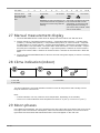
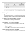
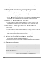
28 Clima indication (indoor)
123
1 too cold 2 comfortable
3 too warm
The clima indication is a pictorial indication based on indoor air temperature and humidity in an at-
tempt to determine comfort level.
Note:
• Comfort indication can vary under the same temperature, depending on the humidity.
• There is no comfort indication when temperature is below 0° C (32° F) or over 60° C (140° F)
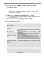
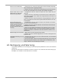
29 Moon phases
In the Northern hemisphere, the moon waxes from the right. Hence the sun-lit area of the moon moves
from right to left in the Northern hemisphere, while in the Southern hemisphere, it moves from left to
right. Below are the 2 tables which illustrate how the moon will appear on the main unit.
Seite laden ...
Seite laden ...
Seite laden ...
Seite laden ...
Seite laden ...
Seite laden ...
Seite laden ...
Seite laden ...
Seite laden ...
Seite laden ...
Seite laden ...
Seite laden ...
Seite laden ...
Seite laden ...
Seite laden ...
Seite laden ...
Seite laden ...
Seite laden ...
Seite laden ...
Seite laden ...
Seite laden ...
Seite laden ...
Seite laden ...
Seite laden ...
Seite laden ...
Seite laden ...
Seite laden ...
Seite laden ...
Seite laden ...
Seite laden ...
Seite laden ...
Seite laden ...
Seite laden ...
Seite laden ...
Seite laden ...
Seite laden ...
Seite laden ...
Seite laden ...
Seite laden ...
Seite laden ...
-
 1
1
-
 2
2
-
 3
3
-
 4
4
-
 5
5
-
 6
6
-
 7
7
-
 8
8
-
 9
9
-
 10
10
-
 11
11
-
 12
12
-
 13
13
-
 14
14
-
 15
15
-
 16
16
-
 17
17
-
 18
18
-
 19
19
-
 20
20
-
 21
21
-
 22
22
-
 23
23
-
 24
24
-
 25
25
-
 26
26
-
 27
27
-
 28
28
-
 29
29
-
 30
30
-
 31
31
-
 32
32
-
 33
33
-
 34
34
-
 35
35
-
 36
36
-
 37
37
-
 38
38
-
 39
39
-
 40
40
-
 41
41
-
 42
42
-
 43
43
-
 44
44
-
 45
45
-
 46
46
-
 47
47
-
 48
48
-
 49
49
-
 50
50
-
 51
51
-
 52
52
-
 53
53
-
 54
54
-
 55
55
-
 56
56
-
 57
57
-
 58
58
-
 59
59
-
 60
60


Bresser 7902586 Bedienungsanleitung
- Kategorie
- Wetterstationen
- Typ
- Bedienungsanleitung
- Dieses Handbuch ist auch geeignet für
in anderen Sprachen
- English: Bresser 7902586 Owner's manual