STIEBEL ELTRON SHU 5 SLi comfort SMALL WATER HEATER Installationsanleitung
- Typ
- Installationsanleitung

BEDIENUNG UND INSTALLATION
OPERATION AND INSTALLATION
UTILISATION ET INSTALLATION
BEDIENING EN INSTALLATIE
OBSLUHA A INSTALACE
KEZELÉS ÉS TELEPÍTÉS
ЭКСПЛУАТАЦИЯ И УСТАНОВКА
Geschlossener (druckfester) Warmwasser-Kleinspeicher | Sealed unvented
(pressurised) small water heaters | Petit chauffe-eau ECS (sous pression) | Gesloten
(drukvaste), kleine warmwaterboiler | Malý tlakový zásobník teplé vody | Kisméretű
zárt (nyomás alatti) elektromos vízmelegítő | Малогабаритный накопительный
водонагреватель закрытого типа (напорный)
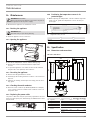
» SHU 5 SLi comfort
» SHU 5 SL GB
» SHU 10 SLi comfort
comfort
82
°C
35
55
65
Eco

2 | SHU 5 | SHU 10 www.stiebel-eltron.com
INHALT | BESONDERE HINWEISE
BESONDERE HINWEISE
- Das Gerät kann von Kindern ab 8 Jahren sowie
von Personen mit verringerten physischen, sen-
sorischen oder mentalen Fähigkeiten oder Man-
gel an Erfahrung und Wissen benutzt werden,
wenn sie beaufsichtigt werden oder bezüglich
des sicheren Gebrauchs des Gerätes unterwiesen
wurden und die daraus resultierenden Gefahren
verstanden haben. Kinder dürfen nicht mit dem
Gerät spielen. Reinigung und Benutzer-Wartung
dürfen nicht von Kindern ohne Beaufsichtigung
durchgeführt werden.
- Bei festem Anschluss an das Stromnetz über eine
Geräteanschlussdose muss das Gerät über eine
Trennstrecke von mindestens 3mm allpolig vom
Netzanschluss getrennt werden können.
- Das Anschlusskabel darf bei Beschädigung oder
Austausch nur durch einen vom Hersteller be-
rechtigten Fachhandwerker mit dem originalen
Ersatzteil ersetzt werden.
- Befestigen Sie das Gerät wie in Kapitel „Installati-
on/ Montage“ beschrieben.
- Beachten Sie den maximal zulässigen Druck
(siehe Kapitel „Installation/ Technische Daten/
Datentabelle“).
- Das Gerät steht unter Druck. Während der Auf-
heizung tropft das Ausdehnungswasser aus dem
Sicherheitsventil.
- Betätigen Sie regelmäßig das Sicherheits-
ventil, um einem Festsitzen z.B. durch Kalk-
ablagerungen vorzubeugen.
- Entleeren Sie das Gerät wie in Kapitel „Installati-
on/ Wartung/ Gerät entleeren“ beschrieben.
- Dimensionieren Sie die Ablaufleitung so, dass bei
voll geöffnetem Sicherheitsventil das Wasser un-
gehindert ablaufen kann.
- Montieren Sie die Ablaufleitung des Sicherheits-
ventils mit einer stetigen Abwärtsneigung in
einem frostfreien Raum.
BESONDERE HINWEISE
BEDIENUNG
1. Allgemeine Hinweise ����������������������������������������3
1.1 Sicherheitshinweise ��������������������������������������������� 3
1.2 Andere Markierungen in dieser Dokumentation ���������� 3
1.3 Maßeinheiten ����������������������������������������������������� 3
2. Sicherheit �����������������������������������������������������3
2.1 Bestimmungsgemäße Verwendung ������������������������� 3
2.2 Sicherheitshinweise ��������������������������������������������� 3
2.3 Prüfzeichen ������������������������������������������������������� 4
3. Gerätebeschreibung �����������������������������������������4
3.1 Bedienung��������������������������������������������������������� 4
4. Reinigung, Pflege und Wartung ����������������������������4
5. Problembehebung �������������������������������������������4
INSTALLATION
6. Sicherheit �����������������������������������������������������5
6.1 Allgemeine Sicherheitshinweise ������������������������������ 5
6.2 Vorschriften, Normen und Bestimmungen ����������������� 5
6.3 Hinweise zur Sicherheitsgruppe ������������������������������ 5
7. Gerätebeschreibung �����������������������������������������5
7.1 Lieferumfang ����������������������������������������������������� 5
7.2 Notwendiges Zubehör ������������������������������������������ 5
8. Vorbereitungen ����������������������������������������������� 5
8.1 Montageort ������������������������������������������������������� 5
9. Montage �������������������������������������������������������6
9.1 Sicherheitsgruppe montieren ��������������������������������� 6
9.2 Montage des Gerätes ������������������������������������������� 6
9.3 Wasseranschluss ������������������������������������������������� 6
9.4 Elektrischer Anschluss ������������������������������������������ 6
10. Inbetriebnahme ����������������������������������������������7
10.1 Erstinbetriebnahme ��������������������������������������������� 7
10.2 Wiederinbetriebnahme ����������������������������������������� 7
11. Einstellungen �������������������������������������������������7
11.1 Temperaturbegrenzung einstellen ��������������������������� 7
12. Außerbetriebnahme �����������������������������������������7
13. Störungsbehebung �������������������������������������������7
13.1 Sicherheitstemperaturbegrenzer aktivieren ��������������� 8
14. Wartung �������������������������������������������������������8
14.1 Gerät entleeren �������������������������������������������������� 8
14.2 Gerät öffnen ������������������������������������������������������ 8
14.3 Gerät entkalken �������������������������������������������������� 8
14.4 Schutzleiter prüfen ���������������������������������������������� 8
14.5 Anschlusskabel austauschen ���������������������������������� 8
14.6 Temperaturfühler im Schutzrohr positionieren ����������� 8
15. Technische Daten ��������������������������������������������� 9
15.1 Maße und Anschlüsse ������������������������������������������ 9
15.2 Elektroschaltplan ������������������������������������������������ 9
15.3 Aufheizdiagramm ����������������������������������������������� 10
15.4 Landesspezifische Zulassungen und Zeugnisse ����������10
15.5 Extreme Betriebs- und Störfallbedingungen �������������� 10
15.6 Angaben zum Energieverbrauch ����������������������������10
15.7 Datentabelle ����������������������������������������������������� 10
GARANTIE
UMWELT UND RECYCLING
MONTAGESCHABLONE SHU 5 SLI | SHU 5 SL GB (IN DER MITTE
DIESER ANLEITUNG)

BEDIENUNG
Allgemeine Hinweise
DEUTSCH
www.stiebel-eltron.com SHU 5 | SHU 10 | 3
- Der Ablauf des Sicherheitsventils muss zur Atmo-
sphäre geöffnet bleiben.
BEDIENUNG
1. Allgemeine Hinweise
Die Kapitel „Besondere Hinweise“ und „Bedienung“ richten sich
an den Gerätebenutzer und den Fachhandwerker.
Das Kapitel „Installation“ richtet sich an den Fachhandwerker.
Hinweis
Lesen Sie diese Anleitung vor dem Gebrauch sorgfältig
durch und bewahren Sie sie auf.
Geben Sie die Anleitung ggf. an einen nachfolgenden
Benutzer weiter.
1.1 Sicherheitshinweise
1.1.1 Aufbau von Sicherheitshinweisen
! SIGNALWORT Art der Gefahr
Hier stehen mögliche Folgen bei Nichtbeachtung des Si-
cherheitshinweises.
Hier stehen Maßnahmen zur Abwehr der Gefahr.
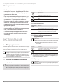
1.1.2 Symbole, Art der Gefahr
Symbol Art der Gefahr
Verletzung
Stromschlag
Verbrennung
(Verbrennung, Verbrühung)
1.1.3 Signalworte
SIGNALWORT Bedeutung
GEFAHR Hinweise, deren Nichtbeachtung schwere Verletzungen
oder Tod zur Folge haben.
WARNUNG Hinweise, deren Nichtbeachtung schwere Verletzungen
oder Tod zur Folge haben kann.
VORSICHT Hinweise, deren Nichtbeachtung zu mittelschweren oder
leichten Verletzungen führen kann.
1.2 Andere Markierungen in dieser Dokumentation
Hinweis
Allgemeine Hinweise werden mit dem nebenstehenden
Symbol gekennzeichnet.
Lesen Sie die Hinweistexte sorgfältig durch.
Symbol Bedeutung
Sachschaden
(Geräte-, Folge-, Umweltschaden)
Geräteentsorgung
Dieses Symbol zeigt Ihnen, dass Sie etwas tun müssen.
Die erforderlichen Handlungen werden Schritt für Schritt
beschrieben.
1.3 Maßeinheiten
Hinweis
Wenn nicht anders angegeben, sind alle Maße in Milli-
meter.
2. Sicherheit
2.1 Bestimmungsgemäße Verwendung
Das geschlossene (druckfeste) Gerät ist für die Erwärmung von
Trinkwasser bestimmt. Mit dem Gerät können Sie eine oder meh-
rere Entnahmestellen versorgen.
Das Gerät ist für den Einsatz im häuslichen Umfeld vorgesehen.
Es kann von nicht eingewiesenen Personen sicher bedient wer-
den. In nicht häuslicher Umgebung, z.B. im Kleingewerbe, kann
das Gerät ebenfalls verwendet werden, sofern die Benutzung in
gleicher Weise erfolgt.
Eine andere oder darüber hinausgehende Benutzung gilt als nicht
bestimmungsgemäß. Zum bestimmungsgemäßen Gebrauch ge-
hört auch das Beachten dieser Anleitung sowie der Anleitungen
für eingesetztes Zubehör.
2.2 Sicherheitshinweise
WARNUNG Verbrennung
Die Armatur kann während des Betriebs eine Temperatur
von über 60°C annehmen.
Bei Auslauftemperaturen größer 43°C besteht Verbrü-
hungsgefahr.
! WARNUNG Verletzung
Der Temperatur-Einstellknopf darf nur durch einen Fach-
handwerker abgezogen werden.
! WARNUNG Verletzung
Das Gerät kann von Kindern ab 8 Jahren sowie von Per-
sonen mit verringerten physischen, sensorischen oder
mentalen Fähigkeiten oder Mangel an Erfahrung und
Wissen benutzt werden, wenn sie beaufsichtigt werden
oder bezüglich des sicheren Gebrauchs des Gerätes un-
terwiesen wurden und die daraus resultierenden Gefah-
ren verstanden haben. Kinder dürfen nicht mit dem Gerät
spielen. Reinigung und Benutzer-Wartung dürfen nicht
von Kindern ohne Beaufsichtigung durchgeführt werden.
Falls Kinder oder Personen mit eingeschränkten körperlichen, sen-
sorischen oder geistigen Fähigkeiten das Gerät benutzen, empfeh-
!
!

BEDIENUNG
Gerätebeschreibung
4 | SHU 5 | SHU 10 www.stiebel-eltron.com
len wir eine dauerhafte Temperaturbegrenzung. Die Begrenzung
kann der Fachhandwerker einstellen.
! Sachschaden
Wenn die Ablaufleitung des Sicherheitsventils verschlos-
sen wird, kann das Ausdehnungswasser zu einem Was-
serschaden führen.
Verschließen Sie nicht die Ablaufleitung.
! Sachschaden
Das Gerät und die Armatur sind vom Nutzer vor Frost zu
schützen.
2.3 Prüfzeichen
Siehe Typenschild am Gerät.
3. Gerätebeschreibung
Das geschlossene (druckfeste) Gerät hält ständig den Wasserin-
halt mit der vorgewählten Temperatur bereit. Das Gerät schaltet
sich automatisch ein, sobald die Temperatur im Gerät unter den
eingestellten Wert sinkt.
Je nach Jahreszeit ergeben sich bei verschiedenen Kaltwasser-
temperaturen unterschiedliche maximale Mischwasser- und Aus-
laufmengen.
Hinweis
Der Fachhandwerker kann eine Temperaturbegrenzung
am Gerät vornehmen (siehe „Installation/ Einstellungen/
Temperaturbegrenzung einstellen“).
Hinweis
Das Gerät steht unter Wasserleitungsdruck. Wenn sich der
Speicher aufheizt, vergrößert sich das Wasservolumen.
Dabei tropft das Ausdehnungswasser durch das Sicher-
heitsventil ab. Dies ist ein notwendiger und normaler
Vorgang.
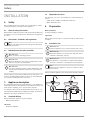
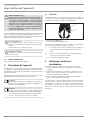
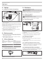
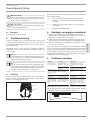
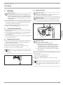
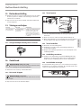
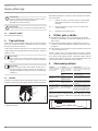
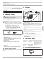
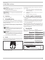
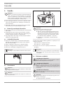
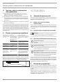
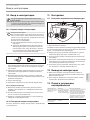
3.1 Bedienung
Die gewünschte Warmwasser-Auslauftemperatur können Sie am
Temperatur-Einstellknopf stufenlos einstellen. Während des Auf-
heizvorgangs leuchtet die Aufheizanzeige.
D0000047406
1
2
1 Aufheizanzeige
2 Temperatur-Einstellknopf
Systembedingt können die Temperaturen vom Sollwert abwei-
chen.
°C = kalt. Bei dieser Einstellung ist das Gerät vor Frost ge-
schützt. Die Armatur und die Wasserleitung sind nicht
geschützt.
Eco = empfohlene Energiesparstellung (ca. 60°C), geringe
Wassersteinbildung
82 = maximal einstellbare Temperatur
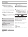
4. Reinigung, Pflege und Wartung
Verwenden Sie keine scheuernden oder anlösenden Reini-
gungsmittel. Zur Pflege und Reinigung des Gerätes genügt
ein feuchtes Tuch.
Kontrollieren Sie regelmäßig die Armaturen. Kalk an den
Armaturausläufen können Sie mit handelsüblichen Entkal-
kungsmitteln entfernen.
Lassen Sie die Funktion der Sicherheitsgruppe regelmäßig
von einem Fachhandwerker prüfen.
Fast jedes Wasser scheidet bei hohen Temperaturen Kalk aus.
Dieser setzt sich im Gerät ab und beeinflusst die Funktion und
Lebensdauer des Gerätes. Die Heizkörper sollten deshalb bei Be-
darf entkalkt werden. Der Fachhandwerker, der die örtliche Was-
serqualität kennt, nennt Ihnen den Zeitpunkt für eine Entkalkung.
5. Problembehebung
Störung Ursache Behebung
Das Gerät liefert kein
warmes Wasser.
Der Temperatur-Ein-
stellknopf ist auf „°C“
gestellt.
Schalten Sie das Gerät durch
Drehen des Temperatur-Ein-
stellknopfes ein.
Am Gerät liegt keine
Spannung an.
Prüfen Sie den Stecker/ die
Sicherungen in der Hausinstal-
lation.
Wasser kann nur mit
einer verminderten
Zapfmenge gezapft
werden.
Der Strahlregler in der
Armatur ist verkalkt.
Entkalken / erneuern Sie den
Strahlregler.
Starke Siedegeräu-
sche im Gerät.
Das Gerät ist verkalkt. Lassen Sie das Gerät vom Fach-
handwerker entkalken.
Wasser tropft nach
dem Aufheizen aus
dem Sicherheitsven-
til der Sicherheits-
gruppe.
Das Sicherheitsventil
ist verkalkt oder ver-
schmutzt.
Schalten Sie das Gerät aus.
Schalten Sie das Gerät drucklos,
indem Sie das Gerät von der
Spannungsversorgung und der
Wasserzufuhr trennen. Lassen
Sie das Sicherheitsventil vom
Fachhandwerker prüfen.
Können Sie die Ursache nicht beheben, rufen Sie den Fachhand-
werker. Zur besseren und schnelleren Hilfe teilen Sie ihm die
Nummer vom Typenschild mit (000000-0000-000000).
Typ:
Nr.: ...... - .... - ......
D0000047804
SHU...

DEUTSCH
www.stiebel-eltron.com SHU 5 | SHU 10 | 5
INSTALLATION
Sicherheit
INSTALLATION
6. Sicherheit
Die Installation, Inbetriebnahme sowie Wartung und Reparatur
des Gerätes darf nur von einem Fachhandwerker durchgeführt
werden.
6.1 Allgemeine Sicherheitshinweise
Wir gewährleisten eine einwandfreie Funktion und Betriebssicher-
heit nur, wenn das für das Gerät bestimmte Original-Zubehör und
die originalen Ersatzteile verwendet werden.
6.2 Vorschriften, Normen und Bestimmungen
Hinweis
Beachten Sie alle nationalen und regionalen Vorschriften
und Bestimmungen.
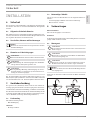
6.3 Hinweise zur Sicherheitsgruppe
! Sachschaden
Der Betriebsüberdruck darf nicht überschritten werden.
! Sachschaden
Die Ablaufleitung der Sicherheitsgruppe muss mit Gefälle
verlegt und zur Atmosphäre geöffnet sein.
! Sachschaden
Eine regelmäßige Wartung und Betätigung der Sicher-
heitseinrichtung ist erforderlich (siehe Installationsan-
leitung der Sicherheitsgruppe).
Bei der Verwendung eines Kunststoff-Geruchverschlusses (z.B.
DN40 für die Spüle) entfällt das Tauchrohr der SVMT. Verbinden
Sie den Überlauftrichter z.B. mit dem Spülmaschinenanschluss.
7. Gerätebeschreibung
Das geschlossene (druckfeste) Gerät ist nur für eine Untertisch-
montage geeignet. Das Gerät ist zur Versorgung einer oder mehre-
rer Entnahmestellen für die Erwärmung von Kaltwasser bestimmt.
Das Gerät darf nur mit Druckarmaturen und in Verbindung mit der
Sicherheitsgruppe SVMT installiert werden (siehe Kapitel „Instal-
lation/ Gerätebeschreibung/ Notwendiges Zubehör“).
7.1 Lieferumfang
Mit dem Gerät wird geliefert:
- Wandaufhängung
SHU 10 SLi
- Montageschablone
7.2 Notwendiges Zubehör
Für die geschlossene Betriebsweise ist das folgende Zubehör er-
hältlich:
- Sicherheitsgruppe SVMT für eine Untertischmontage
- Wasserverteiler T-Stücke
8. Vorbereitungen
Wasserinstallation
Eine Sicherheitsgruppe ist erforderlich.
Armaturen
Es dürfen nur Druckarmaturen in Verbindung mit der Sicherheits-
gruppe SVMT installiert werden.
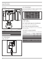
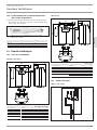
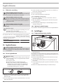
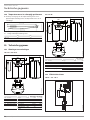
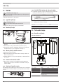
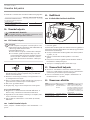
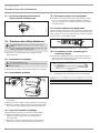
8.1 Montageort
! Sachschaden
Die Installation des Gerätes darf nur in einem frostfreien
Raum erfolgen.
! Sachschaden
Montieren Sie das Gerät an die Wand. Die Wand muss
ausreichend tragfähig sein.
! Sachschaden
Das Gerät ist nur für eine Untertischmontage geeignet.
Die Wasseranschlüsse des Gerätes zeigen nach oben.
Hinweis
Achten Sie darauf, dass das Gerät für Wartungsarbeiten
frei zugänglich ist.
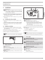
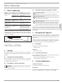
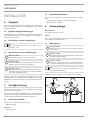
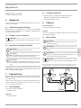
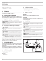
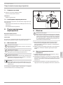
Montieren Sie das Gerät senkrecht und in der Nähe der Entnah-
mestelle.
82
°C
35
55
65
Eco
65
400-450
500
100-200
26�02�06�0206

6 | SHU 5 | SHU 10 www.stiebel-eltron.com
INSTALLATION
Montage
9. Montage
! Sachschaden
Beachten Sie beim Einsatz von Kunststoff-Rohrsystemen
die extremen Betriebs- und Störfallbedingungen, die
am Gerät auftreten können (siehe Kapitel „Installation/
Technische Daten/ Extreme Betriebs- und Störfallbedin-
gungen“).
Um zwei Waschtische zu versorgen, verwenden Sie die „Was-
serverteiler T-Stücke“ (siehe Kapitel „Installation/ Gerätebe-
schreibung/ Notwendiges Zubehör“).
Verlegen Sie die Verbindungen zur zweiten Armatur bauseits
zum Beispiel in 10mm Kupferrohr.
9.1 Sicherheitsgruppe montieren
Montieren Sie die Sicherheitsgruppe in der Kaltwasser-Zulei-
tung des Gerätes.
Beachten Sie die Hinweise zur Sicherheitsgruppe
(siehe Kapitel „Installation/ Sicherheit/ Hinweise zur
Sicherheitsgruppe“).
Berücksichtigen Sie die Hinweise in der Installationsanwei-
sung der Sicherheitsgruppe.
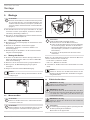
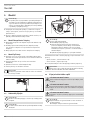
9.2 Montage des Gerätes
Zeichnen Sie die Bohrlöcher mit der Montageschablone an
(SHU 10 SLi beiliegend oder SHU5SLi | SHU5SLGB im Mit-
telteil dieser Anleitung).
Bohren Sie die Löcher und setzen Sie geeignete Dübel ein.
Befestigen Sie die Wandaufhängung mit geeigneten
Schrauben.
Hängen Sie das Gerät auf die Wandaufhängung.
Hinweis
Sie können das überschüssige Anschlusskabel in das Ka-
beldepot legen.
26�02�06�0201
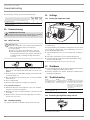
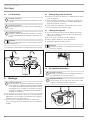
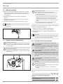
9.3 Wasseranschluss
! Sachschaden
Führen Sie alle Wasseranschluss- und Installationsarbei-
ten nach Vorschrift aus.
! Sachschaden
Beim Festdrehen der Verschraubungen müssen Sie mit
einem geeigneten Schraubenschlüssel gegenhalten.
85
°C
35
55
65
Eco
comfor t
D0000034825
14 19
! Sachschaden
Das Gerät kann funktionsunfähig werden.
Vertauschen Sie nicht die Wasseranschlüsse.
Stellen Sie die Durchflussmenge ein (siehe Anleitung
der Sicherheitsgruppe). Beachten Sie die maximal
zulässige Durchflussmenge bei voll geöffneter Arma-
tur (siehe Kapitel „Installation/ Technische Daten/
Datentabelle“).
Schließen Sie die hydraulischen Anschlüsse flach-
dichtend an.
Ordnen Sie die Farbkennzeichnung der Armaturen-Wasseran-
schlüsse und des Gerätes einander zu:
- Rechts blau = „Kaltwasser Zulauf“
- Links rot = „Warmwasser Auslauf“
Schrauben Sie die Wasseranschlüsse der Armatur fest an das
Gerät.
Hinweis
Achten Sie darauf, dass die Wasseranschlüsse bei der
Montage nicht geknickt werden. Vermeiden Sie Zugspan-
nung beim Einbau.
9.4 Elektrischer Anschluss
WARNUNG Stromschlag
Führen Sie alle elektrischen Anschluss- und Installations-
arbeiten nach Vorschrift aus.
WARNUNG Stromschlag
Bei festem Anschluss an das Stromnetz über eine Gerä-
teanschlussdose muss das Gerät über eine Trennstrecke
von mindestens 3mm allpolig vom Netzanschluss ge-
trennt werden können.
WARNUNG Stromschlag
Achten Sie darauf, dass das Gerät an den Schutzleiter
angeschlossen ist.
! Sachschaden
Die auf dem Typenschild angegebene Spannung muss mit
der Netzspannung übereinstimmen.
Beachten Sie das Typenschild.

DEUTSCH
www.stiebel-eltron.com SHU 5 | SHU 10 | 7
INSTALLATION
Inbetriebnahme
Folgende elektrische Anschlussmöglichkeiten sind zulässig:
SHU 5 SLi SHU 5 SL GB SHU 10 SLi
Anschluss an eine frei zugängliche
Schutzkontaktsteckdose mit ent-
sprechendem Stecker
X
-
X
Festanschluss an eine Gerätean-
schlussdose mit Schutzleiter
X X X
10. Inbetriebnahme
WARNUNG Stromschlag
Die Inbetriebnahme darf nur durch einen Fachhandwer-
ker unter Beachtung der Sicherheitsvorschriften erfolgen.
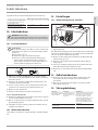
10.1 Erstinbetriebnahme
! Sachschaden
Wenn die Reihenfolge (erst Wasser, dann Strom) nicht
eingehalten wird, spricht der Sicherheitstemperaturbe-
grenzer an.
Gehen Sie wie folgt vor:
Erneuern Sie ggf. den Temperaturregler.
Machen Sie den Sicherheitstemperaturbegrenzer
durch Drücken des Rückstellknopfes einsatzbereit
(siehe Kapitel „Installation/ Störungsbehebung/ Si-
cherheitstemperaturbegrenzer aktivieren“).
1. 2.
D0000049325
Öffnen Sie entweder das Warmwasser-Ventil der Armatur
oder stellen Sie den Einhandmischer auf „warm“, bis Wasser
blasenfrei austritt.
Prüfen Sie die Sicherheitsgruppe. Beim Anlüften muss der
volle Wasserstrahl herauslaufen.
Stecken Sie den Stecker in die Schutzkontaktsteckdose oder
schalten Sie die Sicherung in der Hausinstallation ein.
Wählen Sie eine Temperatur.
Prüfen Sie die Dichtheit aller Wasserinstallationen.
10.1.1 Übergabe des Gerätes
Erklären Sie dem Benutzer die Funktion des Gerätes. Machen
Sie ihn mit dem Gebrauch vertraut.
Weisen Sie den Benutzer auf mögliche Gefahren hin, speziell
die Verbrühungsgefahr.
Übergeben Sie diese Anleitung und falls vorhanden die An-
leitungen vom Zubehör.
10.2 Wiederinbetriebnahme
Siehe Kapitel „Installation/ Inbetriebnahme/ Erstinbetriebnah-
me“.
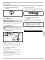
11. Einstellungen
11.1 Temperaturbegrenzung einstellen
85
°C
35
55
65
Eco
comfor t
26�02�06�0007
1 2
1 Temperatur-Einstellknopf
2 Begrenzungsring
Mit dem Begrenzungsring unter dem Temperatur-Einstellknopf
können Sie den Einstellbereich des Temperatur-Einstellknopfes
auf eine maximale Temperatur begrenzen.
Drehen Sie den Temperatur-Einstellknopf in Nullstellung (bis
Linksanschlag auf „°C“).
Ziehen Sie den Temperatur-Einstellknopf und den Begren-
zungsring ab.
Setzen Sie den Begrenzungsring mit der gewünschten maxi-
malen Einstellung auf die Reglerachse auf.
Montieren Sie den Temperatur-Einstellknopf in Nullstellung
(°C).
12. Außerbetriebnahme
Trennen Sie das Gerät vom Stromnetz, indem Sie den Ste-
cker ziehen oder die Sicherung in der Hausinstallation
ausschalten.
Entleeren Sie das Gerät (siehe Kapitel „Installation/ War-
tung/ Gerät entleeren“).
13. Störungsbehebung
Störung Ursache Behebung
Das Gerät liefert kein
warmes Wasser.
Der Sicherheitstem-
peraturbegrenzer hat
ausgelöst.
Beheben Sie die Fehlerursache.
Erneuern Sie ggf. den Tempe-
raturregler. Machen Sie den
Sicherheitstemperaturbegrenzer
wieder einsatzbereit, indem
Sie den Rückstellknopf am Si-
cherheitstemperaturbegrenzer
eindrücken.
Starke Siedegeräu-
sche im Gerät.
Das Gerät ist verkalkt. Entkalken Sie das Gerät.

8 | SHU 5 | SHU 10 www.stiebel-eltron.com
INSTALLATION
Wartung
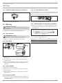
13.1 Sicherheitstemperaturbegrenzer aktivieren
26�02�06�0171
Drücken Sie den Rückstellknopf ein.
14. Wartung
WARNUNG Stromschlag
Trennen Sie bei allen Arbeiten das Gerät allpolig vom
Stromnetz.
Demontieren Sie das Gerät bei Wartungsarbeiten.
14.1 Gerät entleeren
WARNUNG Verbrennung
Beim Entleeren kann heißes Wasser austreten.
Entleeren Sie das Gerät über die Anschlussstutzen.
14.2 Gerät öffnen
85
°C
35
55
65
Eco
comfort
26�02�06�0202
Ziehen Sie den Temperatur-Einstellknopf und den Begren-
zungsring ab.
Schrauben Sie die Schrauben unter dem Temperatur-Ein-
stellknopf heraus.
Öffnen Sie die Gerätekappe, indem Sie die Riegelschrauben
nach innen absenken und die Kappe aufschwenken und
abnehmen.
14.3 Gerät entkalken
Demontieren Sie den Heizflansch.
Entfernen Sie durch vorsichtiges Klopfen den groben Kalk
vom Heizkörper.
Tauchen Sie den Heizkörper bis zur Flanschplatte in Entkal-
kungsmittel ein.
14.4 Schutzleiter prüfen
Prüfen Sie den Schutzleiter (in Deutschland z.B. DGUV3) an
einem Wasseranschlussstutzen und am Schutzleiterkontakt
des Anschlusskabels.
14.5 Anschlusskabel austauschen
Das Anschlusskabel darf nur von einem Fachhandwerker mit dem
originalen Ersatzteil ersetzt werden. Alternativ können Sie die
elektrische Leitung H05VV-F3x1,0 verwenden.
26�02�06�0205
Legen Sie das Anschlusskabel in die Führung.
14.6 Temperaturfühler im Schutzrohr positionieren
Führen Sie beim Austausch des Temperaturreglers und des
Sicherheitstemperaturbegrenzers die Temperaturfühler in
das Schutzrohr.
L2
L1
26�02�01�0370
L1 Temperaturregler
L2 Sicherheitstemperaturbegrenzer
L1 L2
SHU 5 SLi 170 180
SHU 5 SL GB 170 180
SHU 10 SLi 160 180

DEUTSCH
www.stiebel-eltron.com SHU 5 | SHU 10 | 9
INSTALLATION
Technische Daten
15. Technische Daten
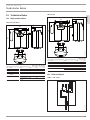
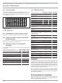
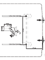
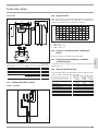
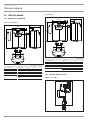
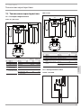
15.1 Maße und Anschlüsse
SHU 5 SLi | SHU 10 SLi
c06 c01
100
a10
70
a30
a20
i13
14
D0000024351
SHU 5 SLi SHU 10 SLi
a10 Gerät Höhe mm 421 503
a20 Gerät Breite mm 263 295
a30 Gerät Tiefe mm 230 275
c01 Kaltwasser Zulauf Außengewinde G 3/8 A G 3/8 A
c06 Warmwasser
Auslauf
Außengewinde G 3/8 A G 3/8 A
i13 Wandaufhängung Höhe mm 328 363
Lochabstand hori-
zontal
mm 140 200
SHU 5 SL GB
c06 c01
100
a10
70
a30
a20
i13
14
D0000047346
SHU 5 SL GB
a10 Gerät Höhe mm 421
a20 Gerät Breite mm 263
a30 Gerät Tiefe mm 230
c01 Kaltwasser Zulauf Außengewinde G 3/8 A
c06 Warmwasser Auslauf Außengewinde G 3/8 A
i13 Wandaufhängung Höhe mm 328
Lochabstand horizontal mm 140
15.2 Elektroschaltplan
1/N/PE ~ 220 - 240V
ϑ>
ϑ>
L N
D0000047076

10 | SHU 5 | SHU 10 www.stiebel-eltron.com
INSTALLATION | GARANTIE | UMWELT UND RECYCLING
Technische Daten
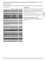
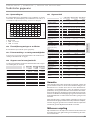
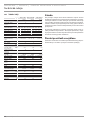
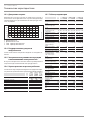
15.3 Aufheizdiagramm
Die Aufheizdauer ist abhängig von der Verkalkung und der Rest-
wärme. Die Aufheizzeit bei einem Kaltwasserzulauf mit 10°C und
maximaler Temperatureinstellung entnehmen Sie dem Diagramm.
35 40 45 50 55 60 65 70 75 80 85
0
5
10
15
20
25
30
1
2
84�02�02�0044
x Temperatur in °C
y Dauer in min
1 2kW 10l-Gerät
2 2kW 5l-Gerät
15.4 Landesspezifische Zulassungen und Zeugnisse
Die Prüfzeichen sind auf dem Typenschild ersichtlich.
15.5 Extreme Betriebs- und Störfallbedingungen
Im Störfall kann in der Installation kurzzeitig eine Temperatur von
maximal 105 °C auftreten.
15.6 Angaben zum Energieverbrauch
Produktdatenblatt: Konventionelle Warmwasserbereiter nach
Verordnung (EU) Nr. 812/2013 und 814/2013
SHU 5 SLi SHU 5 SL
GB
SHU 10 SLi
222151 222153 222187
Hersteller STIEBEL
ELTRON
STIEBEL
ELTRON
STIEBEL
ELTRON
Lastprofil XXS XXS XXS
Energieeffizienzklasse A A A
Energetischer Wirkungsgrad %37 37 36
Jährlicher Stromverbrauch kWh 497 497 507
Temperatureinstellung ab
Werk
°C 55 55 55
Schallleistungspegel dB(A) 15 15 15
Täglicher Stromverbrauch kWh 2,313 2,313 2.370
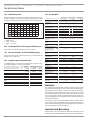
15.7 Datentabelle
SHU 5 SLi SHU 5 SL GB SHU 10 SLi
222151 222153 222187
Hydraulische Daten
Nenninhalt l 5 5 10
Mischwassermenge
40 °C
l 10 10 19
Elektrische Daten
Nennspannung V220 230 240 220 230 240 220 230 240
Nennleistung kW 1,8 2,0 2,2 1,8 2,0 2,2 1,8 2,0 2,2
Nennstrom A8,3 8,7 9,1 8,3 8,7 9,1 8,3 8,7 9,1
Absicherung A 10 10 10 10 10 10 10 10 10
Phasen 1/N/PE 1/N/PE 1/N/PE
Frequenz Hz 50/60 50/60 50/60
Einsatzgrenzen
Temperatureinstell-
bereich
°C ca. 35 - 82 ca. 35 - 82 ca. 35 - 82
Max. zulässiger
Druck
MPa 0,7 0,7 0,7
Max. Durchfluss-
menge
l/
min
5 5 10
Energetische Daten
Bereitschaftsener-
gieverbrauch/24 h
bei 65 °C
kWh
0,29
0,29
0,36
Energieeffizienz-
klasse
A A A
Ausführungen
Schutzart (IP) IP24 D IP24 D IP24 D
Montageart Untertisch Untertisch Untertisch
Bauart geschlossen geschlossen geschlossen
Innenbehälter Werk-
stoff
Kupfer Kupfer Kupfer
Werkstoff Wärme-
dämmung
EPS EPS EPS
Gehäusematerial PS PS PS
Farbe weiß weiß weiß
Anschlüsse
Wasseranschluss G 3/8 A G 3/8 A G 3/8 A
Dimensionen
Tiefe mm 230 230 275
Höhe mm 421 421 503
Breite mm 263 263 295
Gewichte
Gewicht kg 5,2 5,2 7,6
Garantie
Für außerhalb Deutschlands erworbene Geräte gelten nicht
die Garantiebedingungen unserer deutschen Gesellschaften.
Vielmehr kann in Ländern, in denen eine unserer Tochterge-
sellschaften unsere Produkte vertreibt, eine Garantie nur von
dieser Tochtergesellschaft erteilt werden. Eine solche Garantie
ist nur dann erteilt, wenn die Tochtergesellschaft eigene Ga-
rantiebedingungen herausgegeben hat. Darüber hinaus wird
keine Garantie erteilt.
Für Geräte, die in Ländern erworben werden, in denen keine
unserer Tochtergesellschaften unsere Produkte vertreibt, er-
teilen wir keine Garantie. Etwaige vom Importeur zugesicherte
Garantien bleiben hiervon unberührt.
Umwelt und Recycling
Bitte helfen Sie, unsere Umwelt zu schützen. Entsorgen Sie die
Materialien nach der Nutzung gemäß nationalen Vorschriften.

www.stiebel-eltron.com SHU 5 | SHU 10 | 11
ENGLISH
CONTENTS | SPECIAL INFORMATION
SPECIAL INFORMATION
- The appliance may be used by children aged 8
and older and persons with reduced physical,
sensory or mental capabilities or a lack of ex-
perience and know-how, provided that they are
supervised or they have been instructed on how
to use the appliance safely and have understood
the resulting risks. Children must never play with
the appliance. Children must never clean the ap-
pliance or perform user maintenance unless they
are supervised.
- In the case of permanent connection to the power
supply via a junction box, ensure that the appli-
ance can be isolated from the mains by an isola-
tor that disconnects all poles with at least 3mm
contact separation.
- The power cable may only be replaced (for exam-
ple if damaged) by a qualified contractor author-
ised by the manufacturer, using an original spare
part.
- Secure the appliance as described in chapter "In-
stallation/ Installation".
- Observe the maximum permissible pressure (see
chapter "Installation/ Specification/ Data table").
- The appliance is pressurised. During the heat-up
process, expansion water will drip from the safety
valve.
- Regularly activate the safety valve to prevent
it from becoming blocked, e.g. by limescale
deposits.
- Drain the appliance as described in chapter "In-
stallation/ Maintenance/ Draining the appliance".
- Size the drain pipe so that water can drain off un-
impeded when the safety valve is fully opened.
- Fit the drain pipe of the safety valve with a con-
stant downward slope and in a room free from
the risk of frost.
- The safety valve drain must remain open to the
atmosphere.
SPECIAL INFORMATION
OPERATION
1. General information ��������������������������������������� 12
1.1 Safety instructions ����������������������������������������������12
1.2 Other symbols in this documentation ���������������������� 12
1.3 Units of measurement �����������������������������������������12
2. Safety �������������������������������������������������������� 12
2.1 Intended use �����������������������������������������������������12
2.2 Safety instructions ����������������������������������������������12
2.3 Test symbols �����������������������������������������������������13
3. Appliance description ������������������������������������� 13
3.1 Operation ��������������������������������������������������������� 13
4. Cleaning, care and maintenance ������������������������� 13
5. Troubleshooting �������������������������������������������� 13
INSTALLATION
6. Safety �������������������������������������������������������� 14
6.1 General safety instructions ����������������������������������� 14
6.2 Instructions, standards and regulations ������������������� 14
6.3 Information on the safety assembly ������������������������ 14
7. Appliance description ������������������������������������� 14
7.1 Standard delivery ����������������������������������������������� 14
7.2 Required accessories ������������������������������������������ 14
8. Preparation ������������������������������������������������� 14
8.1 Installation site �������������������������������������������������� 14
9. Installation �������������������������������������������������� 15
9.1 Installing the safety assembly �������������������������������� 15
9.2 Appliance installation ������������������������������������������ 15
9.3 Water connection ����������������������������������������������� 15
9.4 Power supply ����������������������������������������������������15
10. Commissioning ��������������������������������������������� 16
10.1 Initial start-up ��������������������������������������������������� 16
10.2 Recommissioning ����������������������������������������������� 16
11. Settings ����������������������������������������������������� 16
11.1 Setting the temperature limit �������������������������������� 16
12. Shutdown ��������������������������������������������������� 16
13. Troubleshooting �������������������������������������������� 16
13.1 Activating the high limit safety cut-out �������������������� 16
14. Maintenance ������������������������������������������������ 17
14.1 Draining the appliance ���������������������������������������� 17
14.2 Opening the appliance ����������������������������������������� 17
14.3 Descaling the appliance ��������������������������������������� 17
14.4 Checking the earth conductor �������������������������������� 17
14.5 Replacing the power cable ����������������������������������� 17
14.6 Positioning the temperature sensor in its protective
pipe ���������������������������������������������������������������� 17
15. Specification ������������������������������������������������ 17
15.1 Dimensions and connections ��������������������������������� 17
15.2 Wiring diagram ������������������������������������������������� 18
15.3 Heat-up diagram ������������������������������������������������ 18
15.4 Country-specific approvals and certifications ������������� 18
15.5 Extreme operating and fault conditions ������������������� 18
15.6 Details on energy consumption ������������������������������ 18
15.7 Data table �������������������������������������������������������� 19
GUARANTEE
ENVIRONMENT AND RECYCLING
INSTALLATION TEMPLATE SHU 5 SLI | SHU 5 SL GB (INSIDE
THESE INSTRUCTIONS)

OPERATION
General information
12 | SHU 5 | SHU 10 www.stiebel-eltron.com
OPERATION
1. General information
The chapters "Special Information" and "Operation" are intended
for users and qualified contractors.
The chapter "Installation" is intended for qualified contractors.
Note
Read these instructions carefully before using the appli-
ance and retain them for future reference.
Pass on the instructions to a new user if required.
1.1 Safety instructions
1.1.1 Structure of safety instructions
! KEYWORD Type of risk
Here, possible consequences are listed that may result
from failure to observe the safety instructions.
Steps to prevent the risk are listed.
1.1.2 Symbols, type of risk
Symbol Type of risk
Injury
Electrocution
Burns
(burns, scalding)
1.1.3 Keywords
KEYWORD Meaning
DANGER Failure to observe this information will result in serious
injury or death.
WARNING Failure to observe this information may result in serious
injury or death.
CAUTION Failure to observe this information may result in non-seri-
ous or minor injury.
1.2 Other symbols in this documentation
Note
General information is identified by the adjacent symbol.
Read these texts carefully.
Symbol Meaning
Material losses
(appliance damage, consequential losses and environmen-
tal pollution)
Appliance disposal
This symbol indicates that you have to do something. The ac-
tion you need to take is described step by step.
1.3 Units of measurement
Note
All measurements are given in mm unless stated oth-
erwise.
2. Safety
2.1 Intended use
This sealed unvented (pressurised) appliance is intended for heat-
ing domestic hot water. You can use the appliance to supply one
or several draw-off points.
This appliance is intended for domestic use. It can be used safely
by untrained persons. The appliance can also be used in a non-do-
mestic environment, e.g.in a small business, as long as it is used
in the same way.
Any other use beyond that described shall be deemed inappropri-
ate. Observation of these instructions and of instructions for any
accessories used is also part of the correct use of this appliance.
2.2 Safety instructions
WARNING Burns
During operation, the tap can reach temperatures in ex-
cess of 60 °C.
There is a risk of scalding at outlet temperatures in ex-
cess of 43 °C.
! WARNING Injury
The temperature selector should only be removed by a
qualified contractor.
! WARNING Injury
The appliance may be used by children aged 8 and older
and persons with reduced physical, sensory or mental
capabilities or a lack of experience and know-how, pro-
vided that they are supervised or they have been in-
structed on how to use the appliance safely and have
understood the resulting risks. Children must never play
with the appliance. Children must never clean the ap-
pliance or perform user maintenance unless they are
supervised.
Where children or persons with limited physical, sensory or men-
tal abilities are allowed to use this appliance, we recommend a
permanent temperature limit. A qualified contractor can set this
limit.
!
!

OPERATION
Appliance description
www.stiebel-eltron.com SHU 5 | SHU 10 | 13
ENGLISH
! Material losses
If the drain pipe of the safety valve is sealed, the expan-
sion water may cause water damage.
Never close the drain pipe.
! Material losses
The user should protect the appliance and its tap against
frost.
2.3 Test symbols
See type plate on the appliance.
3. Appliance description
The sealed unvented (pressurised) appliance constantly maintains
the water content at the pre-selected temperature. The appliance
switches on automatically as soon as its temperature falls below
the set value.
Subject to season, varying cold water temperatures can result in
different maximum mixed water and outlet volumes.
Note
A qualified contractor can set a temperature limit on the
appliance (see "Installation/ Settings/ Setting the tem-
perature limit").
Note
The appliance is under mains water pressure. The water
volume increases as the cylinder is being heated up. Dur-
ing this process, expansion water drips out through the
safety valve. This is a necessary and normal process.
3.1 Operation
You can set any required DHW outlet temperature at the tem-
perature selector. The heat-up indicator illuminates during the
heat-up process.
D0000047406
1
2
1 Heat-up indicator
2 Temperature selector
Depending on the system, the actual temperatures may vary from
the set value.
°C = Cold. On this setting, the appliance is protected from
frost. The tap and the water line are not protected.
Eco = Recommended energy saving setting (approx. 60°C),
minor scaling
82 = Highest selectable temperature
4. Cleaning, care and maintenance
Never use abrasive or corrosive cleaning agents. A damp
cloth is sufficient for cleaning the appliance.
Check the taps regularly. Limescale deposits at the tap out-
lets can be removed using commercially available descaling
agents.
Have the function of the safety assembly checked regularly by
a qualified contractor.
Almost every type of water will deposit limescale at high temper-
atures. This settles inside the appliance and affects both the per-
formance and service life. The heating elements should therefore
be descaled if necessary. A qualified contractor who is aware of
the local water quality will tell you when the next descaling is due.
5. Troubleshooting
Fault Cause Remedy
The appliance does
not supply hot water.
The temperature se-
lector is set to “°C”.
Switch the appliance ON by
turning the temperature se-
lector.
No power at the ap-
pliance.
Check the plug/ fuses in the
fuse box.
Water can only be
drawn at a reduced
rate.
The aerator in the tap
is scaled up.
Descale / replace the aerator.
Loud boiling noises
inside the appliance.
The appliance is scaled
up.
Have the appliance descaled by
a qualified contractor.
Water drips from the
safety valve of the
safety assembly after
heating has stopped.
The safety valve is
scaled up or dirty.
Switch the appliance off. De-
pressurise the appliance by
disconnecting it from the power
and water supply. Have the
safety valve checked by a quali-
fied contractor.
If you cannot remedy the fault, notify your qualified contractor.
To facilitate and speed up your request, provide the number from
the type plate (000000-0000-000000).
Typ:
Nr.: ...... - .... - ......
D0000047804
SHU...

14 | SHU 5 | SHU 10 www.stiebel-eltron.com
INSTALLATION
Safety
INSTALLATION
6. Safety
Only a qualified contractor should carry out installation, commis-
sioning, maintenance and repair of the appliance.
6.1 General safety instructions
We guarantee trouble-free function and operational reliability only
if original accessories and spare parts intended for the appliance
are used.
6.2 Instructions, standards and regulations
Note
Observe all applicable national and regional regulations
and instructions.
6.3 Information on the safety assembly
! Material losses
Never exceed the operating pressure.
! Material losses
Route the drain pipe of the safety assembly with a slope
and leave it open to the atmosphere.
! Material losses
The safety equipment requires regular maintenance and
activation (see installation instructions of the safety as-
sembly).
If using a plastic stench trap (e.g. DN40 for the sink), there is no
need for the SVMT immersion pipe. Connect the overflow funnel,
e.g. using the washing machine connection.
7. Appliance description
The sealed unvented (pressurised) appliance is only suitable for
undersink installation. The appliance is intended for heating cold
water and for supplying one or several draw-off points.
The appliance may only be installed with pressure taps in con-
junction with the SVMT safety assembly (see chapter "Installation/
Appliance description/ Required accessories").
7.1 Standard delivery
Delivered with the appliance are the following:
- Wall mounting bracket
SHU 10 SLi
- Installation template
7.2 Required accessories
The following accessories are available for sealed unvented op-
eration:
- SVMT safety assembly for undersink installation
- Water distribution tees
8. Preparation
Water installation
A safety assembly is required.
Taps/valves
Only install pressure taps in conjunction with the SVMT safety
assembly.
8.1 Installation site
! Material losses
Install the appliance in a room free from the risk of frost.
! Material losses
Mount the appliance on the wall. The wall must have a
sufficient load-bearing capacity.
! Material losses
The appliance is only suitable for undersink installation.
The water connections of the appliance point upwards.
Note
Ensure that the appliance is freely accessible for main-
tenance work.
Always install the appliance vertically and near the draw-off point.
82
°C
35
55
65
Eco
65
400-450
500
100-200
26�02�06�0206

www.stiebel-eltron.com SHU 5 | SHU 10 | 15
ENGLISH
INSTALLATION
Installation
9. Installation
! Material losses
When using plastic pipework, observe the extreme op-
erating and fault conditions that can occur on the appli-
ance (see chapter "Installation/ Specification/ Extreme
operating and fault conditions").
To provide a supply to two washbasins, use the "water dis-
tribution tees" (see chapter "Installation/ Appliance descrip-
tion/ Required accessories").
Run the connections to the second tap on site, e.g. in 10mm
copper pipe.
9.1 Installing the safety assembly
Fit the safety assembly in the cold water supply line of the
appliance.
Observe the information on the safety assembly (see chapter
"Installation/ Safety/ Information on the safety assembly").
Observe the information in the safety assembly installation
instructions.
9.2 Appliance installation
Use the installation template to mark the drill holes (SHU
10 SLi supplied separately or SHU5SLi | SHU5SLGB inside
these instructions).
Drill the holes and insert suitable rawl plugs.
Secure the wall mounting bracket using suitable screws.
Hang the appliance on the wall mounting bracket.
Note
Surplus cable can be stored in the cable compartment.
26�02�06�0201
9.3 Water connection
! Material losses
Carry out all water connection and installation work in
accordance with regulations.
! Material losses
When tightening the fittings, counterhold with a suitable
spanner.
85
°C
35
55
65
Eco
comfor t
D0000034825
14 19
! Material losses
The appliance may lose its function.
Never interchange the water connections.
Set the flow rate (see safety assembly instructions).
Observe the maximum permissible flow rate with a
fully opened tap (see chapter "Installation/ Specifi-
cation/ Data table").
Connect the hydraulic connections with flat gaskets.
Match up the colour coding on the water connections of the tap
and the appliance:
- R.h. side blue = "Cold water inlet"
- L.h. side red = "DHW outlet"
Secure the tap connections to the appliance.
Note
Ensure that the water connections are not kinked during
installation. Prevent any tensioning during installation.
9.4 Power supply
WARNING ELECTROCUTION
Carry out all electrical connection and installation work
in accordance with relevant regulations.
WARNING ELECTROCUTION
In the case of permanent connection to the power supply
via a junction box, ensure that the appliance can be iso-
lated from the mains by an isolator that disconnects all
poles with at least 3mm contact separation.
WARNING ELECTROCUTION
Ensure that the appliance is earthed.
! Material losses
The voltage specified on the type plate must match the
mains voltage.
Observe the type plate.

16 | SHU 5 | SHU 10 www.stiebel-eltron.com
INSTALLATION
Commissioning
The following electrical connections are permissible:
SHU 5
SLi
SHU 5
SL GB
SHU 10
SLi
Connection to a freely accessible standard socket
with matching plug
X - X
Permanent connection to an appliance junction box
with earth conductor
X X X
10. Commissioning
WARNING ELECTROCUTION
Commissioning may only be carried out by a qualified
contractor in accordance with safety regulations.
10.1 Initial start-up
! Material losses
If you fail to follow the correct sequence (first water, then
power), the high limit safety cut-out will trip.
Proceed as follows:
If necessary, replace the temperature controller.
Make the high limit safety cut-out operational by
pressing the reset button (see chapter "Installation/
Troubleshooting/ Activating the high limit safety
cut-out").
1. 2.
D0000049325
Either open the DHW valve of the tap or set the mono lever
mixer tap to "hot" until the water that flows out is free of air
bubbles.
Check the safety assembly. When purging, ensure that a full
jet of water flows out.
Insert the plug into the standard socket or set the fuse/MCB
in the fuse box.
Select a temperature.
Check the entire hydraulic installation for tightness.
10.1.1 Appliance handover
Explain the functions of the appliance to the user. Show the
user how to operate the appliance.
Make the user aware of potential dangers, especially the risk
of scalding.
Hand over these instructions and, if applicable, the instruc-
tions for any accessories.
10.2 Recommissioning
See chapter "Installation/ Commissioning/ Initial start-up".
11. Settings
11.1 Setting the temperature limit
85
°C
35
55
65
Eco
comfor t
26�02�06�0007
1 2
1 Temperature selector
2 Limiting ring
Placing the limiting ring behind the temperature selector allows
you to limit the setting range of the temperature selector to a
specific maximum temperature.
Turn the temperature selector to zero (fully anti-clockwise to
"°C").
Pull off the temperature selector and the limiting ring.
Push the limiting ring with the required maximum setting
onto the controller shaft.
Mount the temperature selector set to zero (°C).
12. Shutdown
Isolate the appliance from the power supply by removing the
plug or by tripping the MCB in the fuse box.
Drain the appliance (see chapter "Installation/ Maintenance/
Draining the appliance").
13. Troubleshooting
Fault Cause Remedy
The appliance does
not supply hot water.
The high limit safety
cut-out has tripped.
Remedy the cause of the fault. If
necessary, replace the temper-
ature controller. Reset the high
limit safety cut-out by pressing
reset button on the high limit
safety cut-out.
Loud boiling noises
inside the appliance.
The appliance is scaled
up.
Descale the appliance.
13.1 Activating the high limit safety cut-out
26�02�06�0171
Push the reset button.

www.stiebel-eltron.com SHU 5 | SHU 10 | 17
ENGLISH
INSTALLATION
Maintenance
14. Maintenance
WARNING Electrocution
Before any work on the appliance, disconnect all poles of
the appliance from the power supply.
Dismantle the appliance for maintenance work.
14.1 Draining the appliance
WARNING Burns
Hot water may escape during draining.
Drain the appliance via its connectors.
14.2 Opening the appliance
85
°C
35
55
65
Eco
comfort
26�02�06�0202
Pull off the temperature selector and the limiting ring.
Remove the screws from underneath the temperature
selector.
To open the appliance cover lower the bolt screws inwards
and pivot the cover upwards, then remove it.
14.3 Descaling the appliance
Remove the flanged immersion heater.
Carefully tap the heating element to remove coarse limescale
deposits.
Immerse the heating element up to the flange plate in desca-
ling agent.
14.4 Checking the earth conductor
Check the earth conductor (in Germany DGUV3 for example)
across a water connector and the earth conductor contact of
the power cable.
14.5 Replacing the power cable
The power cable must only be replaced by a qualified contractor
with an original spare part. Alternatively, the H05VV-F3x1.0 cable
may be used.
26�02�06�0205
Route the power cable along the cable guide.
14.6 Positioning the temperature sensor in its
protective pipe
When replacing the temperature controller and the high limit
safety cut-out, guide the temperature sensors into the pro-
tective pipe.
L2
L1
26�02�01�0370
L1 Temperature controller
L2 High limit safety cut-out
L1 L2
SHU 5 SLi 170 180
SHU 5 SL GB 170 180
SHU 10 SLi 160 180
15. Specification
15.1 Dimensions and connections
SHU 5 SLi | SHU 10 SLi
c06 c01
100
a10
70
a30
a20
i13
14
D0000024351
SHU 5 SLi SHU 10 SLi
a10 Appliance Height mm 421 503
a20 Appliance Width mm 263 295
a30 Appliance Depth mm 230 275
c01 Cold water inlet Male thread G 3/8 A G 3/8 A
c06 DHW outlet Male thread G 3/8 A G 3/8 A
i13 Wall mounting
bracket
Height mm 328 363
Horizontal hole
spacing
mm 140 200

18 | SHU 5 | SHU 10 www.stiebel-eltron.com
INSTALLATION
Specication
SHU 5 SL GB
c06 c01
100
a10
70
a30
a20
i13
14
D0000047346
SHU 5 SL GB
a10 Appliance Height mm 421
a20 Appliance Width mm 263
a30 Appliance Depth mm 230
c01 Cold water inlet Male thread G 3/8 A
c06 DHW outlet Male thread G 3/8 A
i13 Wall mounting bracket Height mm 328
Horizontal hole spacing mm 140
15.2 Wiring diagram
1/N/PE ~ 220 - 240V
ϑ>
ϑ>
L N
D0000047076
15.3 Heat-up diagram
The heat-up period depends on the degree of scaling and residual
heat. For the heat-up time for a cold water supply at 10 °C and a
maximum temperature setting, see the diagram.
35 40 45 50 55 60 65 70 75 80 85
0
5
10
15
20
25
30
1
2
84�02�02�0044
x Temperature in °C
y Duration in min
1 2kW 10lappliance
2 2kW 5lappliance
15.4 Country-specific approvals and certifications
The test symbols can be seen on the type plate.
15.5 Extreme operating and fault conditions
In the case of faults, a peak temperature of up to 105 °C may briefly
occur in the system.
15.6 Details on energy consumption
Product datasheet: Conventional water heaters to regulation (EU)
no. 814/2013
SHU 5 SLi SHU 5 SL
GB
SHU 10 SLi
222151 222153 222187
Manufacturer STIEBEL
ELTRON
STIEBEL
ELTRON
STIEBEL
ELTRON
Load profile XXS XXS XXS
Energy efficiency class A A A
Energy conversion efficiency %37 37 36
Annual power consumption kWh 497 497 507
Default temperature setting °C 55 55 55
Sound power level dB(A) 15 15 15
Daily power consumption kWh 2.313 2.313 2,370

www.stiebel-eltron.com SHU 5 | SHU 10 | 19
ENGLISH
INSTALLATION | GUARANTEE | ENVIRONMENT AND RECYCLING
Specication
15.7 Data table
SHU 5 SLi SHU 5 SL GB SHU 10 SLi
222151 222153 222187
Hydraulic data
Nominal capacity l 5 5 10
Mixed water volume
at 40°C
l 10 10 19
Electrical data
Rated voltage V220 230 240 220 230 240 220 230 240
Rated output kW 1.8 2.0 2.2 1.8 2.0 2.2 1.8 2.0 2.2
Rated current A8.3 8.7 9.1 8.3 8.7 9.1 8.3 8.7 9.1
MCB/fuse rating A 10 10 10 10 10 10 10 10 10
Phases 1/N/PE 1/N/PE 1/N/PE
Frequency Hz 50/60 50/60 50/60
Application limits
Temperature setting
range
°C Approx. 35 - 82 Approx. 35 - 82 Approx. 35 - 82
Max. permissible
pressure
MPa 0.7 0.7 0.7
Max. flow rate l/
min
5 5 10
Energy data
Standby energy
consumption/24 h at
65 °C
kWh
0.29
0.29
0.36
Energy efficiency
class
A A A
Versions
IP rating IP24 D IP24 D IP24 D
Type of installation Undersink Undersink Undersink
Type Sealed unvented Sealed unvented Sealed unvented
Internal cylinder
material
Copper Copper Copper
Thermal insulation
material
EPS EPS EPS
Casing material PS PS PS
Colour White White White
Connections
Water connection G 3/8 A G 3/8 A G 3/8 A
Dimensions
Depth mm 230 230 275
Height mm 421 421 503
Width mm 263 263 295
Weights
Weight kg 5.2 5.2 7.6
Guarantee
The guarantee conditions of our German companies do not
apply to appliances acquired outside of Germany. In countries
where our subsidiaries sell our products a guarantee can only
be issued by those subsidiaries. Such guarantee is only grant-
ed if the subsidiary has issued its own terms of guarantee. No
other guarantee will be granted.
We shall not provide any guarantee for appliances acquired in
countries where we have no subsidiary to sell our products.
This will not aect warranties issued by any importers.
Environment and recycling
We would ask you to help protect the environment. After use,
dispose of the various materials in accordance with national
regulations.

20 | SHU 5 | SHU 10 www.stiebel-eltron.com
TABLE DES MATIÈRES
REMARQUES PARTICULIÈRES
UTILISATION
1. Remarques générales ������������������������������������� 21
1.1 Consignes de sécurité ������������������������������������������ 21
1.2 Autres repérages utilisés dans cette documentation ���� 21
1.3 Unités de mesure ����������������������������������������������� 21
2. Sécurité ����������������������������������������������������� 21
2.1 Utilisation conforme ������������������������������������������� 21
2.2 Consignes de sécurité ������������������������������������������ 21
2.3 Label de conformité �������������������������������������������� 22
3. Description de l’appareil ���������������������������������� 22
3.1 Utilisation ��������������������������������������������������������22
4. Nettoyage, entretien et maintenance �������������������� 22
5. Aide au dépannage ���������������������������������������� 23
INSTALLATION
6. Sécurité ����������������������������������������������������� 23
6.1 Consignes de sécurité générales ����������������������������23
6.2 Prescriptions, normes et directives �������������������������23
6.3 Remarques à propos du groupe de sécurité ��������������23
7. Description de l’appareil ���������������������������������� 23
7.1 Fournitures������������������������������������������������������� 23
7.2 Accessoires nécessaires ��������������������������������������� 23
8. Travaux préparatoires ������������������������������������� 23
8.1 Lieu de montage ������������������������������������������������ 24
9. Montage ����������������������������������������������������� 24
9.1 Montage du groupe de sécurité ����������������������������� 24
9.2 Montage de l’appareil ����������������������������������������� 24
9.3 Raccordement hydraulique ����������������������������������� 24
9.4 Raccordement électrique ������������������������������������� 25
10. Mise en service ��������������������������������������������� 25
10.1 Première mise en service �������������������������������������25
10.2 Remise en marche ����������������������������������������������25
11. Réglages ���������������������������������������������������� 25
11.1 Réglage de la limitation de température ������������������ 25
12. Mise hors service ������������������������������������������ 26
13. Aide au dépannage ���������������������������������������� 26
13.1 Activation du limiteur de sécurité ��������������������������� 26
14. Maintenance ������������������������������������������������ 26
14.1 Vidange de l’appareil ������������������������������������������ 26
14.2 Ouverture de l’appareil ���������������������������������������� 26
14.3 Détartrage de l’appareil ��������������������������������������� 26
14.4 Contrôle du conducteur de mise à la terre ���������������� 26
14.5 Remplacement du câble de raccordement ���������������� 26
14.6 Positionnement de la sonde de température dans le
tube de protection ���������������������������������������������� 27
15. Données techniques ��������������������������������������� 27
15.1 Cotes et raccordements ���������������������������������������� 27
15.2 Schéma électrique ���������������������������������������������� 27
15.3 Courbe de chauffe ����������������������������������������������28
15.4 Homologations et certificats propres au pays ������������ 28
15.5 Conditions extrêmes de fonctionnement et de
dysfonctionnement ��������������������������������������������� 28
15.6 Indications relatives à la consommation énergétique ��� 28
15.7 Tableau de données ��������������������������������������������28
GARANTIE
ENVIRONNEMENT ET RECYCLAGE
GABARIT DE MONTAGE SHU5SLI| SHU5SLGB (EN PAGE CEN-
TRALE DE CETTE NOTICE)
REMARQUES
PARTICULIÈRES
- L’appareil peut être utilisé par des enfants dès
l’âge de 8ans ainsi que par des personnes aux
facultés physiques, sensorielles ou mentales
réduites ou par des personnes sans expérience
sous surveillance ou après formation à l’utilisa-
tion en toute sécurité de l’appareil si les dangers
potentiels ont été compris. Ne laissez pas les en-
fants jouer avec l’appareil. Ni le nettoyage ni la
maintenance relevant de l’utilisateur ne doivent
être effectués par des enfants sans surveillance.
- Quand l’appareil est connecté au réseau élec-
trique de manière fixe par le biais d’une boîte de
raccordement, il faut pouvoir le déconnecter à
l’aide d’un disjoncteur omnipolaire ayant une ou-
verture minimale des contacts de 3mm.
- Seul un installateur habilité par le fabricant peut
remplacer par une pièce de rechange d’origine le
câble de raccordement, en cas de détérioration
ou de changement.
- Fixez l’appareil comme indiqué au chapitre «Ins-
tallation/ Montage».
- Tenez compte de la pression maximale admissible
(voir le chapitre «Installation/ Données tech-
niques/ Tableau de données»).
- L’appareil est sous pression. Pendant la montée
en température, de l’eau d’expansion s’écoule de
la soupape de sécurité.
- Actionnez régulièrement la soupape de sécurité
afin d’éviter tout grippage dû aux dépôts de cal-
caire par exemple.
- Vidangez l’appareil comme indiqué au cha-
pitre «Installation/ Maintenance/ Vidange de
l’appareil».
Seite wird geladen ...
Seite wird geladen ...
Seite wird geladen ...
Seite wird geladen ...
Seite wird geladen ...
Seite wird geladen ...
Seite wird geladen ...
Seite wird geladen ...
Seite wird geladen ...
Seite wird geladen ...
Seite wird geladen ...
Seite wird geladen ...
Seite wird geladen ...
Seite wird geladen ...
Seite wird geladen ...
Seite wird geladen ...
Seite wird geladen ...
Seite wird geladen ...
Seite wird geladen ...
Seite wird geladen ...
Seite wird geladen ...
Seite wird geladen ...
Seite wird geladen ...
Seite wird geladen ...
Seite wird geladen ...
Seite wird geladen ...
Seite wird geladen ...
Seite wird geladen ...
Seite wird geladen ...
Seite wird geladen ...
Seite wird geladen ...
Seite wird geladen ...
Seite wird geladen ...
Seite wird geladen ...
Seite wird geladen ...
Seite wird geladen ...
Seite wird geladen ...
Seite wird geladen ...
Seite wird geladen ...
Seite wird geladen ...
Seite wird geladen ...
Seite wird geladen ...
Seite wird geladen ...
Seite wird geladen ...
Seite wird geladen ...
Seite wird geladen ...
Seite wird geladen ...
Seite wird geladen ...
Seite wird geladen ...
Seite wird geladen ...
Seite wird geladen ...
Seite wird geladen ...
-
 1
1
-
 2
2
-
 3
3
-
 4
4
-
 5
5
-
 6
6
-
 7
7
-
 8
8
-
 9
9
-
 10
10
-
 11
11
-
 12
12
-
 13
13
-
 14
14
-
 15
15
-
 16
16
-
 17
17
-
 18
18
-
 19
19
-
 20
20
-
 21
21
-
 22
22
-
 23
23
-
 24
24
-
 25
25
-
 26
26
-
 27
27
-
 28
28
-
 29
29
-
 30
30
-
 31
31
-
 32
32
-
 33
33
-
 34
34
-
 35
35
-
 36
36
-
 37
37
-
 38
38
-
 39
39
-
 40
40
-
 41
41
-
 42
42
-
 43
43
-
 44
44
-
 45
45
-
 46
46
-
 47
47
-
 48
48
-
 49
49
-
 50
50
-
 51
51
-
 52
52
-
 53
53
-
 54
54
-
 55
55
-
 56
56
-
 57
57
-
 58
58
-
 59
59
-
 60
60
-
 61
61
-
 62
62
-
 63
63
-
 64
64
-
 65
65
-
 66
66
-
 67
67
-
 68
68
-
 69
69
-
 70
70
-
 71
71
-
 72
72


STIEBEL ELTRON SHU 5 SLi comfort SMALL WATER HEATER Installationsanleitung
- Typ
- Installationsanleitung
in anderen Sprachen
Verwandte Artikel
-
STIEBEL ELTRON 222153 Operation Instruction
-
-
-
-
-
-
-
-
-
STIEBEL ELTRON UFP 5 h Operation Instruction