
NS-P220
HOME CINEMA 5.1CH SPEAKER PACKAGE
5.1 SYSTEM D’ENCEINTES HOME CINEMA
OWNER’S MANUAL
MODE D’EMPLOI
BEDIENUNGSANLEITUNG
BRUKSANVISNING
MANUALE DI ISTRUZIONI
MANUAL DE INSTRUCCIONES
GEBRUIKSAANWIJZING
G

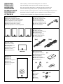
● Audio connection cord
● Câble de connexion audio
● Audio-Anschlußkabel
● Audio anslutningssladd
● Cavo di collegamento audio
● Cable de conexión de audio
● Audio aansluitkabel
● Speaker cords
● Câbles d’enceintes
● Lautsprecheranschlußkabel
● Högtalarledningar
● Cavi per gli altoparlanti
● Cables de los altavoces
● Luidsprekerdraden
● Mounting brackets
● Supports de montage
● Befestigungshalterungen
● Monteringsfästen
● Staffe di montaggio
● Ménsulas de instalación
● Montagesteunen
● Screws
● Vis
● Schrauben
● Skruvar
● Viti
● Tornillos
● Schroeven
● Main and rear speakers
● Enceintes principales et arrière
● Haupt- und hinteres Lautsprecherpaar
● Huvudhögtalare och bakre högtalare
● Altoparlanti principali e posteriori
● Altavoces principales y traseros
● Hoofdluidsprekers en achterluidsprekers
● Center speaker
● Enceinte centrale
● Centerlautsprecher
● Mitthögtalare
● Altoparlante centrale
● Altavoz central
● Middenluidspreker
● Subwoofer
● Subwoofer
● Subwoofer
● Subwooferhögtalaren
● Subwoofer
● Altavoz ultragraves
● Subwoofer
UNPACKING After unpacking, check that the following items are contained.
DEBALLAGE Après le déballage, vérifier que les pièces suivantes sont incluses.
AUSPACKEN Nach dem Auspacken überprüfen, ob die folgenden Teile vorhanden sind.
UPPACKNING Kontrollera efter det apparaten packats upp att följande delar finns med.
DISIMBALLAGGIO Verificare che tutte le parti seguenti siano contenute nell’imballaggio dell’apparecchio.
DESEMBALAJE Desembale el aparato y verifique que los siguientes accesorios están en la caja.
UITPAKKEN Controleer na het uitpakken of de volgende onderdelen voorhanden zijn.
(A)
(B)
[4m]
[15m]
(A)
(B)
(C)
X 3
X 2
X 5
X 8
X 2
X 3
X 2
<NX-220P><NX-220P><NX-220P><NX-220P>
<NX-C220>
<SW-P201>

English
E-1
●
To assure the finest performance, please read this manual
carefully. Keep it in a safe place for future reference.
●
Install the speakers in a cool, dry, clean place – away from
windows, heat sources, sources of excessive vibration,
dust, moisture and cold. Avoid sources of humming
(transformers, motors). To prevent fire or electrical shock,
do not expose the speakers to rain or water.
● To prevent the enclosure from warping or discoloring, do
not place the speakers where they will be exposed to
direct sunlight or excessive humidity.
● Do not place the following objects on the speakers:
Glass, china, etc.
If glass etc. falls by vibrations and breaks, it may cause
personal injury.
A burning candle etc.
If the candle falls by vibrations, it may cause fire and
personal injury.
A vessel with water in it
If the vessel falls by vibrations and water spills, it may
cause damage to the speakers, and/or you may get an
electric shock.
● Do not place the speakers where foreign objects such as
water drips might fall. It might cause a fire, damage to
the speakers, and/or personal injury.
● Do not place the speakers where they are liable to be
knocked over or struck by falling objects. Stable
placement will also ensure better sound performance.
● Placing the speakers on the same shelf or rack as the
turntable can result in feedback.
● Any time you note distortion, reduce the volume control
on your amplifier to a lower setting. Never allow your
amplifier to be driven into “clipping”. Otherwise the
speakers may be damaged.
●
When using an amplifier with a rated output power higher
than the nominal input power of the speakers, care should
be taken never to exceed the speakers’ maximum input.
● As these speakers contain strong magnets (though all of
them are magnetically shielded types), avoid placing
watches, magnetic tapes, etc. near them. Also, placing
the speakers near a TV set may impair picture color. If
this happens, move the speakers away from the TV set.
●
Do not attempt to clean the speakers with chemical solvents
as this might damage the finish. Use a clean, dry cloth.
● Secure placement or installation is the owner’s
responsibility.
YAMAHA shall not be liable for any accident caused
by improper placement or installation of speakers.
For SW-P201 only
● Never open the cabinet. If something drops into the set,
contact your dealer.
● Do not use force on switches, controls or connection
wires. When moving the unit, first disconnect the power
plug and the wires connected to other equipments.
Never pull the wires themselves.
● Be sure to read the “TROUBLESHOOTING” section
regarding common operating errors before concluding
that the unit is faulty.
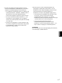
CAUTION: Read this before operating your unit.
Thank you for selecting this YAMAHA NS-P220 Speaker Package.
● When not planning to use this unit for a long period (ie.,
vacation, etc.), disconnect the AC power plug from the
wall outlet.
●
To prevent lightning damage, disconnect the AC power
plug when there is an electric storm.
● Since this unit has a built-in power amplifier, heat will
radiate from the rear panel. Place the unit apart from the
walls, allowing enough space above, behind and on the
both sides of the unit to prevent fire or damage.
Furthermore, do not position with the rear panel facing
down on the floor or other surfaces.
<For U.K. and Europe models only>
Be sure to allow a space of at least 20 cm above, behind
and on both sides of the unit.
● Super-bass frequencies reproduced by this unit may
cause a turntable to generate a howling sound. In such a
case, move this unit away from the turntable.
● If you hear distorted noise (i.e., unnatural, intermittent
“rapping” or “hammering” sounds) coming from this unit,
reduce the volume level. Extremely loud playing of a
movie soundtrack’s low frequency, bass-heavy sounds or
similarly loud popular music passages can damage this
speaker system.
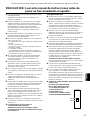
● VOLTAGE SELECTOR
(General model only)
The VOLTAGE SELECTOR on the
rear panel of this unit must be set
for your local main voltage
BEFORE plugging into the AC
main supply.
Voltages are 110-120/220-240 V
AC, 50/60 Hz.
Standby mode
If the POWER switch is set to the ON position and the
AUTO STANDBY switch is set to the HIGH or LOW
position, this unit turns into the standby mode when no
signal is inputted to this unit.
In this state, this unit is designed to consume a very
small quantity of power.
WARNING
TO REDUCE THE RISK OF FIRE OR ELECTRIC
SHOCK, DO NOT EXPOSE THIS UNIT TO RAIN OR
MOISTURE.
VOLTAGE
SELECTOR
220V-240V
110V-120V
For Canadian Customers
To prevent electric shock, match wide blade of plug to
wide slot and fully insert.
This Class B digital apparatus complies with Canadian
ICES-003.

E-2
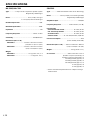
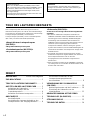
CONTENTS
UNPACKING.................... Inside of Front Cover
CAUTION .........................................................1
COMPONENTS OF THE PACKAGE .............. 2
SETTING UP THE SPEAKERS ...................... 3
Placing the subwoofer ................................... 3
Mounting the main and center speakers .......... 4
Mounting the rear speakers............................ 5
CONNECTIONS.............................................. 6
An example of basic connections .................... 6
How to connect speaker cords to the input
and output terminals of the speakers
............... 8
Connecting the subwoofer to speaker output
terminals of the amplifier................................ 9
USING THE SUBWOOFER (SW-P201)........ 10
Controls and their functions.......................... 10
Adjusting the subwoofer before use ................ 11
ADVANCED YAMAHA ACTIVE SERVO
TECHNOLOGY (for SW-P201) .................... 12
TROUBLESHOOTING.................................. 13
SPECIFICATIONS ........................................ 14
COMPONENTS OF THE PACKAGE
<Main/rear speakers (NX-220P)>
2-way acoustic-suspension speaker system
<Center speaker (NX-C220)>
2-way acoustic-suspension speaker system
<Subwoofer (SW-P201)>
Active Servo Processing Subwoofer System with a
built-in power amplifier
● This subwoofer system employs Advanced YAMAHA
Active Servo Technology which YAMAHA has developed
for reproducing higher quality super-bass sound. (Refer to
page 12 for details on Advanced YAMAHA Active Servo
Technology.) This super-bass sound adds a more
realistic, theater-in-the-home effect to your stereo system.
● This subwoofer can be easily added to your existing
audio system by connecting to either the speaker
terminals or the line output (pin jack) terminals of the
amplifier.
● The AUTO STANDBY switch saves you the trouble of
setting the POWER switch to the ON or OFF position.
The speaker package “NS-P220” is designed for use in a
multi-channel audio system such as a home theater system.
The package includes two pairs of main/rear speakers (NX-
220P), a center speaker (NX-C220) and a subwoofer
system (SW-P201).
SPECIAL INSTRUCTIONS FOR U.K. MODEL
IMPORTANT:
THE WIRES IN MAINS LEAD ARE COLOURED IN
ACCORDANCE WITH THE FOLLOWING CODE:
Blue: NEUTRAL
Brown: LIVE
As the colours of the wires in the mains lead of this
apparatus may not correspond with the coloured markings
identifying the terminals in your plug, proceed as follows:
The wire which is coloured BLUE must be connected to
the terminal which is marked with the letter N or coloured
BLACK. The wire which is coloured BROWN must be
connected to the terminal which is marked with the letter L
or coloured RED. Making sure that neither core is
connected to the earth terminal of the three pin plug.
For U.K. customers
If the socket outlets in the home are not suitable for the plug
supplied with this appliance, it should be cut off and an
appropriate 3 pin plug fitted. For details, refer to the
instructions described below.
Note: The plug severed from the mains lead must be
destroyed, as a plug with bared flexible cord is hazardous if
engaged in a live socket outlet.

English
E-3
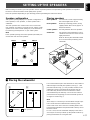
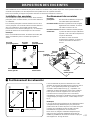
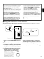
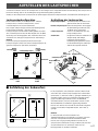
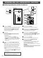
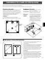
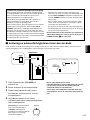
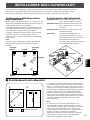
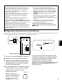
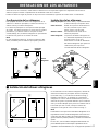
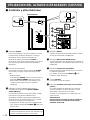
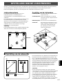
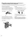
m Placing the subwoofer
It is recommended to place the subwoofer on the outside of
either the right or the left main speaker. (See fig. Å .) The
placement shown in fig. ı is also possible, however, if the
subwoofer system is placed directly facing the wall, the
bass effect may die because the sound from it and the
sound reflected by the wall may cancel out each other. To
prevent this from happening, face the subwoofer system at
an angle as shown in fig. Å.
Note
There may be a case that you cannot obtain enough super-
bass sounds from the subwoofer when listening in the
center of the room. This is because “standing waves” have
been developed between two parallel walls and they cancel
the bass sounds.
In such a case, face the subwoofer obliquely to the wall. It
also may be necessary to break up the parallel surfaces by
placing bookshelves etc. along the walls.
( : Subwoofer, : Main speaker)
ı
Å
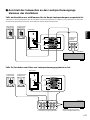
SETTING UP THE SPEAKERS
Before making connections, place all speakers in their respective positions. The positioning of the speakers is important
because it controls the whole sound quality of this system.
Place the speakers depending on your listening position by following the instructions below.
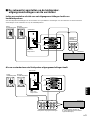
Speaker configuration
This speaker package employs a 6 speaker configuration: 2
main speakers, 2 rear speakers, a center speaker and a
subwoofer.
The main speakers are used for main source sound. The
rear speakers are used for surround sounds, and the center
speaker is for center sounds (dialog etc.). The subwoofer is
for reinforcing low frequencies on your audio system.
Note
In this speaker package, the same speakers (NX-220P) are
used for the main and rear speakers.
Placing speakers
Main speakers: On both sides of and at approximately
the same height as the TV set.
Rear speakers: Behind your listening position, facing
slightly inward. About 1.8 m (approx. 6
feet) from the floor.
Center speaker: Precisely between the main speakers.
Subwoofer: The position of the subwoofer is not so
critical because low bass tones are not
highly directional.
Refer to “Placing the subwoofer” below
for a recommended positioning of the
subwoofer.
Main L Center Main R
Rear L
Subwoofer
Rear R
Main L
Main R
Subwoofer
Center
Rear L
Rear R
TV-set

E-4
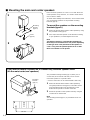
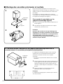
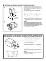
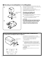
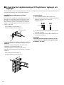
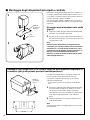
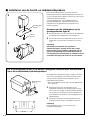
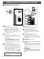
Place the main speakers on a rack or on a shelf. Place the
center speaker on top of the TV, on a shelf or inside the TV
rack so that it is stable.
To obtain more stability and usefulness, we recommend that
you mount these speakers on the provided mounting
brackets (type A).
To mount the speakers on the mounting
brackets (type A)
1 Attach the bracket to the bottom of the speaker by using
the provided screw (type A).
2 Turn and/or slide the speaker on the bracket according
to your preference, and then tighten the screw.
Note
Though this speaker is a magnetically shielded type,
there may be some influence on a TV picture depending
on the type of TV or the placement of the speaker. In
such a case, place the speaker apart from TV so that
there is no influence on TV picture.
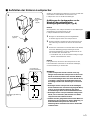
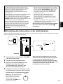
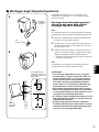
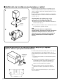
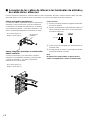
m Mounting the main and center speakers
1
2
The provided mounting bracket (type C) with 1 pair of
screw holes (at an interval of 60 mm) can be used to
mount the speaker on a speaker stand.
* Those screw holes can be used with M4 screws only.
1 Attach the bracket to the bottom of the speaker by
using the provided screw (type A) so that the convex
part of the bracket fits in the grooved part on the
bottom of the speaker as shown on the left.
2 Mount the speaker on the speaker stand by using the
screw holes on the bracket.
Note
The mounting bracket (type C) is provided for each of 5
speakers.
If you want to mount a speaker on a commercially available speaker stand
(for the main/center/rear speakers)
Mounting
bracket
(type A)
Screw
(type A)
Mounting
bracket
(type C)
Screw
(type A)
60 mm

English
E-5
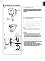
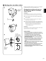
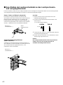
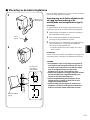
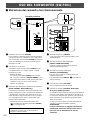
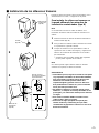
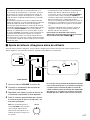
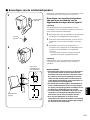
Mount the rear speakers on a shelf, rack or directly on the
floor, or hang them on the wall.
To mount the rear speakers on a wall by
using the provided mounting brackets
(type B)
Note
It is recommended that you connect the speaker cords to
the speaker’s terminals before attaching the bracket to the
speaker.
1 Attach the bracket to the bottom of the speaker by using
the provided screw (type B).
2 Turn and/or slide the speaker on the bracket according
to your preference, and then, tighten the screw.
3 Fasten screws into a firm wall or wall support as shown
in the figure, and hang the holes of the mounting
bracket on the protruding screws.
* Make sure that the screws are securely caught by the
narrow parts of the holes.
Note
If desired, you can hang the speaker directly on the
protruding screws on the wall without using the bracket.
WARNING
● Each speaker weighs 0.7 kg (1 lbs. 9 oz.). Do not
mount them on thin plywood or a wall with soft
surface material. If mounted, the screws may come
out of the flimsy surface and the speakers may fall.
This damages the speakers or causes personal
injury.
● Do not install the speakers to a wall with nails,
adhesives, or any other unstable hardware. Long-
term use and vibrations may cause them to fall.
● To avoid accidents resulting from tripping over loose
speaker cords, fix them to the wall.
● Select a proper position on the wall to mount the
speaker and the bracket so that no one will injure his/
her head or face with the edge of the bracket.
m Mounting the rear speakers
1
2
3
Mounting
bracket
(type B)
Screw
(type B)
Mounting
bracket
(type B)
Wall/ wall
support
Tapping screw
(Available at the
hardware store)
Min.
20 mm
65 mm

E-6
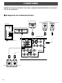
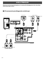
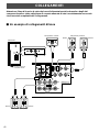
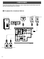
CONNECTIONS
Caution: Plug in the subwoofer and other audio/video components after all connections are
completed.
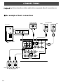
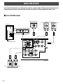
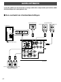
m An example of basic connections
SPEAKERS
MAIN CENTER REAR
(SURROUND)
OUTPUT
SUB
WOOFER
CAUTION
SEE INSTRUCTION
MANUAL FOR CORRECT SETTING.
MAIN
A
B
A
B
CENTER REAR
(SURROUND)
/MONO
VOLUME
INPUT1
FROM AMPLIFIER
OUTPUT
TO SPEAKERS
INPUT2
AUTO
STANDBY
STANDBY-RED
ON-GREEN
OFF
LOW
HIGH
OFF
POWER
ON
0I0
INPUT2
/MONO
REAR R
REAR L
REAR R
CENTER
REAR L
CENTER
FRONT R
FRONT R
FRONT L
FRONT L
LeftRight
Subwoofer
Amplifier
To AC outlet
Center speaker
Rear speakers
LeftRight
Main speakers

English
E-7
● Connect the main, center and rear speakers to the
speaker output terminals of your amplifier with the
provided speaker cords.
* The provided speaker cords have labels marked
FRONT L, FRONT R, CENTER, REAR L or REAR R.
Connect each speaker cord to the corresponding
speaker by following the figure on page 6.
* Connect each speaker making sure not to reverse the
polarity (+, –). If the speaker is connected with
reversed polarity, the sound will be unnatural and lack
bass.
* For the main and rear speakers only, connect one
speaker to the left (marked L) terminals of your
amplifier, and another speaker to the right (marked R)
terminals.
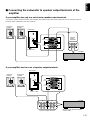
● Basically, connect the subwoofer to the line output (pin
jack) terminal(s) of the amplifier. If your amplifier does
not have any line output terminal, connect the subwoofer
to the speaker output terminals of the amplifier. (Refer to
page 9 for details.)
* To connect with a YAMAHA DSP amplifier (or AV
receiver), connect the SUBWOOFER (or LOW PASS
etc.) terminal on the rear of the DSP amplifier (or AV
receiver) to the L/MONO INPUT2 terminal of the
subwoofer.
* To connect the subwoofer to the SPLIT SUBWOOFER
terminals on the rear of the DSP amplifier, connect
them to both the left L and right R INPUT2 terminals
of the subwoofer.
Note
When connecting to a monaural line output terminal of the
amplifier, connect the L/MONO INPUT2 terminal.

E-8
Main/center/rear speakers
One side of the provided speaker cord has a white broken
line and the other side has no line.
Connect the (+) terminals on both the speaker and the
amplifier using the side with a white broken line. Connect
the (–) terminals on both components using the side with no
line.
Red: positive (+)
Black: negative (–)
Subwoofer (INPUT1/OUTPUT terminals)
Connect the (+) terminals on both the subwoofer and the
amplifier using one side of the cord. Connect the (–)
terminals on both components using the other side of the
cord.
Red: positive (+)
Black: negative (–)
m How to connect speaker cords to the input and output terminals
of the speakers
For connections, keep the speaker cords as short as possible. Do not bundle or roll up the excess part of the cords. If the
connections are faulty, no sound will be heard from the speakers.
10 mm
How to Connect:
1 Press and hold the terminal’s tab, as shown in the
figure.
2 Insert the bare wire end properly into the terminal hole.
[Remove approx. 10 mm (3/8”) insulation from the
speaker cord.]
3 Release your finger from the tab to allow it to lock
securely on the cord’s wire end.
4 Test the firmness of the connection by pulling lightly on
the cord at the terminal.
Note
Do not let the bare speaker wires touch each other as
this could damage the speaker or the amplifier, or both
of them.
White broken line

English
E-9
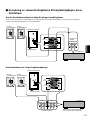
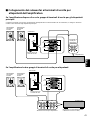
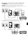
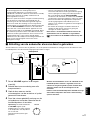
m Connecting the subwoofer to speaker output terminals of the
amplifier
If your amplifier has only one set of main speaker output terminals
Connect the speaker output terminals of the amplifier to the INPUT1 terminals of the subwoofer, and connect the OUTPUT
terminals of the subwoofer to the main speakers.
Left main
speaker
Right main
speaker
Subwoofer
Amplifier
Speaker
output
terminals
To AC outlet
If your amplifier has two sets of speaker output terminals
(Both A and B speaker outputs
must be ON.)
Subwoofer
Amplifier
Speaker output terminals
To AC outlet
/MONO
VOLUME
INPUT1
FROM AMPLIFIER
OUTPUT
TO SPEAKERS
INPUT2
AUTO
STANDBY
STANDBY-RED
ON-GREEN
OFF
LOW
HIGH
OFF
POWER
ON
0I0
INPUT1
FROM AMPLIFIER
OUTPUT
TO SPEAKERS
/MONO
VOLUME
INPUT1
FROM AMPLIFIER
OUTPUT
TO SPEAKERS
INPUT2
AUTO
STANDBY
STANDBY-RED
ON-GREEN
OFF
LOW
HIGH
OFF
POWER
ON
0I0
AB
INPUT1
FROM AMPLIFIER
OUTPUT
TO SPEAKERS
Left main
speaker
Right main
speaker

E-10
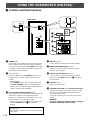
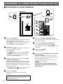
USING THE SUBWOOFER (SW-P201)
1 POWER switch
Set this switch to the ON position to turn on the power
of the subwoofer. When the power of the subwoofer is
on, the power indicator below the POWER switch lights
up GREEN. Set this switch to the OFF position to turn
off the power of the subwoofer.
2 Power indicator
Lights up GREEN when the POWER switch is set to
the ON position and goes off when set to the OFF
position.
* Standby mode
If the POWER switch is set to the ON position and
the AUTO STANDBY switch is set to the HIGH or
LOW position, this indicator lights up RED when no
signal is inputted to the subwoofer.
3 AUTO STANDBY (HIGH/LOW/OFF) switch
By setting this switch to the HIGH or LOW position, the
subwoofer’s automatic power-switching function
operates as described on the next page. If you do not
need this function, set to the OFF position.
* Make sure to change the setting of this switch only
when the POWER switch (1) is in the OFF
position.
Standby mode
The subwoofer is still using a small amount of power
in this mode.
4 INPUT2 terminals
Used to input line level signals from the amplifier.
5 INPUT1 (FROM AMPLIFIER) terminals
Used to connect the subwoofer with the speaker
terminals of the amplifier.
6 OUTPUT (TO SPEAKERS) terminals
Can be used for connecting to the main speakers.
Signals from the INPUT1 terminals (5) are sent to
these terminals.
7 VOLUME control
Adjusts the volume level.
8 VOLTAGE SELECTOR switch (General model only)
If the preset setting of the switch is incorrect, set the
switch to the proper voltage range (220V-240V or
110V-120V) of your area.
Consult your dealer if you are unsure of the correct
setting.
WARNING
Be sure to unplug the subwoofer before setting the
VOLTAGE SELECTOR switch correctly.
Rear panel
m Controls and their functions
INPUT1
FROM AMPLIFIER
OUTPUT
TO SPEAKERS
INPUT2
/MONO
AUTO
STANDBY
STANDBY-RED
ON-GREEN
OFF
LOW
HIGH
OFF
POWER
ON
1
VOLUME
0I0
OFF
POWER
ON
5
6
4
INPUT1
FROM AMPLIFIER
OUTPUT
TO SPEAKERS
INPUT2
/MONO
AUTO
STANDBY
STANDBY-RED
ON-GREEN
OFF
LOW
HIGH
VOLUME
0I0
2
3
7
VOLTAGE
SELECTOR
220V-240V
110V-120V
VOLTAGE
SELECTOR
220V-240V
110V-120V
8

English
E-11
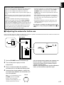
1 Set the VOLUME control to minimum (0).
2 Turn on the power supply to all the
components.
3 Play a source and adjust the amplifier’s
volume control to the desired listening level.
4 Increase the volume gradually to adjust the
volume balance between the subwoofer and
the main speakers.
Note: It is recommended to set the
VOLUME control to the middle
position when using all the
speakers of this package in a 5.1-
channel home theater system.
䡵 Adjusting the subwoofer before use
Before using the subwoofer, adjust the subwoofer to obtain the optimum volume balance between the subwoofer and the main
speakers by following the procedures described below.
Rear panel
Once the volume balance between the subwoofer and
the main speakers is adjusted, you can adjust the
volume of your whole sound system by using the
amplifier’s volume control.
However, if you change the main speakers NX-220P to
others, you must make this adjustment again.
INPUT1
FROM AMPLIFIER
OUTPUT
TO SPEAKERS
INPUT2
/MONO
AUTO
STANDBY
STANDBY-RED
ON-GREEN
OFF
LOW
HIGH
OFF
POWER
ON
2
VOLUME
0I0
OFF
POWER
ON
AUTO
STANDBY
STANDBY-RED
ON-GREEN
OFF
LOW
HIGH
VOLUME
0I0
1, 4
VOLUME
0I0
Automatic power-switching function
If the source being played is stopped and the input signal is
cut off for 7 to 8 minutes, the subwoofer automatically
switches to the standby mode. (When the subwoofer
switches to the standby mode, the power indicator lights up
in red.)
When you play a source again, the power of the subwoofer
turns on automatically by sensing audio signals input to the
subwoofer.
This function operates by sensing a certain level of low
frequency input signal. Usually set the AUTO STANDBY
switch to the LOW position. However, if the power is not
switched to ON or STANDBY smoothly, set the switch to the
HIGH position. In the HIGH position, the power will turn on
even with a low level of input signal. But please be aware
that the subwoofer may not switch to the standby mode
when there is an extremely low input signal.
* The power might turn on unexpectedly by sensing noise
from other appliances. If that occurs, set the AUTO
STANDBY switch to the OFF position and use the
POWER switch to switch the power between ON and
OFF manually.
* This function detects the low-frequency components
below 200 Hz of the input signals (i.e., the explosion in
the action movie, the sound of the bass guitar or the
bass drum, etc.).
* The minutes required to switch the subwoofer to the
standby mode might change by sensing noise from
other appliances.
This function is available only when the power of the
subwoofer is on (by setting the POWER switch (
1) to
“ON”).

E-12
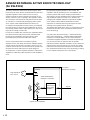
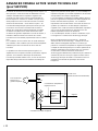
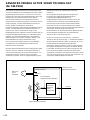
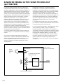
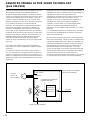
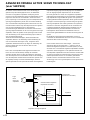
ADVANCED YAMAHA ACTIVE SERVO TECHNOLOGY
(for SW-P201)
The theory of Yamaha Active Servo Technology has been
based upon two major factors, the Helmholtz resonator and
negative-impedance drive. Active Servo Processing
speakers reproduce the bass frequencies through an “air
woofer”, which is a port or opening in the speaker’s cabinet.
This opening is used instead of, and performs the functions
of, a woofer in a conventionally designed speaker system.
Thus, signals of low amplitude within the cabinet can,
according to the Helmholtz resonance theory, be outputted
from this opening as waves of great amplitude if the size of
the opening and the volume of the cabinet are in the correct
proportion to satisfy a certain ratio.
In order to accomplish this, moreover, the amplitudes within
the cabinet must be both precise and of sufficient power
because these amplitudes must overcome the “load”
presented by the air that exists within the cabinet.
Thus it is this problem that is resolved through the
employment of a new design in which the amplifier supplies
special signals. If the electrical resistance of the voice coil
could be reduced to zero, the movement of the speaker unit
would become linear with respect to signal voltage. To
accomplish this, a special negative-impedance output-drive
amplifier for subtracting output impedance of the amplifier is
used.
By employing negative-impedance drive circuits, the
amplifier is able to generate precise, low-amplitude, low-
frequency waves with superior damping characteristics.
These waves are then radiated from the cabinet opening as
high-amplitude signals. The system can, therefore, by
employing the negative-impedance output drive amplifier
and a speaker cabinet with the Helmholtz resonator,
reproduce an extremely wide range of frequencies with
amazing sound quality and less distortion.
The features described above, then, are combined to be the
fundamental structure of the conventional Yamaha Active
Servo Technology.
Our new Active Servo Technology — Advanced Yamaha
Active Servo Technology — adopted Advanced Negative
Impedance Converter (ANIC) circuits, which allows the
conventional negative impedance converter to dynamically
vary in order to select an optimum value for speaker
impedance variation. With this new ANIC circuits, Advanced
Yamaha Active Servo Technology can provide more stable
performance and improved sound pressure compared with
the conventional Yamaha Active Servo Technology, resulting
in more natural and dynamic bass reproduction.
High-amplitude
bass sound
Cabinet
Port
Air woofer
(Helmholtz resonator)
Active Servo
Processing
Amplifier
Signals
Signals of low amplitude
Advanced Negative-
impedance Converter

English
E-13
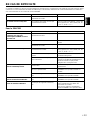
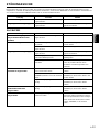
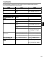
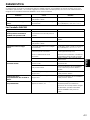
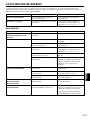
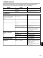
Problem
Power is not supplied even
though the POWER switch is set
to the ON position.
No sound.
Sound level is too low.
The subwoofer will not turn on
automatically.
The subwoofer turns into the
standby mode unexpectedly.
The subwoofer turns on
unexpectedly.
What to Do
Connect it securely.
Turn the VOLUME control to the right.
Connect them securely.
Connect them correctly, that is L (left) to
L, R (right) to R, “+” to “+” and “–” to “–”.
Play a source sound with bass
frequencies.
Reposition the subwoofer or break up
the parallel surface by placing
bookshelves etc. along the walls.
Set the POWER switch to the ON
position.
Set the AUTO STANDBY switch to the
“HIGH” or “LOW” position.
Set the AUTO STANDBY switch to the
“HIGH” position.
Set the AUTO STANDBY switch to the
“HIGH” position.
Move the subwoofer farther away from
such appliances and/or reposition the
connected speaker cables.
Otherwise, set the AUTO STANDBY
switch to the “OFF” position.
Cause
The power plug is not securely
connected.
The VOLUME control is set to 0.
Speaker cords are not connected
securely.
Speaker cords are not connected
correctly.
A source sound with few bass
frequencies is played.
It is influenced by standing waves.
The POWER switch is set to the OFF
position.
The AUTO STANDBY switch is set to
the OFF position.
The level of input signal is too low.
The level of input signal is too low.
There is an influence of noise
generated from external appliances etc.
TROUBLESHOOTING
Refer to the chart below when this unit does not function properly. If the problem you are experiencing is not listed below or if
the instructions given below do not help, disconnect the power cord and contact your authorized YAMAHA dealer or service
center.
Problem
No sound.
Sound level is too low.
What to Do
Connect them securely.
Connect them correctly, that is L (left) to
L, R (right) to R, “+” to “+” and “–” to “–”.
Cause
Speaker cords are not connected
securely.
Speaker cords are not connected
correctly.
For SW-P201

E-14
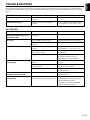
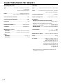
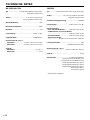
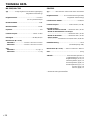
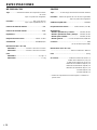
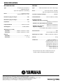
SPECIFICATIONS
NX-220P, NX-C220
Type ............... 2-way acoustic-suspension speaker system
Magnetically shielded type
Driver............................................. 8 cm (3-1/8”) cone type
1.9 cm (3/4”) balanced dome type
Nominal Input Power ................................................. 30W
Maximum Input Power ............................................. 100W
Impedance .....................................................................6Ω
Frequency Response................................ 140 Hz–27 kHz
Sensitivity ...................................................86 dB/2.83V/m
Dimensions (W x H x D)
<NX-220P>........................100 mm x 140 mm x 113 mm
(3-15/16” x 5-1/2” x 4-7/16”)
<NX-C220> .......................140 mm x 100 mm x 112 mm
(5-1/2” x 3-15/16”x 4-7/16”)
Weight
<NX-220P>.................................. 0.7 kg (1 lbs. 9 oz.) x 4
<NX-C220> ....................................... 0.7 kg (1 lbs. 9 oz.)
SW-P201
Type ............... Advanced Yamaha Active Servo Technology
Driver...................... 16 cm (6-5/16”) cone woofer (JA1678)
Magnetically shielded type
Amplifier Output.................................................... 50W/5Ω
Frequency Response................... 30 Hz–200 Hz (–10 dB)
Power Supply
USA and Canada models ....................... AC 120V, 60 Hz
U.K. and Europe models ........................ AC 230V, 50 Hz
Australia model.......................................AC 240V, 50 Hz
General model.............. AC 110-120/220-240V, 50/60 Hz
Power Consumption ...................................................42W
(In the standby mode: 6W)
Dimensions (W x H x D)...... 200 mm x 395 mm x 384 mm
(7-7/8” x 15-9/16” x 15-1/8”)
Weight .................................................9.3 kg (20 lbs. 7 oz.)
Accessories ...............................Audio connection cord x 1
Speaker cord [4 m (13.1 feet)] x 3
Speaker cord [15 m (49.2 feet)] x 2
Mounting bracket (type A) x 3
Mounting bracket (type B) x 2
Mounting bracket (type C) x 5
Screw (type A) x 8
Screw (type B) x 2
* Please note that all specifications are subject to change
without notice.

Français
F-1
●
Pour garantir les meilleures performances possibles, lire
ce manuel avec attention. Le garder dans un endroit sûr
pour une utilisation ultérieure.
●
Installer ces enceintes dans un endroit frais, sec et propre,
loin de fenêtres, sources de chaleur et d’endroits où les
vibrations, la poussière, l’humidité ou le froid sont
importants. Eviter les sources de bourdonnements
(transformateurs, moteurs). Pour éviter les incendies ou
électrocution, ne pas exposer ces enceintes à la pluie ni à
l’humidité.
● Pour éviter que le coffret se gondole ou se décolore, ne
pas placer les enceintes à un endroit ou elles seront
exposées aux rayons directs du soleil ou à une trop forte
humidité.
● Ne placez pas les objets suivants sur les enceintes:
Verres, porcelaine, etc.
Si les verres, etc., tombent sous l’effet des vibrations et
se rompent, ceci risque de causer des blessures.
Une bougie allumée, etc.
Si la bougie tombe sous l’effet des vibrations, ceci
risque de causer un incendie et des blessures.
Un récipient contenant de l’eau
Si le récipient tombe sous l’effet des vibrations et que
l’eau se répand, ceci risque d’endommager les
enceintes et/ou de causer une électrocution.
● Ne pas placer les enceintes dans un endroit où des corps
étrangers comme des gouttes d'eau peuvent tomber.
Ceci peut causer un feu, des dommages aux enceintes
et/ou une blessure corporelle.
● Ne pas placer les enceintes à un endroit où elles
risquent d’être renversées ou percutées par des objets
tombants. Un endroit bien stable améliorera aussi la
qualité du son.
● Si les enceintes sont placées sur la même étagère ou
dans le même meuble que le tourne-disque, un effet de
retour sonore risquera de se produire.
● Si des distorsions sonores se produisent, réduire le
niveau sonore en baissant la commande de volume de
l’amplificateur. Ne jamais laisser de “pincement” sonore
se produire sur l’amplificateur. Sinon, les enceintes
risqueront d’être endommagées.
●
Lorsqu’on utilise un amplificateur dont la puissance de
sortie nominale est supérieure à la puissance d’entrée
nominale des enceintes, il faut veiller à ne pas dépasser
l’entrée maximale des enceintes.
● Ces enceintes contenant des aimants puissants (bien
que tous les modèles aient un blindage
antimagnétique), éviter de placer des montres, des
bandes magnétiques, etc. à proximité des enceintes. En
outre, si l’on place les enceintes à proximité d’un
téléviseur, les couleurs des images risqueront d’être
affectées. Dans ce cas, éloigner les enceintes du
téléviseur.
●
Ne pas essayer de nettoyer ces enceintes avec des diluants
chimiques, ceci endommagerait le fini. Utiliser un chiffon
propre et sec.
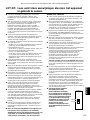
PRECAUTIONS D’USAGE:Tenir compte des precautions ci-dessous avant de
faire fonctionner l’appareil.
Nous vous remercions d’avoir porté votre choix sur ce ensemble d’enceintes NS-P220 de YAMAHA.
● Le propriétaire du système est entièrement
responsable du bon positionnement et de la bonne
installation du système.
YAMAHA décline toute responsabilité en cas
d’accident causé par un positionnement ou une
installation inadéquats des enceintes.
Pour SW-P201 seulement
● Ne jamais ouvrir le coffret. Si un objet pénètre dans
l’appareil, contacter son revendeur.
● Ne pas forcer les commutateurs, les touches ou les
câbles de raccordement.
Lors du déplacement de l’appareil, d’abord débrancher
la prise d’alimentation et les câbles le raccordant à
d’autres appareils. Ne jamais tirer sur les cordons.
● Bien lire la section “EN CAS DE DIFFICULTE”
concernant les erreurs de fonctionnement communes
avant de conclure que votre appareil est en panne.
● Lorsqu’on prévoit de ne pas utiliser cet appareil pendant
longtemps (pendant les vacances, par exemple),
débrancher le cordon d’alimentation CA de la prise
murale.
●
Pour prévenir tout dégât dû à la foudre, débrancher la
prise d’alimentation CA en cas d’orage.
● Cet appareil possédant un amplificateur intégré, de la
chaleur sera irradiée par le panneau arrière. Par
conséquent, placer l’appareil à une certaine distance
des murs, en laissant suffisamment d’espace au-dessus,
derrière et des deux côtés de l’appareil afin d’éviter tout
risque de dommage ou d’incendie. Ne pas positionner
non plus cet appareil dos au plancher ou à une autre
surface.
<Modèles pour le Royaume-Uni et l’Europe
seulement>
Laisser un espace d’au moins 20 cm au-dessus, derrière
et des deux côtés de l’appareil.
● Les sons de très basse fréquence produits par cet
appareil peuvent provoquer un sifflement sur le tourne-
disque. Dans ce cas, éloigner cet appareil du tourne-
disque.
● Si une distorsion se fait entendre (par exemple des
petits coups secs intermittents ou un “martèlement”) sur
cet appareil, diminuer le niveau sonore. La lecture à très
haut volume des sons de basse ou des sons de basses
fréquences de la bande sonore d’un film, ou de
passages de musique populaire de forte intensité, sont
susceptibles d’endommager ce système d’enceintes.
● Sélecteur de tension (VOLTAGE
SELECTOR) (modèle général
seulement)
Le sélecteur de tension sur le
panneau arrière de cet appareil
doit être réglé sur votre tension
locale AVANT de brancher
l’appareil sur une prise de
courant CA
Les tensions sont de 110-120/220-
240V CA 50/60 Hz.
VOLTAGE
SELECTOR
220V-240V
110V-120V

F-2
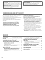
TABLE DES MATIERES
DEBALLAGE ........ Intérieur du couvercle avant
PRECAUTIONS D’USAGE ..............................1
ELEMENTS DE L’ENSEMBLE ....................... 2
DISPOSITION DES ENCEINTES ................... 3
Positionnement du subwoofer ........................ 3
Montage des enceintes principales
et centrale..........................................................
4
Montage des enceintes arrière ....................... 5
CONNEXIONS ................................................ 6
Exemple de raccordement de base ................. 6
Raccordement des cordons d’enceintes aux
bornes d’entrée et de sortie des enceintes
....... 8
Raccordement du subwoofer aux bornes de
sortie d’enceintes de l’amplificateur
................ 9
UTILISATION DU SUBWOOFER
(SW-P201) .................................................... 10
Les commandes et leurs fonctions ................ 10
Réglage du subwoofer avant l’utilisation ........ 11
ADVANCED YAMAHA ACTIVE SERVO
TECHNOLOGY (pour SW-P201) ................. 12
EN CAS DE DIFFICULTE ..............................13
CARACTERISTIQUES TECHNIQUES ......... 14
ELEMENTS DE L’ENSEMBLE
Mode veille
Si l’interrupteur POWER est mis sur la position ON et le
commutateur AUTO STANDBY sur la position HIGH ou
LOW, cet appareil passe en mode veille lorsqu’aucun
signal ne parvient à cet appareil.
Dans cet état, l’appareil consomme une très faible
quantité de courant.
AVERTISSEMENT
AFIN D’ÉVITER TOUT RISQUE D’INCENDIE OU
D’ÉLECTROCUTION, NE PAS EXPOSER L’APPAREIL
À LA PLUIE NI À L’HUMIDITÉ
L’ensemble d’enceintes “NS-P220” est conçu pour être
utilisé avec un système audio multi-canaux, tel qu’une
installation Home Cinéma. L’ensemble comprend deux
paires d’enceintes principales/arrière (NX-220P), une
enceinte centrale (NX-C220), et un subwoofer (SW-P201).
<Enceintes principales/arrière (NX-220P)>
Enceinte à suspension acoustique à deux voies
<Enceinte centrale (NX-C220)>
Enceinte à suspension acoustique à deux voies
<Subwoofer (SW-P201)>
Subwoofer à Active Servo Processing avec
amplificateur incorporé
● Ce subwoofer utilise Advanced YAMAHA Active Servo
Technology mise au point par YAMAHA pour la
reproduction de basses fréquences de meilleure qualité.
(Pour ce qui concerne Advanced YAMAHA Active Servo
Technology, se reporter à la page 12.) Ces basses
fréquences ajoutent un effet réaliste cinématographique
aux sons fournis par une chaîne stéréo.
● Ce subwoofer peut être facilement ajouté à votre chaîne
actuelle en le raccordant soit aux bornes d’enceintes soit
aux bornes de sortie de ligne (fiche Cinch) de
l’amplificateur.
● Le commutateur AUTO STANDBY vous évite d’avoir à
régler l’interrupteur POWER sur la position ON ou OFF.
POUR LES CONSOMMATEURS CANADIENS
Pour eviter les chocs electriques, introduire la lame la
plus large de la fiche dans la borne correspondante de
la prise et pousser jusqu’au fond.
Cet appareil numérique de la classe B est conforme à la
norme NMB-003 du Canada.

Français
F-3
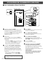
m Positionnement du subwoofer
Il est recommandé de placer le subwoofer sur le côté
extérieur de l’enceinte principale droite ou gauche. (Voir la
fig. Å .) Il est également possible de positionner les
enceintes comme indiqué à la fig. ı ; cependant, si le
subwoofer est placé directement contre le mur, l’effet de
basse pourra se trouver supprimé car le son émis par
l’enceinte et le son renvoyé par le mur s’annuleront
mutuellement. Pour éviter ce problème, placer le subwoofer
à angle oblique par rapport au mur, comme indiqué sur la
fig. Å.
Remarque
Les sons de très basses fréquences du subwoofer peuvent
quelquefois être trop faiblement perçus à partir d’une
position d’écoute en milieu de pièce. Les ondes renvoyées
par deux murs parallèles peuvent en effet s’annuler
mutuellement et supprimer les sons de basses.
Dans un tel cas, diriger le subwoofer obliquement par
rapport au mur. Il peut être également nécessaire de
modifier le parallélisme des surfaces murales en plaçant
des étagères etc. le long des murs.
( : Subwoofer, : enceinte principale)
ı
Å
DISPOSITION DES ENCEINTES
Avant d’effectuer les raccordements, bien placer toutes les enceintes à leur position respective. Le bon positionnement des
enceintes est important, car de lui dépend la bonne qualité sonore du système tout entier.
Placer les enceintes par rapport à la position d’écoute en suivant les instructions ci-dessous.
Installation des enceintes
Cet ensemble est composé de 6 enceintes: deux enceintes
principales, deux enceintes arrière, une enceinte centrale et
un subwoofer.
Les enceintes principales assurent l’émission du son de la
source principale. Les enceintes arrière assurent l’émission
des sons d’ambiance, et l’enceinte centrale assure
l’émission des sons centraux (dialogue, etc.). Le subwoofer
permet de renforcer les basses fréquences de la chaîne.
Remarque
Dans cet ensemble d’enceintes, les mêmes enceintes (NX-
220P) sont utilisées pour les enceintes principales et
arrière.
Positionnement des enceintes
Enceintes
principales:
Des deux côtés du téléviseur et à peu près
à la même hauteur que le téléviseur.
Enceintes arrière: Derrière la position d’écoute, dirigées
légèrement vers l’intérieur. A environ
1,8 mètres au-dessus du sol.
Enceinte centrale:
Exactement au milieu des enceintes principales.
Subwoofer:
La position du subwoofer n’est pas extrêmement
importante, car les sons de basses fréquences ne
sont pas très directionnels.
Pour obtenir un conseil concernant le
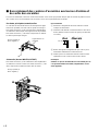
positionnement du subwoofer, se reporter à la
section “Positionnement du subwoofer” ci-
dessous.
Enceinte
principale gauche
Enceinte
centrale
Enceinte
principale droite
Enceinte
arrière gauche
Subwoofer
Enceinte
arrière droite
Subwoofer
Téléviseurs
Enceinte
centrale
Enceinte
principale gauche
Enceinte
arrière droite
Enceinte
arrière gauche
Enceinte
principale
droite

F-4
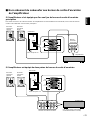
Placer les enceintes principales sur un casier ou une
étagère. Placer l’enceinte centrale sur le téléviseur, sur une
étagère, ou dans le casier du téléviseur de manière qu’il
bien stable.
Pour obtenir une meilleure stabilité et une meilleure
commodité, nous conseillons de monter ces enceintes sur
les supports de montage fournis (type A).
Pour monter les enceintes sur les
supports de montage (type A)
1 Fixer le support au bas de l’enceinte en utilisant la vis
fournie (type A).
2 Faire tourner et/ou glisser l’enceinte sur le support
comme voulu, puis serrer la vis.
Remarque
Bien que cette enceinte soit de type à blindage anti-
magnétique, la réception du téléviseur peut être altérée
dépendant du type du téléviseur ou de l’emplacement
de l’enceinte. Dans ce cas, placer l’enceinte
suffisamment loin du téléviseur pour que l’image de ce
dernier ne soit pas affectée.
m Montage des enceintes principales et centrale
1
2
Le support de montage fourni (type C) avec une paire
d’orifices de vis (à un intervalle de 60 mm) peut être
utilisé pour de monter l’enceinte sur un support
d’enceinte.
* Ces trous de vis peuvent être utilisés avec les vis M4
seulement.
1 Fixer le support au bas de l’enceinte en utilisant la vis
fournie (type A) de manière que la partie convexe du
support s’engage dans la rainure située au bas de
l’enceinte, comme indiqué sur l’illustration ci-contre à
gauche.
2 Monter l’enceinte sur le support d’enceinte en
utilisant les orifices de vis du support.
Remarque
Le support de montage (type C) est fourni pour chacune
des cinq enceintes.
Si l’on désire monter l’enceinte sur un support d’enceinte disponible dans le
commerce (pour les enceintes principales/centrale/arrière)
Support de
montage
(type A)
Vis
(type A)
Support de
montage
(type C)
Vis
(type A)
60 mm
Seite wird geladen ...
Seite wird geladen ...
Seite wird geladen ...
Seite wird geladen ...
Seite wird geladen ...
Seite wird geladen ...
Seite wird geladen ...
Seite wird geladen ...
Seite wird geladen ...
Seite wird geladen ...
Seite wird geladen ...
Seite wird geladen ...
Seite wird geladen ...
Seite wird geladen ...
Seite wird geladen ...
Seite wird geladen ...
Seite wird geladen ...
Seite wird geladen ...
Seite wird geladen ...
Seite wird geladen ...
Seite wird geladen ...
Seite wird geladen ...
Seite wird geladen ...
Seite wird geladen ...
Seite wird geladen ...
Seite wird geladen ...
Seite wird geladen ...
Seite wird geladen ...
Seite wird geladen ...
Seite wird geladen ...
Seite wird geladen ...
Seite wird geladen ...
Seite wird geladen ...
Seite wird geladen ...
Seite wird geladen ...
Seite wird geladen ...
Seite wird geladen ...
Seite wird geladen ...
Seite wird geladen ...
Seite wird geladen ...
Seite wird geladen ...
Seite wird geladen ...
Seite wird geladen ...
Seite wird geladen ...
Seite wird geladen ...
Seite wird geladen ...
Seite wird geladen ...
Seite wird geladen ...
Seite wird geladen ...
Seite wird geladen ...
Seite wird geladen ...
Seite wird geladen ...
Seite wird geladen ...
Seite wird geladen ...
Seite wird geladen ...
Seite wird geladen ...
Seite wird geladen ...
Seite wird geladen ...
Seite wird geladen ...
Seite wird geladen ...
Seite wird geladen ...
Seite wird geladen ...
Seite wird geladen ...
Seite wird geladen ...
Seite wird geladen ...
Seite wird geladen ...
Seite wird geladen ...
Seite wird geladen ...
Seite wird geladen ...
Seite wird geladen ...
Seite wird geladen ...
Seite wird geladen ...
Seite wird geladen ...
Seite wird geladen ...
Seite wird geladen ...
Seite wird geladen ...
Seite wird geladen ...
Seite wird geladen ...
Seite wird geladen ...
Seite wird geladen ...
-
 1
1
-
 2
2
-
 3
3
-
 4
4
-
 5
5
-
 6
6
-
 7
7
-
 8
8
-
 9
9
-
 10
10
-
 11
11
-
 12
12
-
 13
13
-
 14
14
-
 15
15
-
 16
16
-
 17
17
-
 18
18
-
 19
19
-
 20
20
-
 21
21
-
 22
22
-
 23
23
-
 24
24
-
 25
25
-
 26
26
-
 27
27
-
 28
28
-
 29
29
-
 30
30
-
 31
31
-
 32
32
-
 33
33
-
 34
34
-
 35
35
-
 36
36
-
 37
37
-
 38
38
-
 39
39
-
 40
40
-
 41
41
-
 42
42
-
 43
43
-
 44
44
-
 45
45
-
 46
46
-
 47
47
-
 48
48
-
 49
49
-
 50
50
-
 51
51
-
 52
52
-
 53
53
-
 54
54
-
 55
55
-
 56
56
-
 57
57
-
 58
58
-
 59
59
-
 60
60
-
 61
61
-
 62
62
-
 63
63
-
 64
64
-
 65
65
-
 66
66
-
 67
67
-
 68
68
-
 69
69
-
 70
70
-
 71
71
-
 72
72
-
 73
73
-
 74
74
-
 75
75
-
 76
76
-
 77
77
-
 78
78
-
 79
79
-
 80
80
-
 81
81
-
 82
82
-
 83
83
-
 84
84
-
 85
85
-
 86
86
-
 87
87
-
 88
88
-
 89
89
-
 90
90
-
 91
91
-
 92
92
-
 93
93
-
 94
94
-
 95
95
-
 96
96
-
 97
97
-
 98
98
-
 99
99
-
 100
100


in anderen Sprachen
- English: Yamaha NS-P220 Owner's manual
- français: Yamaha NS-P220 Le manuel du propriétaire
- español: Yamaha NS-P220 El manual del propietario
- italiano: Yamaha NS-P220 Manuale del proprietario
- Nederlands: Yamaha NS-P220 de handleiding
- dansk: Yamaha NS-P220 Brugervejledning
- svenska: Yamaha NS-P220 Bruksanvisning
- Türkçe: Yamaha NS-P220 El kitabı
- română: Yamaha NS-P220 Manualul proprietarului
Verwandte Artikel
-
Yamaha NS-SW210 Bedienungsanleitung
-
Yamaha NS-P320 Benutzerhandbuch
-
Yamaha NS-P326 Bedienungsanleitung
-
-
-
-
-
-
-