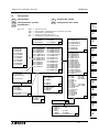
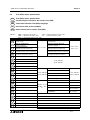
Mitsubishi FX2N Benutzerhandbuch
- Kategorie
- Vernetzung
- Typ
- Benutzerhandbuch
Dieses Handbuch ist auch geeignet für
Seite laden ...

Foreword
• This manual contains text, diagrams and explanations which will guide the reader in the correct
installation and operation of the FX
2N
and should be read and understood before attempting to install
or use the unit.
•
If in doubt at any stage during the installation of the FX
2N
always consult a professional electrical
engineer who is qualified and trained to the local and national standards. If in doubt about the
operation or use of the FX
2N
please consult the nearest Mitsubishi Electric distributor.
• This manual is subject to change without notice.
Préface
•
Le présent manuel contient des textes, des illustrations et des explications pour une installation et
une utilisation correctes des API de la série FX
2N
.
L’utilisateur doit le lire et avoir compris son contenu
avant d’installer ou d’utiliser l’appareil.
•
Si lors de l’installation des incertitudes persistent, n’hésitez pas à consulter un électricien compétent,
qualifié et formé à l’utilisation des normes électriques locales et nationales. Contactez le
représentant le plus proche de MITSUBISHI ELECTRIC si la manipulation ou l’utilisation des API de
la série FX
2N
vous pose des problèmes.
• Le présent manuel est publié sous réserve de modifications. Ces modifications peuvent être
apportées sans avis préalable.
Vorwor t
• Dieses Handbuch enthält Texte, Abbildungen und Erläuterungen zur korrekten Installation und Bedi-
enung der FX
2N
-SPS und sollte vor einer Installation oder einem Einsatz des Gerätes gelesen wer-
den. Die Inhalte müssen verstanden sein.
• Wenn während der Installation etwas unklar ist, sollten Sie auf jeden Fall eine Elektrofachkraft zu
Rate ziehen, die für die Anwendung der lokalen und nationalen elektrotechnischen Bestimmungen
qualifiziert und ausgebildet ist. Setzen Sie sich mit dem nächst erreichbaren MITSUBISHI
ELECTRIC-Händler in Verbindung, wenn bei der Bedienung oder Verwendung der FX
2N
-SPS etwas
unklar sein sollte.
• Dieses Handbuch wird vorbehaltlich etwaiger Änderungen herausgegeben. Änderungen können
ohne Hinweis vorgenommen werden.
Premessa
• Il presente manuale contiene testi, figure e spiegazioni per la corretta installazione e un corretto imp-
iego del PC FX
2N
e dovrebbe essere letto e compreso prima di installare o impiegare l’apparecchio.
• Se durante l’installazione qualcosa non fosse chiaro, dovreste consultare in ogni caso uno
specialista elettrico, qualificato e istruito sull’applicazione delle norme elettriche locali e nazionali.
Contattate il concessionario più vicino della MITSUBISHI ELECTRIC se durante le operazioni o
l’impiego del PC FX
2N
dovessero insorgere dei dubbi.
•
Il presente manuale viene pubblicato con riserva di modifiche. Ci riserviamo il diritto di apportare
modifiche al presente manuale senza alcun preavviso.
Prólogo
• Este manual contiene los textos, ilustraciones y aclaraciones para una instalación y manejo correc-
tos de las unidades PC-FX
2N
(unidades de mando de memoria programable) y deberá ser leído
antes de que se proceda a una instalación o a un empleo de la unidad. Es imprescindible que se
entienda su contenido.
• En caso de que se presente alguna duda durante la instalación, se deberá consultar en todo caso a
un electricista capacitado, que disponga de la formación correspondiente que le permita el empleo
de las disposiciones electrotécnicas locales y nacionales. Póngase en contacto con el concesionario
más próximo de la casa MITSUBISHI ELECTRIC, cuando se presente algún problema durante el
manejo o empleo de la unidad PC-FX
2N.
• Nos reservamos el derecho de efectuar en cualquier momento y sin previo aviso modificaciones o
cambios en este manual.
ENG
FRE
GER
ITL
ESP
FX2N Series Programmable Controllers
Seite laden ...
Seite laden ...
Seite laden ...

FX2N Series Programmable Controllers Standards
iv
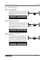
Sicherheitsrichtlinien für den Anwender und Schutzmaßnahmen für die FX
2N
-SPS
)
Dieses Handbuch enthält Informationen zur Installation und zum Einsatz der FX
2N
-SPS.
Das Handbuch wurde für geschultes und kompetentes Personal erstellt. Hierbei wird für die Qualifizierung folgende
Definition zugrunde gelegt:
a) Jeder Techniker, der Anlagen der Automatisierungstechnik unter Einbeziehung des Produktes plant, projektiert
und errichtet, sollte diesbezüglich ausreichende Kenntnisse besitzen. Hierbei sollte die Schulung und Qualifi-
zierung auch den Bereich der lokalen und nationalen Bestimmungen umfassen. Der Techniker sollte vollständige
Kenntnisse über alle Sicherheitsaspekte im Bereich der Automatisierungstechnik besitzen.
b) Jeder Inbetriebnehmer oder Service-Techniker muß zur korrekten sicheren Ausführung der Arbeitsvorgänge,
Kenntnisse im Bereich der lokalen und nationalen Bestimmungen aufweisen. Der Techniker sollte auch in der Bedi-
enung und Wartung der Geräteeinheiten geschult sein. Hierbei ist die gesamte Produktfamilie mit allen zugehöri-
gen Dokumentationen gemeint. Alle Wartungseinheiten sollten stets in Übereinstimmung mit den gängigen
Sicherheitsaspekten erfolgen.
c) Jeder, der das Produkt bedient, sollte in der sicheren Bedienung des Gerätes geschult sein. Die gängigen Sicher-
heitsaspekte sollten immer mit einbezogen werden. Der Bediener sollte sich auch mit den Dokumentationen der
übrigen Anlagenausrüstung vertraut machen.
Hinweis:
Mit dem Begriff ,übrige Anlagenausrüstung" sind alle weiteren Geräte der Automatisierungsanlage gemeint,
die in Verbindung mit dem Produkt und den zugehörigen Ha
ndbuchinformationen stehen.
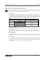
Hinweise zur der im Handbuch verwendeten Symbolik
In diesem Handbuch werden zur Hervorhebung von bestimmten Informationen verschiedene Symbole verwendet. Hiermit
erhält das Bedienpersonal alle notwendigen Hinweise zu den Sicherheits- und Schutzmaßnahmen. Bei jedem Auftreten
der Symbole muß der zugehörige Hinweis gelesen werden und die gegebene Information verstanden sein. Nachfolgend
sind alle Symbole mit einer kurzen Beschreibung der Bedeutung aufgeführt.
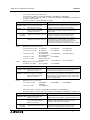
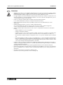
Hardware-Warnhinweise
1) Bezeichnet eine unmittelbar drohende Gefahr, die zu einem Personen- oder Sach-
schaden führen kann.
2) Bezeichnet eine möglicherweise auftretende Gefahr, die zu einem Personen- oder
Sachschaden führen kann.
3) Bezeichnet einen Punkt mit Hinweisen oder zusätzlichen Erläuterungen.
Software-Warnhinweise
4) Bezeichnet einen ausdrücklichen Warnhinweis, der bei der Programmierung auf
jeden Fall beachtet werden muß.
5) Bezeichnet einen speziellen Hinweis, der in Verbindung mit der Bedienung vom
Anwender beachtet werden sollte.
6) Bezeichnet einen Punkt mit weiteren Hinweisen oder zusätzlichen Erläuterungen.
GER
Seite laden ...
Seite laden ...

FX2N Series Programmable Controllers Standards
vii
The following FX
2N
PLC module conform to the identified standards;
Les modules suivants de la série FX2N sont conformes aux normes et critères d'homologation mentionnés.
Die folgenden Module der FX
2N
-Serie stimmen mit den aufgeführten Normen und Zulassungskriterien überein.
I seguenti moduli della serie FX2N sono conformi alle norme ed ai criteri di certificazione esposti.
Los siguientes módulos de la serie FX2N concuerdan completamente con las normas mencionadas y los criterios de
admisión.
American Bureau of Shipping (ABS)
FX
2N
- 16/32/48/64/80/128 MR-ES/UL, MT-ESS/UL
FX
2N
- 16/32/48/64/80 MR-DS, MT-DSS
FX
2N
- 16/32/48/64 MR-UA1/UL
FX
2N
- 32/48 ER-ES/UL, ET-ESS/UL, ER-DS, ET-DSS
FX
2N
- 48 ER-UA1/UL
FX
2N
- 16 EX-ES/UL, EYR-ES/UL, EYT-ESS/UL
FX
2N
-4AD FX
2N
-4DA FX
2N
-5A FX
2N
-4AD-TC FX
2N
-4AD-PT FX
2N
-232IF
FX
2N
-1HC FX
2N
-1PG-E FX
2N
-8AV-BD FX
2N
-232-BD FX
2N
-422-BD FX
2N
-485-BD
FX
2N
-CNV-IF FX
2N
-2DA FX
2N
-2AD FX
2N
-1RM-E-SET
Det Norske Veritas (DNV)
FX
2N
- 16/32/48/64/80/128 MR-ES/UL, MT-ESS/UL
FX
2N
- 16/32/48/64/80 MR-DS, MT-DSS
FX
2N
- 32/48 ER-ES/UL, ET-ESS/UL, ER-DS, ET-DSS
FX
2N
- 16 EX-ES/UL, EYR-ES/UL, EYT-ESS/UL
FX
2N
- 8 EX-ES/UL, EYR-ES/UL, EYT-ESS/UL, ER-ES/UL
FX
2N
-4AD FX
2N
-4DA FX
2N
-4AD-TC FX
2N
-4AD-PT FX
2N
-232IF FX
2N
-1HC
FX
2N
-1PG-E
Germanischer Lloyd
FX
2N
- 16/32/48/64/80/128 MR-ES/UL, MT-ESS/UL
FX
2N
- 32/48 ER-ES/UL, ET-ESS/UL
FX
2N
- 16 EX-ES/UL, EYR-ES/UL, EYT-ESS/UL
FX
2N
-4AD FX
2N
-4DA FX
2N
-5A FX
2N
-4AD-TC FX
2N
-4AD-PT FX
2N
-232IF
FX
2N
-1HC FX
2N
-1PG-E FX
2N
-2AD FX
2N
-2DA FX
0N
-3A FX
2N
-8AD
FX
2N
-8AV-BD FX
2N
-232-BD FX
2N
-422-BD FX
2N
-485-BD
Lloyds Register (Lloyds)
FX
2N
- 16/32/48/64/80/128 MR-ES/UL, MT-ESS/UL
FX
2N
- 32/48 ER-ES/UL, ET-ESS/UL
FX
2N
- 16 EX-ES/UL, EYR-ES/UL, EYT-ESS/UL
FX
2N
-4AD FX
2N
-4DA FX
2N
-5A FX
2N
-4AD-TC FX
2N
-4AD-PT FX
2N
-232IF
FX
2N
-1HC FX
2N
-1PG-E FX
2N
-2AD FX
2N
-2DA FX
0N
-3A
Registro Italiano Navale (RINA)
FX
2N
- 16/32/48/64/80/128 MR-ES/UL, MT-ESS/UL
FX
2N
- 32/48 ER-ES/UL, ET-ESS/UL
FX
2N
- 16 EX-ES/UL, EYR-ES/UL, EYT-ESS/UL
FX
2N
-4AD FX
2N
-4DA FX
2N
-5A FX
2N
-4AD-TC FX
2N
-4AD-PT FX
2N
-232IF
FX
2N
-1HC FX
2N
-1PG-E FX
2N
-8AD
BUREAU VERITAS (BV)
FX
2N
- 16/32/48/64/80/128 MR-ES/UL, MT-ESS/UL
FX
2N
- 32/48 ER-ES/UL, ET-ESS/UL
FX
2N
- 16 EX-ES/UL, EYR-ES/UL, EYT-ESS/UL
FX
2N
-4AD FX
2N
-4DA FX
2N
-4AD-TC FX
2N
-4AD-PT FX
2N
-232IF FX
2N
-1HC
FX
2N
-1PG-E
ENG
FRE
GER
ITL
ESP

FX2N Series Programmable Controllers Standards
viii
Certification of UL, cUL standards
UL, C-UL registration number E95239
Models : MELSEC FX
2N
/ FX
0N
series manufactured
FX
2N
-
MR-ES/UL FX
2N
-
MT-ESS/UL
Where
indicates:16,32,48,64,80,128
FX
2N
-
MR-DS FX
2N
-
MT-DSS
Where
indicates:16,32,48,64,80
FX
2N
-
MR-UA1/UL
Where
indicates:16,32,48,64
FX
2N
-
∆
∆
MT-E/UL
Where
∆
∆
indicates:16,32,48
FX
2N
- 32MS-E/UL FX
2N
- 48MS-E/UL
FX
2N
-
ER-ES/UL FX
2N
-
ET-ESS/UL FX
2N
-
ER-DS FX
2N
-
ET-DSS
Where
indicates:32,48
FX
2N
- 16EX-ES/UL FX
2N
- 8EX-ES/UL FX
2N
- 8EX-UA1/UL FX
2N
- 8ER-ES/UL
FX
2N
- 16EYR-ES/UL FX
2N
- 16EYT-ESS/UL FX
2N
- 16EYS FX
2N
- 8EYR-ES/UL
FX
2N
- 8EYT-ESS/UL FX
2N
- 8EYR-S-ES/UL
FX
2N
-4AD FX
2N
-4DA FX
2N
-5A FX
2N
-4AD-TC FX
2N
-4AD-PT
FX
2N
-1HC FX
2N
-1PG-E FX
2N
-2AD FX
2N
-2DA FX
0N
-3A
FX
2N
-2LC FX
2N
-64CL-M FX
2N
-16LNK-M FX
2N
-10GM FX
2N
-20GM
FX
2N
-10PG FX
2N
-8AD
Seite laden ...
Seite laden ...
Seite laden ...
Seite laden ...

1
2
3
4
5
6
7
A
B
C
D
E
1
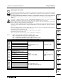
Introduction Introduction Einleitung Introduzione Introducción
2
Terminal
Layouts
Occupation
des bornes
Klemmen-
belegungen
Assegnazione
dei morsetti
Ocupaciones
de bornas
3
Installation
Notes
Installation Installation Installazione Instalación
4
Power supply
Alimentation
en tension
Spannungs-
versorgung
Alimentazione
della tensione
Alimentación
de tensión
5
Inputs Entrées Eingänge Ingressi Entradas
6
Outputs Sorties Ausgänge Uscite Salidas
7
Diagnostics
Diagnostic
d’erreurs
Fehlerdiag-
nose
Diagnostica
Diagnóstico
de fallos y
errores
A
Associated
Manuals
Autres
manuels
Weitere
Handbücher
Ulteriori
manuali
Otros
manuales
B
Discontinued
models
Modèles
abandonnés
Auslaufende
Modelle
Modelli di
cessata
produzione
Modelos que
ya no se
fabrican
C
Battery
transportation
Transport de
la batterie
Transport
der Batterie
Trasporto
della batteria
Transporte de
la batería
D
EU battery
Directive
Directive CE
relative aux piles
et accumulateurs
EU-
Batterierichtlinie
2006/66/EG
Direttiva UE
batterie
Directiva CE
sobre
pilas y
acumuladores
E
Index Index
Stichwort-
verzeichnis
Indice
analitico
Indice
alfabético
ENG
FRE GER ITL ESP
FX2N Series Programmable Controllers
Seite laden ...
Seite laden ...
Seite laden ...

FX2N Series Programmable Controllers
xvii
Inhaltsverzeichnis
Sicherheitsrichtlinien............................... iv
1. Einleitung .........................................1-1
1.1 Zubehör einer Geräteeinheit.................. 1-9
1.2 Weltweite Ausführung............................ 1-9
1.3 Gerätetypenbezeichnung .................... 1-10
1.4 Seriennummer..................................... 1-11
1.4.1 Produkt bis einschließlich Dezember
2009 ................................................ 1-11
1.4.2 Produkt ab Januar 2010.................. 1-12
1.5 Systemaufbau...................................... 1-13
1.5.1 Grundregeln zum Systemaufbau..... 1-16
2. Klemmenbelegungen .......................2-1
2.1 Grundgeräte mit Relais-Ausgängen
und DC 24V-Eingängen......................... 2-2
2.2 Grundgeräte mit Transistor-Ausgängen
transistor................................................ 2-3
2.3 Spannungsversorgte
Erweiterungsgeräte ............................... 2-4
2.4 Erweiterungsmodule.............................. 2-4
2.5 Erweiterungsmodule FX
0N
..................... 2-5
2.6 Grundgeräte mit AC 110V-Eingängen... 2-6
3. Installation ........................................3-1
3.1 Gerätebeschreibung .............................. 3-2
3.2 RUN/STOP-Kontrolle............................. 3-4
3.3 Umgebungsbedingungen ...................... 3-6
3.4 Montage der SPS .................................. 3-8
3.5 DIN-Schienen-Montage....................... 3-14
3.6 Direkte Montage .................................. 3-15
3.7 Allgemeine Hinweise ........................... 3-16
3.8 Installation der Erweiterungskarte ....... 3-17
3.9 Installation von Erweiterungen ............ 3-19
4. Elektrischer Anschluss .....................4-1
4.1 Verdrahtungshinweise ........................... 4-2
4.2 Schraubklemmenanschluss................... 4-4
4.2.1 Ausbau und Einbau des
Schnellfreigabe-Klemmenblocks....... 4-7
4.3 Spannungsversorgung ........................ 4-10
4.4 Erdung................................................. 4-15
4.5 Service-Spannungsversorgung ........... 4-16
5. Eingänge..........................................5-1
5.1 Technische Daten der Eingänge
für 24 V DC............................................ 5-1
5.1.1 Verdrahtungsbeispiel......................... 5-2
5.1.2 Eingangsschaltkreis .......................... 5-3
5.1.3 Dioden und Eingänge in Reihe
geschaltet.......................................... 5-4
5.1.4 Widerstände und Eingänge parallel
geschaltet.......................................... 5-5
5.2 Grundgeräte mit AC 110V-Eingängen... 5-6
5.2.1 Technische Daten der Eingänge für
AC 110 V ...........................................5-7
5.2.2 Verdrahtungsbeispiel.........................5-8
5.2.3 Programmierhinweise........................5-9
6. Ausgänge ........................................ 6-1
6.1 Technische Daten der
Relais-Ausgänge ................................... 6-1
6.1.1 Produktlebensdauer der
Relaiskontakte ...................................6-5
6.1.2 Beispiel einer Relais-
Ausgangsbeschaltung .......................6-8
6.1.3 Konfiguration des
Ausgangskreises .............................6-10
6.2 Technische Daten der
Triac(SSR)-Ausgänge.......................... 6-12
6.2.1 Stromstöße ......................................6-14
6.2.2 Beispiel einer Triac-
Ausgangsbeschaltung .....................6-15
6.2.3 Konfiguration des
Ausgangskreises .............................6-16
6.3 Technische Daten der Transistor-
Ausgänge............................................. 6-18
6.3.1 Ansprechzeiten................................6-20
6.3.2 Beispiel einer Transistor-
Ausgangsbeschaltung .....................6-21
6.4 Sicherheitshinweise zur Beschaltung
von Lasten ........................................... 6-22
7. Fehlerdiagnose................................ 7-1
7.1 Überprüfungen vor Betrieb .................... 7-1
7.2 Allgemeine Fehlerdiagnose ................... 7-2
7.2.1 Spannung EIN, SPS AUS..................7-2
7.2.2 BATT.V-LED leuchtet ........................7-4
7.2.3 PROG.E-LED blinkt ...........................7-6
7.2.4 CPU.E-LED leuchtet..........................7-7
7.3 Weitere Fehlerursachen ...................... 7-10
7.4 Erstellen des Programms und
Programmprüfung
[Spannungsversorgung EIN und SPS
gestoppt] .............................................. 7-13
7.5 Batterieaustausch................................ 7-16
7.6 Wartung ............................................... 7-18
7.7 Fehlermerker EIN bezeichnet einen
Fehler................................................... 7-19
7.8 Fehlerregister....................................... 7-21
7.9 Fehlercodes......................................... 7-23
7.10 Übersicht der
Applikatiosanweisungen ...................... 7-24
Appendix A:Weitere Handbücher......... A-1
Appendix B:Auslaufende Modelle ........B-1
GER
FX2N Series Programmable Controllers

FX2N Series Programmable Controllers
xviii
Appendix C:Vorsichtsmaßnahmen für
den Transport der
Batterie............................. C-3
C-1: Regulierte Produkte der FX
2N
-Serie......C-3
C-2: Richlinien für den Transport ..................C-3
Appendix D:Handhabung von Batterien
und Geräten mit eingebauten
Batterien in den
Mitgliedsstaaten der
europäischen Union ......... D-3
D-1: Vorsichtsmaßnahmen bei der
Entsorgung ............................................D-3
D-2: Vorsichtsmaßnahmen beim Export .......D-3
D-3: Regulierte Produkte der FX
2N
-Serie......D-3
Appendix E:Stichwortverzeichnis......... E-5
•Microsoft
®
und Windows
®
sind entweder eingetragene Warenzeichen oder Warenzeichen der Microsoft
Corporation in den Vereinigten Staaten von Amerika und/oder anderen Ländern.
• Die Namen der in dieser Bedienungsanleitung beschriebenen Firmen und Produkte sind eingetragene
Warenzeichen oder Warenzeichen der einzelnen Firmen.
Registrierung
Seite laden ...
Seite laden ...
Seite laden ...
Seite laden ...

Introduction 1
1-1
1
2
3
4
5
6
7
A
B
C
D
E
1. Introduction
Introduction 1.
This manual covers the hardware installation
instructions for the following programmable logic
controller (PLC) product ranges;
-FX
2N
base and extension units
-FX
2N
extension and special function blocks
Einleitung 1.
Dieses Handbuch umfaßt die Beschreibung der
Installation für die folgenden speicher-
programmierbaren Steuerungen (SPS):
-FX
2N
-Grund-und Erweiterungsgeräte
-FX
2N
-Erweiterungs- und Sondermodule
Introducción 1.
Este manual comprende la descripción de la
instalación para las siguientes unidades de mando
de memoria programable (PLC):
- Unidades base y de ampliación FX
2N
- Módulos de ampliación y especiales FX
2N
Introduction 1.
Le présent manuel comprend la description de
l’installation pour les automates programmables
(API) suivants:
- Appareils de base et appareils d’extension
FX
2N
- Modules d’extension et modules spéciaux
FX
2N
Introduzione 1.
Il presente manuale contiene la descrizione
dell’installazione per i seguenti controllori
programmabili (PLC):
- Unità FX
2N
base e di ampliamento
- Moduli FX
2N
di ampliamento e moduli speciali
ENG
GER
ESP
FRE
ITL
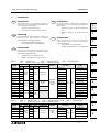
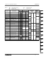
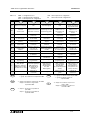
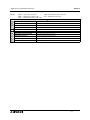
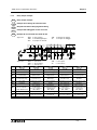
Table 1.1: ENG
☞
AC base unit FRE
☞
Appareils de base GER
☞
AC-Grundgerate
ITL
☞
Apparecchi base AC ESP
☞
Unidades base CA
MODEL
INPUTS OUTPUT TYPE
POWER
SUPPLY
DIMENSIONS
mm (inch)
MASS (WEIGHT)
kg (lbs)
QTY TYPE QTY RELAY TRANSISTOR
FX
2N
-16 8
24V DC
Sink/
Source
8
MR-
ES/UL
MT-ESS/UL
(Source)
100-240V
AC +10%
-15%, 50/
60Hz
130 (5.12)
90
(3.55)
87
(3.43)
0.60 (1.32)
FX
2N
-32 16 16 150 (5.91) 0.65 (1.43)
FX
2N
-48 24 24 182 (7.17) 0.85 (1.87)
FX
2N
-64 32 32 220 (8.67) 1.00 (2.2)
FX
2N
-80 40 40 285 (11.23) 1.20 (2.64)
FX
2N
-128 64 64 350 (13.78) 1.80 (3.96)
FX
2N
-16 8
24V DC
Sink
8
MT-E/UL
(Sink)
130 (5.12) 0.60 (1.32)
FX
2N
-32 16 16 150 (5.91) 0.65 (1.43)
FX
2N
-48 24 24 182 (7.17) 0.85 (1.87)
FX
2N
-32 16 16
MS-E/UL
(Triac output)
150 (5.91) 0.65 (1.43)
FX
2N
-48 24 24 182 (7.17) 0.85 (1.87)
FX
2N
-16 8
110V AC
8
MR-
UA1/UL
130 (5.12) 0.60 (1.32)
FX
2N
-32 16 16 182 (7.17) 0.85 (1.87)
FX
2N
-48 24 24 220 (8.67) 1.00 (2.2)
FX
2N
-64 32 32 285 (11.23) 1.20 (2.64)
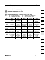
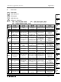
Table 1.2: ENG
☞
DC Base Units FRE
☞
Appareils de base en CC GER
☞
DC-Grundgeräte
ITL
☞
Apparecchi base DC ESP
☞
Unidades CCDC
MODEL
INPUTS OUTPUT TYPE
POWER
SUPPLY
DIMENSIONS
mm (inch)
MASS (WEIGHT)
kg (lbs)
QTY TYPE QTY RELAY TRANSISTOR
FX
2N
-16 8
24V DC
Sink/
Source
8
MR-DS
MT-DSS
(Source)
24V DC
+20%,
-30%
130 (5.12)
90
(3.55)
87
(3.43)
0.60 (1.32)
FX
2N
-32 16 16 150 (5.91) 0.65 (1.43)
FX
2N
-48 24 24 182 (7.17) 0.85 (1.87)
FX
2N
-64 32 32 220 (8.67) 1.00 (2.2)
FX
2N
-80 40 40 285 (11.23) 1.20 (2.64)
FX2N Series Programmable Controllers

FX2N Series Programmable Controllers Introduction 1
1-2
Table 1.3: ENG
☞
Powered extension units
FRE
☞
Appareils d’extension alimentés en tension
GER
☞
Spannungsversorgte Erweiterungsgeräte
ITL
☞
Apparecchi di ampliamento con alimentazione di tensione
ESP
☞
Unidades de ampliación con alimentación de tensión
MODEL
INPUTS OUTPUT TYPE
POWER
SUPPLY
DIMENSIONS
mm (inch)
MASS
(WEIGHT)
kg (lbs)
QTY TYPE QTY RELAY TRANSISTOR
FX
2N
-32 16
24V DC
Sink/Source
16
ER-
ES/UL
ET-ESS/UL
(Source)
100-240V AC
+10%, -15%,
50/60Hz
150 (5.91)
90
(3.55)
87
(3.43)
0.65 (1.43)
FX
2N
-48 24 24 182 (7.17) 0.85 (1.87)
FX
2N
-48 24 110V AC 24
ER-
UA1/UL
220 (8.67) 1.00 (2.20)
FX
2N
-48 24
24V DC
Sink/Source
24 ER-DS
ET-DSS
(Source)
24V DC
+20%, -30%
182 (7.17) 0.85 (1.87)
Table 1.4: ENG
☞
Extension blocks FRE
☞
Modules d’extension
GER
☞
Erweiterungsmodule ITL
☞
Moduli di ampliamento
ESP
☞
Módulos de ampliación
MODEL
INPUTS OUTPUTS
DIMENSIONS
mm (inch)
MASS (WEIGHT)
kg (lbs)
QTY TYPE QTY DEVICE TYPE
FX
0N
-8EX-UA1/UL
FX
2N
-8EX-UA1/UL
8
110V AC
inputs
43 (1.70)
90
(3.55)
87
(3.43)
0.20 (0.44)
FX
0N
-8EX-ES/UL
FX
2N
-8EX-ES/UL
Sink/Source
24V DC
FX
0N
-8ER-ES/UL
FX
2N
-8ER-ES/UL
44
Relay
FX
0N
-8EYR-ES/UL
FX
2N
-8EYR-ES/UL
8
FX
2N
-8EYR-S-ES/UL 40 (1.58) 0.30 (0.66)
FX
0N
-8EYT-ESS/UL
FX
2N
-8EYT-ESS/UL
8 Transistor Source 43 (1.70) 0.20 (0.44)
FX
0N
-16EX-ES/UL 16
Sink/Source
24V DC
70 (2.76) 0.30 (0.66)
FX
0N
-16EYR-ES/UL 16 Relay
FX
0N
-16EYT-ESS/UL 16 Transistor Source
FX
2N
-16EX-ES/UL 16
Sink/Source
24V DC
40 (1.58) 0.30 (0.66)
FX
2N
-16EYR-ES/UL 16 Relay
FX
2N
-16EYT-ESS/UL 16 Transistor Source

FX2N Series Programmable Controllers Introduction 1
1-3
1
2
3
4
5
6
7
A
B
C
D
E
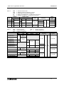
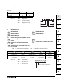
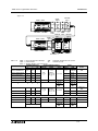
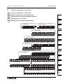
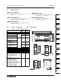
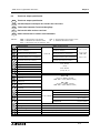
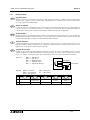
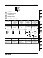
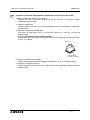
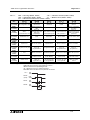
Figure 1.1: ENG
☞
Dimensioned unit FRE
☞
Dimensions
GER
☞
Abmessungen ITL
☞
Dimensioni
ESP
☞
Dimensiones
Figure 1.2: ENG
☞
Extension block dimensions
FRE
☞
Dimensions des modules d’extension
GER
☞
Abmessungen der Erweiterungsmodule
ITL
☞
Dimensioni dei moduli di ampliamento
ESP
☞
Dimensiones de los módulos de ampliación
130(5.12")
350(13.78")
90(3.55")
87(3.43")
DIN rail:
35mm(1.37")
UNITS: mm(inches)
27.3(1.08")
27.3(1.08")
87(3.43")
DIN rail:
35mm(1.37")
UNITS: mm(inches)
40(1.58")
70(2.76")
90(3.55")
27.3(1.08")
27.3(1.08")

FX2N Series Programmable Controllers Introduction 1
1-4
*1 This value is current consumption of FX2N-
422-BD only. The user must consider the
current draw of other equipment cnnected via
the board.
Please see the appropriate manual for current
consumption values.
*2 The communication adapter needs to connect
via FX
2N
-CNV-BD to FX
2N
Series PLC.
*1 Dies ist nur die Stromaufnahme des FX2N-
422-BD. Berücksichtigen Sie auch die
Stromaufnahme der angeschlossenen
Geräte.
Nähere Hinweise zur Stromaufnahme finden
Sie in den Handbüchern zu diesen Geräten.
*2 Das Modul wird über einen Kommunikations-
adapter FX
2N
-CNV-BD mit dem FX
2N
-
Grundgerät verbunden.
*1 Esto es sólo la alimentación de corriente del
FX2N-422-BD. Considere también la
alimentación de corriente de los aparatos
conectados. Mayores informaciones acerca
de la alimentación de corriente pueden
encontrarse en los manuales de estos
aparatos.
*2 El módulo es conectado a través del
adaptador de comunicación FX2N-CNV-BD
con el aparato base FX2N
*1 Représente seulement la consommation du
FX2N-422-BD. Prenez également en
considération la consommation des appareils
raccordés. Vous trouverez de plus amples
informations sur la consommation dans les
manuels de ces appareils.
*2 Le module est raccordé à l'appareil de base
FX2N via un adaptateur de communication
FX2N-CNV-BD.
*1 Si tratta solo dell'assorbimento di corrente
della serie FX2N-422-BD. Si prega di
prendere in considerazione anche
l'assorbimento di corrente degli strumenti
collegati. Ulteriori informazioni riguardanti
l'assorbimento di corrente sono reperibili nei
manuali degli strumenti.
*2 Il modulo è collegato allo strumento base
FX2N mediante adattatore di comunicazione
FX2N-CNV-BD.
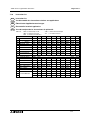
Table 1.5: ENG
☞
Expansion board and communication adapter
FRE
☞
Adaptateur d'interface, adaptateur d'allocation de valeur de consigne analogique et modules de
communication
GER
☞
Schnittstellenadapter, analoger Sollwertvorgabe-Adapter und Kommunikationsmodule
ITL
☞
Adattatore di interfaccia, adattatore analogico dei valori reali programmati e moduli di comunicazione
ESP
☞
Adaptador de interfaz, adaptador análogo de indicación de valor nominal y módulos de comunicación
MODEL DESCRIPTION
NUMBER Current Consumed
DEIMENSIONS
mm (inch)
MASS (WEIGHT)
kg (lbs)
I O
Internal
5V DC
External
24V DC
FX
2N
-232-BD RS-232C communication interface - 0 - 20mA -
Mounts directly into
top of PLC
Mounts directly
into top of PLC
FX
2N
-422-BD RS-422 communication interface - 0 -
60mA
*1
-
FX
2N
-485-BD RS-485 communication interface - 0 - 60mA -
FX
2N
-CNV-BD
Communication adapter
connection interface
-0- - -
FX
2N
-8AV-BD Analog potentiometer - 0 - 20mA -
FX
2NC
-232ADP
*2
RS-232C communication adapter - 0 - 100mA -
19.1
(0.76)
90
(3.55)
85
(3.35)
0.1 (0.22)
FX
0N
-232ADP
*2
RS-232C communication adapter - 0 - 200mA -
43
(1.70)
68
(2.68)
FX
2NC
-485ADP
*2
RS-485 communication adapter - 0 - 150mA -
19.1
(0.76)
78
(3.08)
FX
0N
-485ADP
*2
RS-485 communication adapter - 0 - 30mA 50mA
43
(1.70)
87
(3.43)
0.3 (0.66)
ENG
GER
ESP
FRE
ITL

FX2N Series Programmable Controllers Introduction 1
1-5
1
2
3
4
5
6
7
A
B
C
D
E
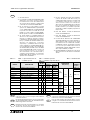
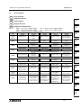
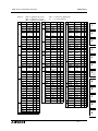
Table 1.6: ENG
☞
Special function blocks FRE
☞
Modules spéciaux
GER
☞
Sondermodule ITL
☞
Moduli speciali
ESP
☞
Módulos especiales blocks
MODEL DESCRIPTION
NUMBER
OF I/O
Current Consumed
DIMENSIONS
mm
(inches)
MASS
(WEIGHT)
kg (lbs)
I O
Internal
5V DC
External
24V DC
FX
0N
-3A Analog/Digital converter - 8 - 30mA
90mA
*1
43
(1.70)
90
(3.55)
87
(3.43)
0.20 (0.44)FX
2N
-2AD Analog to digital converter - 8 - 20mA
50mA
*1
FX
2N
-2DA Digital to analog converter - 8 - 30mA
85mA
*1
FX
2N
-4DA Digital to analog converter - 8 - 30mA 200mA
55
(2.17)
0.30 (0.66)
FX
2N
-4AD Analog to digital converter - 8 - 30mA 55mA
FX
2N
-5A Analog/Digital converter - 8 - 70mA 90mA
FX
2N
-8AD Analog to digital converter - 8 - 50mA 80mA
75
(2.96)
FX
2N
-4AD-PT PT100 probe interface - 8 - 30mA 50mA
55
(2.17)
FX
2N
-4AD-TC Thermo-couple interface - 8 - 30mA 50mA
FX
2N
-2LC Temperature Control Block - 8 - 70mA 55mA
FX
2N
-1HC High speed counter - 8 - 90mA NA
55
(2.17)
90
(3.55)
87
(3.43)
0.30 (0.66)
FX
2N
-1PG-E Pulse output, Position control - 8 - 55mA 40mA
43
(1.70)
0.20 (0.44)
FX
2N
-10PG Pulse output, Position control - 8 - 120mA
*2
FX
2N
-10GM Positioning Controller (1 axis) - 8 -
NA NA
60
(2.37)
0.30 (0.66)
FX
2N
-20GM Positioning Controller (2 axis) - 8 -
86
(3.39)
0.40 (0.88)
FX
2N
-1RM-E-
SET
Programmable Cam Switch - 8 - NA 250mA
55
(2.17)
111
(4.38)
97
(3.82)
0.50 (1.10)
FX
2N
-232IF RS232 Interface block - 8 - 40mA 80mA
90
(3.55)
87
(3.43)
0.30 (0.66)
FX
2N
-32CCL CC-Link Slave Interface - 8 - 130mA 50mA
43
(1.70)
0.20 (0.44)
FX
2N
-16CCL-M
*3
CC-Link Master module
*4
8
*4
NA 150mA
85
(3.35)
0.40 (0.88)
FX
2N
-64CL-M CC-Link/LT Interface block
*6
190mA
25mA
*7
43
(1.70)
0.30 (0.66)
FX
2N
-16LNK-M I/O Link Remote Master module
*5
200mA 90mA 0.30 (0.66)
FX
2N
-32ASI-M
*3
ASI Master Module
*8
8
*8
150mA
*9
55
(2.17)
0.20 (0.44)
FX
0N
-16NT Net-mini interface 8 8 20mA 60mA
43
(1.70)
Seite laden ...

FX2N Series Programmable Controllers Introduction 1
1-7
1
2
3
4
5
6
7
A
B
C
D
E
*1 Interne 24 V DC
*2 Die Ein- und Ausgänge des FX
2N
-10PG
müssen von extern mit Spannung versorgt
werden. Angaben zur Stromaufnahme der
Ein- und Ausgänge enthält das Handbuch
zum FX
2N
-10PG.
*3 In einer SPS der FX
2N
-Serie kann kein FX
2N
-
32ASI-M gemeinsam mit einem FX
2N
-16CCL-
M betrieben werden. Ein FX
2N
-32ASI-M kann
nicht an SPS der FX
2N
-Serie angeschlossen
werden, in der ein FX
2N
-16CCL-M verwendet
wird. Es kann nur ein FX
2N
-32ASI-M
angeschlossen werden.
*4 Es kann die max. Anzahl der E/A-Adressen
pro System ausgenutzt werden, solange die
folgende Bedingung erfüllt wird:
(Anzahl E/A des Grundgeräts) + (Anzahl E/A
von Erweiterungsgeräten und Sonder-
modulen) + (Anzahl Adr., die durch FX
2N
-
16CCL-M belegt werden: 8) + (32 x Anzahl
der dezentralen E/A-Module)
≤
256
Bei Verwendung von mehreren FX
2N
-16CCL-
M kann das 1. Master-Modul mit „dezentralen
I/O-Modulen“ und „dezentralen Geräten“
verbunden werden, die weiteren FX
2N
-
16CCL-M aber nur mit „dezentralen Geräten“.
*5 Der Wert hängt von der Einstellung der
Schalter ab (16, 32, 48, 64, 96 oder 128 Adr.).
Die Anzahl der installierbaren Master-Module
wird jedoch durch den Adressbereich der
CPU begrenzt. Die Summe der E/A-Adressen
des Grundgeräts, von Erweiterungsgeräten,
Master-Modulen und Sondermodulen
(belegen 8 Ein- und Ausgänge) darf nicht
größer als 256 sein.
*6 Einzelheiten siehe das Benutzerhandbuch
des FX2N-64CL-M.
*7 Einzelheiten siehe das Benutzerhandbuch
des FX2N-64CL-M.
*8 Die Summe der E/A-Adressen des FX
2N
-
32ASI-M und der CPU der SPS darf 256 nicht
überschreiten. Dadurch besteht eine
Beschränkung bei der Anzahl der Einheiten
(Anzahl der Slaves), die angeschlossen und
von der CPU erkannt werden können.
Belegte E/A-Adressen: Jedes AS-i-Slave-
Modul belegt 4 Ein- und 4 Ausgänge.
*9 Das FX
2N
-32ASI-M wird von einem externen
AS-I-Netzteil mit Spannung versorgt und
nimmt 70 mA auf.
*1 Corrente 24 V DC interna
*2 Le entrate e le uscite del FX2N-10PG devono
essere munite di tensione dall'esterno. Le
informazioni sulle entrate e le uscite sono
contenute nel manuale FX2N-10PG.
*3 In un PLC della serie FX2N non si può
mettere in esercizio nessun FX2N-32ASI-M
insieme al FX2N-16CCL-M . Ad un PLC della
serie FX2N non si può collegare un modulo
FX2N-32ASI-M, nel quale si utilizza un FX2N-
16CCL-M . Si può collegare solo un FX2N-
32ASI-M .
*4 Si può utilizzare il numero massimo di
indirizzi e/u per sistema, se si rispettano le
seguenti condizioni: (Numero di E/U dello
strumento base) + (Numero di E/U degli
strumenti di ampliamento e dei moduli
speciali) + (Numero di indirizzi, occupati dal
FX2N-16CCL-M: 8) + (32 x numero dei
moduli decentrali E/U)
≤
256
Utilizzando diversi FX2N-16CCL-M, si può
collegare il primo modulo master ai moduli
"decentrali I/O" e agli strumenti "decentrali" ,
gli altri FX2N-16CCL-M però, solo agli
strumenti "decentrali"
*5 Il valore dipende dalla programmazione
dell'interruttore (16, 32, 48, 64, 96 o 128
indirizzi). Il numero dei moduli master che si
possono installare è limitato dal settore
indirizzi del CPU. La somma degli indirizzi E/
U- dello strumento base, delle unità di
ampliamento, dei moduli master e dei moduli
speciali (occupano 8 entrate e uscite) non
deve essere superiore a 256.
*6 Per ulteriori informazioni, far riferimento al
manuale d’istruzioni per l’uso di FX2N-64CL-
M.
*7 Per ulteriori informazioni, far riferimento al
manuale d’istruzioni per l’uso di FX2N-64CL-
M.
*8 La somma degli indirizzi I/U del FX2N-32ASI-
M e del CPU del PLC non deve essere
superiore a 256 indirizzi: In tal modo si
verifica una limitazione del numero di unità
(numero di slave), che possono essere
collegati e riconosciuti dal CPU. Indirizzi I/U-
occupati: Ciascun modulo AS-i-Slave-
occupa 4 entrate e 4 uscite.
*9 Il modulo FX2N-32ASI-M è alimentato dalla
rete esterna AS-I con tensione e assorbe 70
mA.
GER
ITL
Seite laden ...

FX2N Series Programmable Controllers Introduction 1
1-9
1
2
3
4
5
6
7
A
B
C
D
E
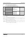
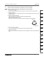
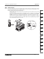
1.1 Unit Accessories
Unit Accessories 1.1
Each powered extension unit comes with: 1 I/O label
kit and a 55mm (2.17 inch) extension cables.
Each extension and special function block comes
with an I/O label kit.
Zubehör einer Geräteeinheit 1.1
Lieferumfang eines spannungsversorgten Erweite-
rungsgerätes: 1 E-/A-Aufklebersatz und die beiden
Erweiterungskabel mit 55 mm Länge. Jedes
Erweiterungs- und Sondermodul wird mit einem E-/A-
Aufklebersatz ausgeliefert.
Accesorios de una unidad de
producción 1.1
Volumen de suministro de una unidad de ampliación
con alimentación de tensión: 1 juego de etiquetas
autoadhesivas E/S y los dos cables de ampliación
con una longitud de 55 mm. Cada módulo de
ampliación y módulo especial es suministrado con un
juego de etiquetas autoadhesivas de E/S.
Accessoires d’un appareil 1.1
Etendue de la fourniture d’un appareil d’extension
alimenté en tension: 1 jeu d’auto-collants E/S et le
câble d’extension de 55 mm de long.
Chaque module d’extension et module spécial est
livré avec un jeu d’autocollants E/S.
Accessori di un apparecchio 1.1
Volume di fornitura di un apparecchio di ampliamento
con alimentazione di tensione: no.1 set di adesivi I/O
e i due cavi di ampliamento di 55 mm di lunghezza.
Ogni modulo di ampliamento e ogni modulo speciale
viene fornito con un set di adesivi I/O.
1.2 World Specification
World Specification 1.2
Weltweite Ausführung. 1.2
Modelo internacional 1.2
Version internationale 1.2
Esecuzione internazionale. 1.2
ENG
GER
ESP
FRE
ITL
ENG
GER
ESP
FRE
ITL
Table 1.8: ENG
☞
World/Japanese Spec. FRE
☞
Version internationale /japonaise.
GER
☞
Weltweite/japanische Ausf. ITL
☞
Versione internazionale /giapponese
ESP
☞
Modelo internacional /modelo para el Japón
ITEM
Input S/S
terminal
Sink/Source
ONLY WORLD
SPEC. PLC’s have
this terminal
-ve S/S
connection = source
+ve S/S
connection = sink
Tous les appareils
en version
internationale
possèdent les
bornes suivantes:
Borne (- S/S)=
source (émetteur),
Borne (+ S/S)=
sink (récepteur)
Alle Geräte der
weltweiten Ausf.
haben die
Klemmen:
(- S/S) Klemme =
Source,
(+ S/S) Klemme =
Sink
Tutti gli
apparecchi
della versione
internazionale
hanno i morsetti:
morsetto (- S/S)=
source,
morsetto (+ S/S) =
sink
Todas las unidades
del modelo
internacional
disponen de las
bornas:
Borna (- S/S) =
Source,
Borna (+ S/S) =
Sink
Outputs
Transistor
Japanese models
are ALWAYS SINK.
World spec
models depend on
the PLC selection
Tous les appareils
de type japonais
sont équipés d’un
raccord SINK. Pour la
version
internationale, cela
dépend des types
d’appareils.
Alle japanischen
Typen mit SINK-
Anschluß. Bei der
weltweiten Ausf.
vom Gerätetyp
abhängig.
Tutti i modelli
giapponesi hanno il
collegamento
SINK.Nella
versione
internazionale ciò
dipende dal modello.
Todos los modelos
para el Japón
disponen de
unaconexión SINK.
En el modelo
internacional en
función del tipo de
unidad.
ENG FRE
GER ITL
ESP

FX2N Series Programmable Controllers Introduction 1
1-10
1.3 Model name
Model name 1.3
Gerätetypenbezeichnung 1.3
Designacion del tipo de unidad 1.3
Designation des types d'appareils. 1.3
Designazione dei modelli. 1.3
ENG
GER
ESP
FRE
ITL
Table 1.9: ENG
☞
Model table FRE
☞
Description des types
GER
☞
Typenbeschreibung ITL
☞
Descrizione dei modelli
ESP
☞
Descripción del tipo
REF
A)
PLC type, FX,
FX
0N
, FX
2N
Série d’API: FX,
FX
0N
, FX
2N
SPS-Serie: FX,
FX
0N
,FX
2N
Serie di PLC: FX,
FX
0N
, FX
2N
Serie PLC: FX,
FX
0N
, FX
2N
B)
Total number of I/O
channels
FX
2N
-64= 64ch.
FX
2N
-16EX = 16ch.
Nombre d’entrées
et de sorties
FX
2N
-64 = 64 Ka.
FX
2N
-16EX = 16 Ka.
Anzahl der Ein-/
Ausgänge
FX
2N
-64 = 64
FX
2N
-16EX = 16
Numero di
ingressi/uscite
FX
2N
-64 = 64 Ka.
FX
2N
-16EX = 16 Ka.
Número de las
entradas/salidas
FX
2N
-64 = 64 Ca.
FX
2N
-16EX = 16 Ca.
C)
Unit type Types d’appareils Gerätetypen Modelli Tipos de unidad
M MPU-base unit Appareil de base Grundgerät Apparecchio base Unidad base
E
Powered extension
unit
Appareils d’extension
alimentés en tension
Spannungsversorgtes
Erweiterungsgerät
Apparecchio di
ampliamento con
alimentazione di
tensione
Unidad de ampliación
con alimentación de
tensión
EX
Extension
block, input
Module d’extension,
entrées
Erweiterungsmodul,
Eingänge
Modulo di
ampliamento, ingressi
Módulo de
ampliación, entradas
EY
Extension
block, output
Module
d’extension, sorties
Erweiterungsmodul,
Ausgänge
Modulo di
ampliamento, uscite
Módulo de
ampliación, salidas
D)
Output type Technologie de sortie
Ausgangs-
technologie
Tecnologia di uscita Tecnología de salida
R Relay Relais Relais Relè Relé
S Triac (SSR) Triac (SSR) Triac (SSR) Triac (SSR) Triac (SSR)
T Transistor Transistor Transistor Transistor Transistor
E)
Features Variantes de modèles Modellvarianten Varianti
Variantes de
modelos
omit
or
E*
AC, Japanese spec.
CA, version
japonaise
AC, japanische
Ausf.
AC, versione
giapponese
CA, modelo para el
Japón
D
24V DC
Japanese spec.
24V CC, version
japonaise
DC 24V, japanische
Ausf.
24V DC, versione
giapponese
24V CC, modelo
para el Japón
DS*
24V DC
World spec.
CC, Version
internationale
DC, weltweite
Ausf.
DC, Versione
internazionale
CC, Modelo
internacional
DS
S
24V DC
World spec., DC
source transistor
(See Table 1.9)
CC, Version
internationale, CC
transistor source
(Cf. le Tableau 1.9)
DC, weltweite
Ausf., DC Source-
Transistor
(siehe Tabelle 1.9)
DC, Versione
internazionale, DC
transistor source
(vedi Tabella 1.9)
CC, Modelo
internacional, CC
transistor Source
(Véase Tabla 1.9)
ES
AC Power Supply
World spec., Relay
CA, Version
internationale, Relais
AC, weltweite
Ausf., Relais
AC, Versione
internazionale,Relè
CA, Modelo
internacional, Relé
ES
S
AC Power Supply
World spec., DC
source transistor
CA, Version
internationale, CC
transistor source
AC, weltweite
Ausf., DC Source-
Transistor
AC, Versione
internazionale, DC
transistor source
CA, Modelo
internacional, CC
transistor Source
UA
1
AC Power Supply,
AC inputs
Tension de
service CA, Tension
d’entreé CA
AC -Service-
Spannung,
AC Eingangs-
spannung
Tensione di servizio
AC,
Tensione di
ingresso AC
Tensión de
servicio CA,
Tensión de
entrada CA
F)
UL*
CE, UL registered
product
Produit agréé par
l’UL, CE
CE, UL-
registriertes Produkt
Prodotto registrato
CE, UL
Producto registrado
según CE, UL
ENG FRE GER
ITL
ESP

FX2N Series Programmable Controllers Introduction 1
1-11
1
2
3
4
5
6
7
A
B
C
D
E
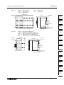
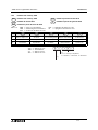
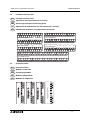
Figure 1.3: ENG
☞
Model name
FRE
☞
Désignation des types d’appareils.
GER
☞
Typenbezeichnung
ITL
☞
Modello.
ESP
☞
Designación del tipo
1.4 Serial numbers
Serial number 1.4
Seriennummer 1.4
Número de serie 1.4
Numéro de serie 1.4
Numero di serie 1.4
1.4.1 Product during December, 2009 or earlier
Product during December, 2009 or
earlier 1.4.1
Produkt bis einschließlich Dezember
2009 1.4.1
Producto hasta diciembre del 2009, este
mes incluido 1.4.1
Produit en Décembre 2009 ou avant 1.4.1
Prodotto fino a dicembre 2009 incluso1.4.1
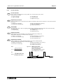
Figure 1.4: ENG
☞
Serial number
FRE
☞
Numéro de série
GER
☞
Seriennummer
ITL
☞
Numero di serie
ESP
☞
Número de serie
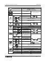
Table 1.10:
Model CE UL
FX
2N
-**MR-DS, **MT-DSS
✔✔
FX
2N
-**M*-E/UL
✘✔
FX
2N
-16EYS
✘✔
A )
B )
C )
D )
E )
F )
F X
2 N
-
1 6 M R E S / U L
-
ENG
GER
ESP
FRE
ITL
ENG
GER
ESP
FRE
ITL
Table 1.11: ENG
☞
Notes on serial numbers FRE
☞
Explication du numéro de série
GER
☞
Erläuterung der Seriennummer ITL
☞
Spiegazione del numero di serie
ESP
☞
Aclaración del número de serie
REF
1
Last digit of year
Dernier chiffre de
l’année
Letzte Ziffer des
Herstellungsjahrs
Ultima cifra dell'anno di
produzione
Última cifra del año de
fabricación
2
Production month Mois de production Produktionsmonat Mese di produzione Mes de producción
3
Production
serial number
Numéro de série de
la production
Seriennummer der
Produktion
Numero di serie
della produzione
Número de serie de
la producción
ENG FRE
GER ITL
ESP
1)
9Z000
3)
1
2)
1 to 9 = January to September,
X = October, Y = November, Z = Decembe
r

FX2N Series Programmable Controllers Introduction 1
1-12
1.4.2 Product from January, 2010
Product from January, 2010 1.4.2
Produkt ab Januar 2010 1.4.2
Producto a partir de enero de 2010 1.4.2
Produit à partir de Janvier 2010 1.4.2
Prodotto a partire da gennaio 2010 1.4.2
Figure 1.5: ENG
☞
Serial number
FRE
☞
Numéro de série
GER
☞
Seriennummer
ITL
☞
Numero di serie
ESP
☞
Número de serie
ENG
GER
ESP
FRE
ITL
Table 1.12: ENG
☞
Notes on serial numbers FRE
☞
Explication du numéro de série
GER
☞
Erläuterung der Seriennummer ITL
☞
Spiegazione del numero di serie
ESP
☞
Aclaración del número de serie
REF
1
Last two digit of year
Deux derniers chiffres
de l’année
Letzten beiden Ziffern
des Herstellungsjahres
Le ultime due cifre
dell'anno di produzione
Últimas cifras del año
de fabricación
2
Production month Mois de production Produktionsmonat Mese di produzione Mes de producción
3
Production
serial number
Numéro de série de
la production
Seriennummer der
Produktion
Numero di serie
della produzione
Número de serie de
la producción
ENG FRE
GER ITL
ESP
1)
0
1
1000
3)
1
2)
1 to 9 = January to September,
X = October, Y = November, Z = December

FX2N Series Programmable Controllers Introduction 1
1-13
1
2
3
4
5
6
7
A
B
C
D
E
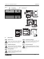
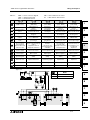
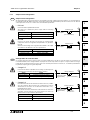
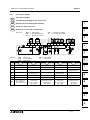
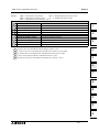
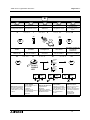
1.5 Configuration
Configuration 1.5
Configuration du système 1.5
Systemaufbau 1.5
Struttura del sistema 1.5
Configuración del sistema 1.5
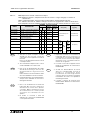
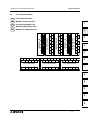
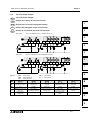
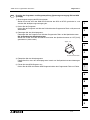
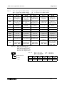
Figure 1.6: ENG
☞
Schematic system
FRE
☞
Représentation schématique de la construction du système
GER
☞
Schematischer Systemaufbau
ITL
☞
Struttura schematica del sistema
ESP
☞
Configuración esquemática del sistema
ENG
FRE
GER
ITL
ESP
,
FX
2N
-8AV-BD
FX
2N
-232-BD
FX
2N
-485-BD
FX
2N
-422-BD
G
GX Developer
FX-PCS/WIN-E
GX IEC Developer
I
RS-422/RS-232C Converter
FX-232AW
FX-232AWC
FX-232AWC-H
RS-422/USB Converter
FX-USB-AW
J
FX-30P
FX-20P-E-SET0
FX-20P-E
FX-10P-E
K
GOT-F900 Series
GOT-A900 Series
L
FX-50DU-TKS-E
FX-40DU-TK-ES
FX-40DU-ES
FX-30DU-E
L'
FX-EEPROM-4
FX-EEPROM-8
FX-EEPROM-16
H
FX-EPROM-8
FX-RAM-8
FX
2N
-ROM-E1
FX
2N
-16MR-ES/UL
FX
2N
-32MR-ES/UL
FX
2N
-48MR-ES/UL
FX
2N
-64MR-ES/UL
FX
2N
-80MR-ES/UL
FX
2N
-128MR-ES/UL
A
FX
2N
-16MT-ESS/UL
FX
2N
-32MT-ESS/UL
FX
2N
-48MT-ESS/UL
FX
2N
-64MT-ESS/UL
FX
2N
-80MT-ESS/UL
FX
2N
-128MT-ESS/UL
FX
2N
-32ER-ES/UL
FX
2N
-48ER-ES/UL
B
FX
0N
-8EX-ES/UL
FX
2N
-8EX-ES/UL
FX
0N
-16EX-ES/UL
FX
2N
-16EX-ES/UL
FX
0N
-8EX-UA1/UL
FX
2N
-8EX-UA1/UL
FX
0N
-8ER-ES/UL
FX
2N
-8ER-ES/UL
FX
0N
-8EYR-ES/UL
FX
2N
-8EYR-ES/UL
FX
2N
-8EYR-S-ES/UL
FX
0N
-16EYR-ES/UL
FX
2N
-16EYR-ES/UL
FX
0N
-8EYT-ESS/UL
FX
2N
-8EYT-ESS/UL
FX
0N
-16EYT-ESS/UL
FX
2N
-16EYT-ESS/UL
FX
2N
-16EYS
C
FX
0N
-3A
FX
2N
-2AD
FX
2N
-4AD
FX
2N
-8AD
FX
2N
-4AD-TC
FX
2N
-2LC
FX
2N
-1HC
FX
2N
-1PG-E
FX
2N
-10GM
FX
2N
-1RM-E-SET
FX
2N
-232IF
FX
2N
-16CCL-M
FX
2N
-32CCL
FX
2N
-64CL-M
FX
2N
-16LNK-M
FX
2N
-32ASI-M
FX
0N
-16NT
D
FX
2N
-5A
FX
2N
-2DA
FX
2N
-4DA
FX
2N
-4AD-PT
FX
2N
-10PG
FX
2N
-20GM
FX
2N
-CNV-IF
E
➀
➀
''
➀
'
➂
➁
➃
FX-4AD
FX-2AD-PT
FX-4AD-TC
FX-1HC
FX-1PG-E
FX-10GM
FX-16NP/NT
F
FX-2DA
FX-4DA
➃
FX
2N
-CNV-BD +
FX
0N
-232ADP
FX
2N
-CNV-BD +
FX
2NC
-485ADP
FX-PCS/AT-EE
FX
2N
-32ET-ESS/UL
FX
2N
-48ET-ESS/UL
FX
2N
-48ER-UA1/UL
FX
2N
-48ER-DS
FX
2N
-48ET-DSS
FX-1GM
FX-20GM
FX-16NP/NT-33
FX-10DM-E
FX-10DU-E
FX
2N
-16MR-UA1/UL
FX
2N
-32MR-UA1/UL
FX
2N
-48MR-UA1/UL
FX
2N
-64MR-UA1/UL
FX
2N
-16MR-DS
FX
2N
-32MR-DS
FX
2N
-48MR-DS
FX
2N
-64MR-DS
FX
2N
-16MT-E/UL
FX
2N
-32MT-E/UL
FX
2N
-48MT-E/UL
FX
2N
-16MT-DSS
FX
2N
-32MT-DSS
FX
2N
-48MT-DSS
FX
2N
-64MT-DSS
FX
2N
-80MT-DSS
FX
2N
-32MS-E/UL
FX
2N
-48MS-E/UL
FX
2N
-CNV-BD +
FX
2NC
-232ADP
FX
2N
-CNV-BD +
FX
0N
-485ADP
FX-20DU-E

FX2N Series Programmable Controllers Introduction 1
1-14
*1 F group : discontinued since June 2002
L' group : discontinued since September 2002
*1 Gruppe F:Produktion eingestellt im Juni 2002
Gruppe L':Produktion eingestellt im
September 2002
*1 Grupo F: Producción suspendida en
junio 2002
Grupo L': Producción suspendida en
septiembre 2002
*1 F group: Production arrêtée en juin 2002
L' group: Production arrêtée en
septembre2002
*2 Gruppo F: Produzione sospesa nel
giugno 2002
Gruppo L': Produzione sospesa nel
settembre 2002
Table 1.13: ENG
☞
Configuration notes FRE
☞
Description de la configuration
GER
☞
Konfigurationsbeschreibung ITL
☞
Descrizione della configurazione
ESP
☞
Descripción de la configuración
REF
A
MPU - base unit
(Main Processing Unit)
Appareils de base
API
SPS-Grundgerät
Apparecchio base
PLC
Unidad base de
mando de memoria
programable (PLC)
B
Powered
extension unit
Appareils d’extension
alimentés en tension
Spannungsversorgte
Erweiterungsgeräte
Apparecchi di
ampliamento con
alimentazione di
tensione
Unidades de
ampliación con
alimentación de
tensión
C
Extension block
Modules
d’extension
Erweiterungsmodule
Moduli di
ampliamento
Módulos de
ampliación
D
Special function block
for FX
2N
Series
Modules spéciaux de
la série FX2N
Sondermodule der
FX
2N
-Serie
Moduli speciali della
serie FX2N
Módulos especiales de
la serie FX2N
E
Bus conversion
interface
Adaptateur de
communication
Kommunikations-
adapter
Adattatore di
comunicazione
Adaptador de
comunicación
F
*1
Special function block
for FX Series
Modules spéciaux de
la série FX
Sondermodule der
FX-Serie
Moduli speciali della
serie FX
Módulos especiales de
la serie FX
G
Expansion board and
communication
adapters
Adaptateur d'interface
et modules de
communication
Schnittstellenadapter
und Kommunikations-
module
Adattatore di
interfaccia e adattatore
di comunicazione
Adaptador de interfaz y
módulos de
comunicación
H
Memory cassette Cassette-mémoire Speicherkassette Cassetta di memoria Casete de memoria
I
Computer software
Logiciel
d’ordinateur
Computer-Software
Software per il
computer
Software de
ordenadorr
J
Computer interface Interface d’ordinateur
Computer-
Schnittstelle
Interfaccia per il
computer
Interfaz de ordendor
K
Dedicated
programming
Appareils de
programmation
Programmiergeräte
Unità di
programmazione
Unidades de
programaciónsion
L
GOT (Graphic
Operation Terminal)
/DM (Display module)
/DU (Data access Unit)
GOT (Appareil de
commande graphique)
DM (Affichages)
DU (Appareils de
commande de
données)
GOT (Grafische
Bediengeräte)
DM (Anzeigen)
DU (Text-
Bediengeräte)
GOT (strumenti
operativi grafici)
DM (Display)
DU (strumenti operativi
di testo)
GOT (aparatos de
manejo gráfico)
DM (Indicadores)
DU (aparatos de
manejo de texto)
L'
*1
Data access units
Appareils de
commande
Bediengeräte
Apparecchi video
grafici
Unidades de
mandoación
ENG FRE
GER ITL
ESP
ENG
GER
ESP
FRE
ITL

FX2N Series Programmable Controllers Introduction 1
1-15
1
2
3
4
5
6
7
A
B
C
D
E
Note
When connecting peripheral equipment
(programming tool or GOT [direct connection to
CPU]) via the FX
2N
-232-BD, FX
2N
-422-BD, FX
2NC
-
232ADP or the FX
0N
-232ADP, FX
2N
main unit should
be the following setting condition.
- Set the special data register for the communication
format setting of the channel connecting the
peripheral equipment (D8120) to K0.
- Set the communication parameter to "Not set".
Hinweis
Beim Anschließen eines Peripheriegeräts
(Programmiergerät oder GOT [direkter Anschluss an
die Zentraleinheit]) über FX
2N
-232-BD, FX
2N
-422-BD,
FX
2NC
-232ADP oder FX
0N
-232ADP sollte die FX
2N
-
Haupteinheit den folgenden Einstellungszustand
aufweisen.
- Stellen Sie das Spezialdatenregister für die
Kommunikationsformateinstellung des Kanals, an
den das Peripheriegerät (D8120) angeschlossen
ist, auf K0 ein.
- Stellen Sie den Kommunikationsparameter auf
„Nicht eingestellt“ ein.
Nota
Lors du raccordement d’un équipement périphérique
(outil de programmation ou GOT [raccordement
direct à CPU] via le FX
2N
-232-BD, FX
2N
-422-BD,
FX
2NC
-232ADP ou FX
0N
-232ADP, l’unité principale
FX
2N
devra se trouver dans la condition de réglage
suivante.
- Régler l’enregistreur de données spécial pour le
réglage d’une disposition de communication du
canal raccordant l’équipement périphérique
(D8120) à K0.
- Régler le paramètre de communication sur "Not
set".
Nota
Cuando vaya a conectar el equipo periférico
(herramienta de programación o GOT [conexión
directa al CPU]) vía el FX
2N
-232-BD, FX
2N
-422-BD,
FX
2NC
-232ADP ó el FX
0N
-232ADP, la unidad
principal del FX
2N
deberá estar en la siguiente
condición de ajuste.
- Ajuste el registro de los datos especiales para el
formato de comunicación del canal de conexión del
equipo periférico (D8120) a K0.
- Ajuste el parámetro de comunicación como “Not
set”.
Table 1.14: ENG
☞
Connection ports FRE
☞
Interfaces
GER
☞
Schnittstellen ITL
☞
Interfaccia
ESP
☞
Interfaces
Connection to Connexion avec Verbindung mit Allacciamento con Conexión con
➀
Left hand side port
Raccordement de
bus gauche
linker Bus-Anschluss
Collegamento BUS
sinistro
Conexión de bus
izquierda
➀
'
Left hand side port
+FX
2N
-422-BD
Raccordement de
bus gauche
+FX
2N
-422-BD
linker Bus-Anschluss
+FX
2N
-422-BD
Collegamento BUS
sinistro
+FX
2N
-422-BD
Conexión de bus
izquierda
+FX
2N
-422-BD
➀
''
Left hand side port
+FX
2N
-232-BD
or
Left hand side port
+ FX
2N
-CNV-BD
+FX
2NC
-232ADP
or
Left hand side port
+FX
2N
-CNV-BD
+FX
0N
-232ADP
Raccordement gauche
du bus
+FX
2N
-232-BD
ou
Raccordement gauche
du bus
+FX
2N
-CNV-BD
+FX
2NC
-232ADP
ou
Raccordement gauche
du bus
+FX
2N
-CNV-BD
+FX
0N
-232ADP
linker Bus-Anschluss
+FX
2N
-232-BD
oder
linker Bus-Anschluss
+FX
2N
-CNV-BD
+FX
2NC
-232ADP
oder
linker Bus-Anschluss
+FX
2N
-CNV-BD
+FX
0N
-232ADP
Collegamento Bus
sinistro +FX
2N
-232-BD
o
Collegamento Bus
sinistro
+FX
2N
-CNV-BD
+FX
2NC
-232ADP
o
Collegamento Bus
sinistro
+FX
2N
-CNV-BD
+FX
0N
-232ADP
Conexión de bus
izquierda
+FX
2N
-232-BD
o
Conexión de bus
izquierda
+FX
2N
-CNV-BD
+FX
2NC
-232ADP
o
Conexión de bus
izquierda
+FX
2N
-CNV-BD
+FX
0N
-232ADP
Conexión de
ampliación de las
tablas 1.5 a la 1.7
➁
Memory port
Raccordement de
cassette-mémoire
Speicherkassetten
anschluß
Collegamento
cassetta di memoria
Conexión de casete
de memoria
➂
Programming port
Raccordement de
programmation
Programmier-
schnittstelle
Collegamento di
programmazione
Conexión de
programación
➃
Expansion bus port
Raccordement bus
d'extension
Erweiterungsanschluss
Collegamento di
ampliamento
Conexión de
ampliación
ENG FRE
GER ITL
ESP
ENG
GER
FRE
ESP
Seite laden ...
Seite laden ...
Seite laden ...
Seite laden ...
Seite laden ...
Seite laden ...
Seite laden ...
Seite laden ...
Seite laden ...
Seite laden ...
Seite laden ...
Seite laden ...
Seite laden ...
Seite laden ...
Seite laden ...
Seite laden ...
Seite laden ...
Seite laden ...
Seite laden ...
Seite laden ...
Seite laden ...
Seite laden ...
Seite laden ...
Seite laden ...
Seite laden ...
Seite laden ...
Seite laden ...
Seite laden ...
Seite laden ...
Seite laden ...
Seite laden ...
Seite laden ...
Seite laden ...
Seite laden ...
Seite laden ...
Seite laden ...
Seite laden ...
Seite laden ...
Seite laden ...
Seite laden ...
Seite laden ...
Seite laden ...
Seite laden ...
Seite laden ...
Seite laden ...
Seite laden ...
Seite laden ...
Seite laden ...
Seite laden ...
Seite laden ...
Seite laden ...
Seite laden ...
Seite laden ...
Seite laden ...
Seite laden ...
Seite laden ...
Seite laden ...
Seite laden ...
Seite laden ...
Seite laden ...
Seite laden ...
Seite laden ...
Seite laden ...
Seite laden ...
Seite laden ...
Seite laden ...
Seite laden ...
Seite laden ...
Seite laden ...
Seite laden ...
Seite laden ...
Seite laden ...
Seite laden ...
Seite laden ...
Seite laden ...
Seite laden ...
Seite laden ...
Seite laden ...
Seite laden ...
Seite laden ...
Seite laden ...
Seite laden ...
Seite laden ...
Seite laden ...
Seite laden ...
Seite laden ...
Seite laden ...
Seite laden ...
Seite laden ...
Seite laden ...
Seite laden ...
Seite laden ...
Seite laden ...
Seite laden ...
Seite laden ...
Seite laden ...
Seite laden ...
Seite laden ...
Seite laden ...
Seite laden ...
Seite laden ...
Seite laden ...
Seite laden ...
Seite laden ...
Seite laden ...
Seite laden ...
Seite laden ...
Seite laden ...
Seite laden ...
Seite laden ...
Seite laden ...
Seite laden ...
Seite laden ...
Seite laden ...
Seite laden ...
Seite laden ...
Seite laden ...
Seite laden ...
Seite laden ...
Seite laden ...
Seite laden ...
Seite laden ...
Seite laden ...
Seite laden ...
Seite laden ...
Seite laden ...
Seite laden ...
Seite laden ...
Seite laden ...
Seite laden ...
Seite laden ...
Seite laden ...
Seite laden ...
Seite laden ...
Seite laden ...
Seite laden ...
Seite laden ...
-
 1
1
-
 2
2
-
 3
3
-
 4
4
-
 5
5
-
 6
6
-
 7
7
-
 8
8
-
 9
9
-
 10
10
-
 11
11
-
 12
12
-
 13
13
-
 14
14
-
 15
15
-
 16
16
-
 17
17
-
 18
18
-
 19
19
-
 20
20
-
 21
21
-
 22
22
-
 23
23
-
 24
24
-
 25
25
-
 26
26
-
 27
27
-
 28
28
-
 29
29
-
 30
30
-
 31
31
-
 32
32
-
 33
33
-
 34
34
-
 35
35
-
 36
36
-
 37
37
-
 38
38
-
 39
39
-
 40
40
-
 41
41
-
 42
42
-
 43
43
-
 44
44
-
 45
45
-
 46
46
-
 47
47
-
 48
48
-
 49
49
-
 50
50
-
 51
51
-
 52
52
-
 53
53
-
 54
54
-
 55
55
-
 56
56
-
 57
57
-
 58
58
-
 59
59
-
 60
60
-
 61
61
-
 62
62
-
 63
63
-
 64
64
-
 65
65
-
 66
66
-
 67
67
-
 68
68
-
 69
69
-
 70
70
-
 71
71
-
 72
72
-
 73
73
-
 74
74
-
 75
75
-
 76
76
-
 77
77
-
 78
78
-
 79
79
-
 80
80
-
 81
81
-
 82
82
-
 83
83
-
 84
84
-
 85
85
-
 86
86
-
 87
87
-
 88
88
-
 89
89
-
 90
90
-
 91
91
-
 92
92
-
 93
93
-
 94
94
-
 95
95
-
 96
96
-
 97
97
-
 98
98
-
 99
99
-
 100
100
-
 101
101
-
 102
102
-
 103
103
-
 104
104
-
 105
105
-
 106
106
-
 107
107
-
 108
108
-
 109
109
-
 110
110
-
 111
111
-
 112
112
-
 113
113
-
 114
114
-
 115
115
-
 116
116
-
 117
117
-
 118
118
-
 119
119
-
 120
120
-
 121
121
-
 122
122
-
 123
123
-
 124
124
-
 125
125
-
 126
126
-
 127
127
-
 128
128
-
 129
129
-
 130
130
-
 131
131
-
 132
132
-
 133
133
-
 134
134
-
 135
135
-
 136
136
-
 137
137
-
 138
138
-
 139
139
-
 140
140
-
 141
141
-
 142
142
-
 143
143
-
 144
144
-
 145
145
-
 146
146
-
 147
147
-
 148
148
-
 149
149
-
 150
150
-
 151
151
-
 152
152
-
 153
153
-
 154
154
-
 155
155
-
 156
156
-
 157
157
-
 158
158
-
 159
159
-
 160
160
-
 161
161
-
 162
162
-
 163
163
-
 164
164
-
 165
165
-
 166
166
-
 167
167
-
 168
168
-
 169
169
-
 170
170
-
 171
171
-
 172
172
-
 173
173
-
 174
174
-
 175
175
-
 176
176


Mitsubishi FX2N Benutzerhandbuch
- Kategorie
- Vernetzung
- Typ
- Benutzerhandbuch
- Dieses Handbuch ist auch geeignet für
in anderen Sprachen
- English: Mitsubishi FX2N User manual
- français: Mitsubishi FX2N Manuel utilisateur
- español: Mitsubishi FX2N Manual de usuario
- italiano: Mitsubishi FX2N Manuale utente
Verwandte Papiere
Sonstige Unterlagen
-
Mitsumi electronic FX2N Benutzerhandbuch
-
Mitsubishi Electric AL-EEPROM Bedienungsanleitung
-
-
 West Control Solutions DO 4/24 Benutzerhandbuch
-
Triax TDH 700 Benutzerhandbuch
-
-
Schwaiger SKS 200 Benutzerhandbuch
-
-
Carson 500503061 Bedienungsanleitung
-
 Allen-Bradley Minotaur MSR310P Installationsanleitung

