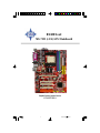
MSI G52-M7151X4 Bedienungsanleitung
- Kategorie
- Motherboards
- Typ
- Bedienungsanleitung
Dieses Handbuch eignet sich auch für

i
MS-7151 (v1.X) ATX Mainboard
G52-M7151X4
RX480 Neo2
English/French/German Version
未命名-1 2005/10/31, 下午 04:171

ii
FCC-B Radio Frequency Interference Statement
This equipment has been tested and found to comply with the limits for a class B
digital device, pursuant to part 15 of the FCC rules. These limits are designed to
provide reasonable protection against harmful interference when the equipment is
operated in a commercial environment. This equipment generates, uses and can
radiate radio frequency energy and, if not installed and used in accordance with the
instruction manual, may cause harmful interference to radio communications. Opera-
tion of this equipment in a residential area is likely to cause harmful interference, in
which case the user will be required to correct the interference at his own expense.
Notice 1
The changes or modifications not expressly approved by the party responsible for
compliance could void the user’s authority to operate the equipment.
Notice 2
Shielded interface cables and A.C. power cord, if any, must be used in order to
comply with the emission limits.
VOIR LA NOTICE D’INSTALLATION AVANT DE RACCORDER AU RESEAU.
Micro-Star International
MS-7151
This device complies with Part 15 of the FCC Rules. Operation is subject to the
following two conditions:
(1) this device may not cause harmful interference, and
(2) this device must accept any interference received, including interference that may
cause undesired operation.
未命名-1 2005/10/31, 下午 04:172

iii
Copyright Notice
The material in this document is the intellectual property of MICRO-STAR
INTERNATIONAL. We take every care in the preparation of this document, but no
guarantee is given as to the correctness of its contents. Our products are under
continual improvement and we reserve the right to make changes without notice.
Trademarks
All trademarks are the properties of their respective owners.
AMD, Athlon™, Athlon™ XP, Thoroughbred™, and Duron™ are registered trade-
marks of AMD Corporation.
Intel
®
and Pentium
®
are registered trademarks of Intel Corporation.
PS/2 and OS
®
/2 are registered trademarks of International Business Machines
Corporation.
Windows
®
95/98/2000/2003/NT/XP are registered trademarks of Microsoft Corporation.
Netware
®
is a registered trademark of Novell, Inc.
Award
®
is a registered trademark of Phoenix Technologies Ltd.
AMI
®
is a registered trademark of American Megatrends Inc.
Revision History
Revision Revision History Date
V1.0 First Release of 7151 v1.x PCB August 2005
with ATI RX480/SB400 chipsets
V1.1 First Release of 7151 v1.x PCB November 2005
with ATI RX480/SB400 chipsets (for EU)
Technical Support
If a problem arises with your system and no solution can be obtained from the user’s
manual, please contact your place of purchase or local distributor. Alternatively,
please try the following help resources for further guidance.
Visit the MSI website for FAQ, technical guide, BIOS updates, driver updates,
and other information: http://www.msi.com.tw/program/service/faq/
faq/esc_faq_list.php
Contact our technical staff at: support@msi.com.tw
未命名-1 2005/10/31, 下午 04:173

iv
1. Always read the safety instructions carefully.
2. Keep this User’s Manual for future reference.
3. Keep this equipment away from humidity.
4. Lay this equipment on a reliable flat surface before setting it up.
5. The openings on the enclosure are for air convection hence protects the equip-
ment from overheating. DO NOT COVER THE OPENINGS.
6. Make sure the voltage of the power source and adjust properly 110/220V be-
fore connecting the equipment to the power inlet.
7. Place the power cord such a way that people can not step on it. Do not place
anything over the power cord.
8. Always Unplug the Power Cord before inserting any add-on card or module.
9. All cautions and warnings on the equipment should be noted.
10. Never pour any liquid into the opening that could damage or cause electrical
shock.
11. If any of the following situations arises, get the equipment checked by a service
personnel:
† The power cord or plug is damaged.
† Liquid has penetrated into the equipment.
† The equipment has been exposed to moisture.
† The equipment has not work well or you can not get it work according to
User’s Manual.
† The equipment has dropped and damaged.
† The equipment has obvious sign of breakage.
12. DO NOT LEAVE THIS EQUIPMENT IN AN ENVIRONMENT UNCONDITIONED, STOR-
AGE TEMPERATURE ABOVE 60
0
C (140
0
F), IT MAY DAMAGE THE EQUIPMENT.
Safety Instructions
CAUTION: Danger of explosion if battery is incorrectly replaced.
Replace only with the same or equivalent type recommended by the
manufacturer.
未命名-1 2005/10/31, 下午 04:174

v
WEEE Statement
未命名-1 2005/10/31, 下午 04:175

vi
未命名-1 2005/10/31, 下午 04:176

vii
未命名-1 2005/10/31, 下午 04:177

viii
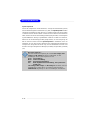
CONTENTS
FCC-B Radio Frequency Interference Statement...........................................................ii
Copyright Notice.............................................................................................................iii
Revision History.............................................................................................................iii
Technical Support.........................................................................................................iv
Safety Instructions........................................................................................................iv
English.......................................................................................................................E-1
User’s Manual.......................................................................................................E-3
Français....................................................................................................................F-1
Manuel d’utilisation...............................................................................................F-3
Deutsch....................................................................................................................G-1
Benutzerhandbuch.............................................................................................G-3
未命名-1 2005/10/31, 下午 04:178

E-1
User’s Manual
RX480 Neo2 Series
User’s Manual
English

E-2
MS-7151 ATX Mainboard

E-3
User’s Manual
Chapter 1. Getting
Started
RX480 Neo2 Series
User’s Manual
Thank you for choosing the RX480 Neo2 (MS-7151 v1.X) ATX
mainboard. The RX480 Neo2 mainboard is based on ATi
®
RX480 &
ATi
®
SB400 chipsets for optimal system efficiency. Designed to fit the
advanced AMD
®
K8 Athlon 64 FX processor, the RX480 Neo2 deliv-
ers a high performance and professional desktop platform solution.

E-4
MS-7151 ATX Mainboard
Mainboard Specifications
CPU
† Supports 64-bit AMD
®
Athlon 64 and Athlon 64 FX processor (Socket 939)
† Supports up to 4200+ Athlon 64 FX or higher CPU
(For the latest information about CPU, please visit http://www.msi.com.tw/pro-
gram/products/mainboard/mbd/pro_mbd_cpu_support.php)
Chipset
† ATI
®
RX480 Chipset
- HyperTransport
TM
connection to AMD K8 Athlon64 processor
- 8 or 16 bit control/address/data transfer both directions
- 1000/800/600/400/200 MHz “Double Data Rate” operation both direction
- Compliant with PCI Express 1.0a specifications (one x16 graphics interface,
which can be divided into two smaller links for use by other devices)
† ATI
®
SB400 Chipset
- Supports dual channel native SATA controller up to 150MB/s with RAID 0 or 1
- Integrated Hardware Sound Blaster/Direct Sound AC97 audio
- Ultra DMA 66/100/133 master mode PCI EIDE controller
- ACPI & PC2001 compliant enhanced power management
- Supports USB2.0 up to 8 ports
Main Memory
† Supports dual channel, four memory banks DDR 333/400, using two 184-pin
DDR DIMMs
† Supports a maximum memory size up to 2GB without ECC
† Supports 2.5v DDR SDRAM DIMM
(For the updated supporting memory modules, please visit http://www.msi.com.
tw/program/products/mainboard/mbd/pro_mbd_trp_list.php.)
Slots
† One PCI Express x16 slot (supports PCI Express Bus specification v1.0a compliant)
† One PCI Express x1 slot
† Four 32-bit Master 3.3V/5V PCI Bus slots
Onboard IDE
† An IDE controller on the ATI
®
SB400 chipset provides IDE HDD/CD-ROM with PIO,
Bus Master and Ultra DMA 133/100/66 operation modes, 4X ultra DMA 100/66/33
† Can connect up to 4 IDE devices
Onboard Serial ATA
† Supports 4 SATA ports with up to 150MB/s transfer rate

E-5
User’s Manual
USB Interface
† 8 USB ports
- 4 ports in the rear I/O, 4 ports via the external bracket
LAN (optional)
† Realtek
®
8100C/8110SB LAN chip (Optional)
- Integrated Fast Ethernet MAC and PHY in one chip
- Supports 10Mb/s and 100Mb/s and 1000Mb/s (1000Mb/s for 8110SB only)
- Compliance with PCI v2.2
- Supports ACPI Power Management
Audio
† 8 channels software audio codec RealTek ALC850
- Compliance with AC97 v2.3 Spec.
- Meets PC2001 audio performance requirement.
On-Board Peripherals
† On-Board Peripherals include:
- 1 floppy port supports 1 FDD with 360K, 720K, 1.2M, 1.44M and 2.88Mbytes
- 2 serial ports (COM1 on the rear, COM2 with pinheader)
- 1 parallel port supporting SPP/EPP/ECP mode
- 8 USB2.0 ports (Rear*4/Front*4)
- 1 Audio (Line-Outx3, Line-In, MIC In, SPDIF Out (Coaxial/Fibre) port
- 1 RJ-45 LAN Jack
- 2 IDE ports support 4 IDE devices
- 4 serial ATA ports
BIOS
† The mainboard BIOS provides “Plug & Play” BIOS which detects the peripheral
devices and expansion cards of the board automatically.
† The mainboard provides a Desktop Management Interface (DMI) function which
MSI Reminds You...
1.Please note that users cannot install OS, either WinME or Win98,
in their SATA hard drives. Under these two OSs, SATA can only be
used as an ordinary storage device.
2.To create a bootable RAID volume for a Windows 2000 environment,
Microsoft’s Windows 2000 Service Pack 4 (SP4) is required. As
the end user cannot boot without SP4, a combination installation
CD must be created before attempting to install the operating sys-
tem onto the bootable RAID volume.
To create the combination installation CD, please refer to the fol-
lowing website:
http://www.microsoft.com/windows2000/downloads/
servicepacks/sp4/HFdeploy.htm

E-6
MS-7151 ATX Mainboard
records your mainboard specifications.
† Supports boot from LAN, USB Device 1.1 & 2.0, and SATA HDD.
Dimension
† ATX Form Factor: 30.5cm X 21.5cm
Mounting
† 6 mounting holes

E-7
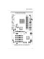
User’s Manual
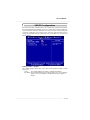
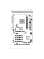
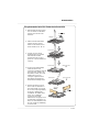
Mainboard Layout
RX480 Neo2 (MS-7151 v1.X) ATX Mainboard
1
4
5 5
6
3
2
4
2
7
6
4
8
9
10
1111
12
13
13
14
16
15
16
16
16
15

E-8
MS-7151 ATX Mainboard
1
2
4
3
6
5
7
9
11
8
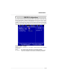
ATX 24-Pin Power Connector: JPWR1 This connector allows you to
connectto an ATX power suply.
ATX 12V Power Connector: JPWR2, JPWR3 This power connector is
provided to connect 12V power suply.
Floppy Disk Drive Connector: FDD1 This mainboard provides a stand-
ard floppy disk drive connector that supports 360K, 720K, 1.2M, 1.44M and
2.88M floppy disk types.
Fan Power Connecors: CPU_FAN, NB_FAN, SYS_FAN These fan
connectors support system cooling fan with +12V.
ATA 133 Hard Disk Connectors: IDE1 & IDE2 This mainboard has a 32-
bit Enhanced PCI IDE and Ultra DMA 66/100/133 controller that provides PIO
mode 0~4, Bus Master and Ultra DMA 66/100/133 function.
Serial ATA/ Serial ATA Connectors controlled by ATI SB400: SATA1 /
SATA2 / SATA3 / SATA4 The chipset of this mainboard is SB400 which
supports four serial ATA connectors SATA1~SATA4. SATA1~SATA4 are
high-speed Serial ATA interface ports. Each supports serial ATA data rate
of 150 MB/s.
Chassis Intrusion Switch Connector: JCI1 This connector is con-
nected to a 2-pin chassis switch. If the chassis is opened, the switch will
be short.
CD-In Connector: JCD1 The connector is for CD-ROM audio connector.
Front Panel Audio Connector: JAUD1 This front panel audio connector
allows you to connect to the front panel audio.
Serial Port Header: JCOM1 (Optional) The mainboard offers one 9-pin
header as serial port to attach a serial mouse or other serial devices.
Front Panel Connectors: JFP1, JFP2 The mainboard provides one front
panel connector for electrical connection to the front panel switches and
LEDs.
10
JFP2
7
8
Power LED
Speaker
1
2
JFP1
1
2
9
10
HDD
LED
Reset
Switch
Power
LED
Power
Switch

E-9
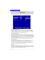
User’s Manual
14
12
13
15
16
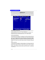
IrDA Infrared Module Header: JIR1 The connector allows you to
connect to IrDA Infrared module. You must configure the setting through
the BIOS setup to use the IR function. JIR1 is compliant with Intel Front
Panel I/O Connectivity Design Guide.
Front USB Connectors: JUSB1, JUSB2 This mainboard provides two
standard USB2.0 pin headers that allow you to connect USB devices via
an external USB bracket.
Clear CMOS Jumper: JCMOS1 There is a CMOS RAM onboard that has
a power supply from external battery to keep the data of system
configuration. With the CMOS RAM, the system can automatically boot OS
every time it is turned on. If you want to clear the system configuration, set
the JCMOS1 (Clear CMOS Jumper ) to clear data.
PCI Express slots: PCIE16X1 , PCI_ E1 The PCI Express slots support
high-bandwidth, low pin count, and serial interconnect technology. You
can insert the expansion cards to meet your needs. When adding or
removing expansion cards, make sure that you unplug the power supply
first. PCI Express architecture provides a high performance I/O infrastruc-
ture for Desktop Platforms with transfer rates starting at 2.5 Giga transfers
per second over a PCI Express x1 lane for Gigabit Ethernet, TV Tuners,
1394 controllers, and general purpose I/O. Also, desktop platforms with PCI
Express Architecture will be designed to deliver highest performance in
video, graphics, multimedia and other sophisticated applications. Moreover,
PCI Express architecture provides a high performance graphics infrastruc-
ture for Desktop Platforms doubling the capability of existing AGP 8x
designs with transfer rates of 4.0 GB/s over a PCI Express x16 lane for
graphics controllers, while PCI Express x1 supports transfer rate of 250
MB/s.
PCI Slots The PCI slots allow you to insert the expansion cards to meet
your needs. When adding or removing expansion cards, make sure that
you unplug the power supply first.

E-10
MS-7151 ATX Mainboard
Central Processing Unit: CPU
The mainboard supports AMD
®
Athlon64 processor. The mainboard uses a
CPU socket called Socket-939 for easy CPU installation. When you are installing
the CPU, make sure the CPU has a heat sink and a cooling fan attached on
the top to prevent overheating. If you do not have the heat sink and cooling
fan, contact your dealer to purchase and install them before turning on the
computer.
For the latest information about CPU, please visit http://www.msi.com.tw/pro-
gram/products/mainboard/mbd/pro_mbd_cpu_support.php.
MSI Reminds You...
Overheating
Overheating will seriously damage the CPU and system, always make
sure the cooling fan can work properly to protect the CPU from
overheating.
Replacing the CPU
While replacing the CPU, always turn off the ATX power supply or
unplug the power supply’s power cord from grounded outlet first to
ensure the safety of CPU.

E-11
User’s Manual
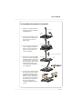
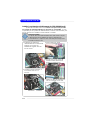
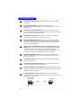
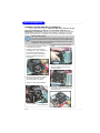
CPU Installation Procedures for Socket 939
1.Please turn off the power and
unplug the power cord before
installing the CPU.
2.Pull the lever sideways away
from the socket. Make sure to
raise the lever up to a 90-
degree angle.
3.Look for the gold arrow of the
CPU. The gold arrow should
point as shown in the picture.
The CPU can only fit in the
correct orientation.
4.If the CPU is correctly installed,
the pins should be completely
embedded into the socket and
can not be seen. Please note
that any violation of the correct
installation procedures may
cause permanent damages to
your mainboard.
5. Press the CPU down firmly into
the socket and close the lever.
As the CPU is likely to move
while the lever is being closed,
always close the lever with
your fingers pressing tightly on
top of the CPU to make sure
the CPU is properly and
completely embedded into the
socket.
Open Lever
90 degree
Sliding
Plate
Gold arrow
Gold arrow
Gold arrow
Correct CPU placement
O

E-12
MS-7151 ATX Mainboard
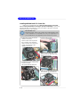
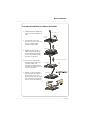
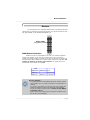
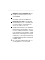
Installing AMD Athlon64 CPU Cooler Set
When you are installing the CPU, make sure the CPU has a heat sink
and a cooling fan attached on the top to prevent overheating. If you do not
have the heat sink and cooling fan, contact your dealer to purchase and install
them before turning on the computer.
MSI Reminds You...
Mainboard photos shown in this section are for demonstration of the
cooler installation for Socket 939 CPUs only. The appearance of
your mainboard may vary depending on the model you purchase.
2.Locate the Fix Lever, Safety Hook
and the Fixed Bolt.
Lift up the intensive fixed lever.
1.Position the cooling set onto the
retention mechanism.
Hook one end of the clip to hook
first, and then press down the
other end of the clip to fasten the
cooling set on the top of the
retention mechanism.
3.Fasten down the lever.
4.Make sure the safety hook com-
pletely clasps the fixed bolt of the
retention mechanism.
Safety Hook
Fixed Bolt
Fixed Lever
5.Attach the CPU Fan cable to the CPU
fan connector on the mainboard.
Seite wird geladen ...
Seite wird geladen ...
Seite wird geladen ...
Seite wird geladen ...
Seite wird geladen ...
Seite wird geladen ...
Seite wird geladen ...
Seite wird geladen ...
Seite wird geladen ...
Seite wird geladen ...
Seite wird geladen ...
Seite wird geladen ...
Seite wird geladen ...
Seite wird geladen ...
Seite wird geladen ...
Seite wird geladen ...
Seite wird geladen ...
Seite wird geladen ...
Seite wird geladen ...
Seite wird geladen ...
Seite wird geladen ...
Seite wird geladen ...
Seite wird geladen ...
Seite wird geladen ...
Seite wird geladen ...
Seite wird geladen ...
Seite wird geladen ...
Seite wird geladen ...
Seite wird geladen ...
Seite wird geladen ...
Seite wird geladen ...
Seite wird geladen ...
Seite wird geladen ...
Seite wird geladen ...
Seite wird geladen ...
Seite wird geladen ...
Seite wird geladen ...
Seite wird geladen ...
Seite wird geladen ...
Seite wird geladen ...
Seite wird geladen ...
Seite wird geladen ...
Seite wird geladen ...
Seite wird geladen ...
Seite wird geladen ...
Seite wird geladen ...
Seite wird geladen ...
Seite wird geladen ...
Seite wird geladen ...
Seite wird geladen ...
Seite wird geladen ...
Seite wird geladen ...
Seite wird geladen ...
Seite wird geladen ...
Seite wird geladen ...
Seite wird geladen ...
Seite wird geladen ...
Seite wird geladen ...
Seite wird geladen ...
Seite wird geladen ...
-
 1
1
-
 2
2
-
 3
3
-
 4
4
-
 5
5
-
 6
6
-
 7
7
-
 8
8
-
 9
9
-
 10
10
-
 11
11
-
 12
12
-
 13
13
-
 14
14
-
 15
15
-
 16
16
-
 17
17
-
 18
18
-
 19
19
-
 20
20
-
 21
21
-
 22
22
-
 23
23
-
 24
24
-
 25
25
-
 26
26
-
 27
27
-
 28
28
-
 29
29
-
 30
30
-
 31
31
-
 32
32
-
 33
33
-
 34
34
-
 35
35
-
 36
36
-
 37
37
-
 38
38
-
 39
39
-
 40
40
-
 41
41
-
 42
42
-
 43
43
-
 44
44
-
 45
45
-
 46
46
-
 47
47
-
 48
48
-
 49
49
-
 50
50
-
 51
51
-
 52
52
-
 53
53
-
 54
54
-
 55
55
-
 56
56
-
 57
57
-
 58
58
-
 59
59
-
 60
60
-
 61
61
-
 62
62
-
 63
63
-
 64
64
-
 65
65
-
 66
66
-
 67
67
-
 68
68
-
 69
69
-
 70
70
-
 71
71
-
 72
72
-
 73
73
-
 74
74
-
 75
75
-
 76
76
-
 77
77
-
 78
78
-
 79
79
-
 80
80


MSI G52-M7151X4 Bedienungsanleitung
- Kategorie
- Motherboards
- Typ
- Bedienungsanleitung
- Dieses Handbuch eignet sich auch für
in anderen Sprachen
- English: MSI G52-M7151X4 Owner's manual
- français: MSI G52-M7151X4 Le manuel du propriétaire
Verwandte Artikel
-
MSI K8M Neo-V Benutzerhandbuch
-
-
-
-
-
-
-
-
-
MSI G52-73881X4 Bedienungsanleitung
