LD Systems MAUI i1 Bedienungsanleitung
- Kategorie
- Soundbar-Lautsprecher
- Typ
- Bedienungsanleitung
Dieses Handbuch eignet sich auch für

USER´S MANUAL
BEDIENUNGSANLEITUNG
MANUEL D´UTILISATION
MANUAL DE USUARIO
INSTRUKCJA OBSŁUGI
MANUALE D´USO
MAUI
®
i1
INSTALLATION COLUMN SPEAKER
LDMAUIi1 (W)

CONTENTS / INHALTSVERZEICHNIS / CONTENU / CONTENIDO / TREŚĆ / CONTENUTO
ENGLISH
SAFETY INFORMATION 3
FEATURES 5
CONNECTIONS AND CONTROLS 5
MOUNTING 6
TECHNICAL DATA 8
MANUFACTURER´S DECLARATIONS 9
DEUTSCH
SICHERHEITSHINWEISE 10
EIGENSCHAFTEN 12
ANSCHLÜSSE UND BEDIENELEMENTE 12
MONTAGE 13
TECHNISCHE DATEN 15
HERSTELLERERKLÄRUNGEN 16
FRANCAIS
MESURES PRÉVENTIVES 17
CARACTÉRISTIQUES 19
CONNECTEURS ET ÉLÉMENTS DE COMMANDE 19
MONTAGE 20
CARACTÉRISTIQUES TECHNIQUES 22
DECLARATIONS 23
ESPAÑOL
MEDIDAS DE SEGURIDAD 24
CARACTER
ĺ
STICAS 26
CONEXIONES Y ELEMENTOS DE MANEJO 26
MONTAJE 27
DATOS TÉCNICOS 29
DECLARACIÓN DEL FABRICANTE 30
POLSKI
ŚRODKI OSTROŻNOŚCI 31
CHARAKTERYSTYKA 33
PRZYŁĄCZA I ELEMENTY OBSŁUGI 33
MONTAŻ 34
DANE TECHNICZNE 36
DEKLARACJE PRODUCENTA 37
ITALIANO
MISURE PRECAUZIONALI 38
CARATTERISTICHE 40
CONNESSIONI ED ELEMENTI DI COMANDO 40
MONTAGGIO 41
DATI TECNICI 43
DICHIARAZIONI DEL PRODUTTORE 44

3
DEUTSCHFRANCAIS
ESPAÑOL
ENGLISH
ITALIANO POLSKI
ENGLISH
YOU‘VE MADE THE RIGHT CHOICE!
We have designed this product to operate reliably over many years. LD Systems stands for this with its name and many years of experience
as a manufacturer of high-quality audio products. Please read this User‘s Manual carefully, so that you can begin making optimum use of
your LD Systems product quickly.
You can nd more information about LD-SYSTEMS at our Internet site WWW.LD-SYSTEMS.COM
SAFETY INFORMATION
1. Please read these instructions carefully.
2. Keep all information and instructions in a safe place.
3. Follow the instructions.
4. Observe all safety warnings. Never remove safety warnings or other information from the equipment.
5. Use the equipment only in the intended manner and for the intended purpose.
6. Use only sufciently stable and compatible stands and/or mounts (for xed installations). Make certain that wall mounts are properly
installed and secured. Make certain that the equipment is installed securely and cannot fall down.
7. During installation, observ e the applicable safety regulations for your country.
8. Never install and operate the equipment near radiators, heat registers, ovens or other sources of heat. Make certain that the equipment
is always installed so that is cooled sufciently and cannot overheat.
9. Never place sources of ignition, e.g., burning candles, on the equipment.
10. Ventilation slits must not be blocked.
11. Keep a minimum distance of 20 cm around and above the device.
12. Do not use this equipment in the immediate vicinity of water (does not apply to special outdoor equipment - in this case, observe the
special instructions noted below. Do not expose this equipment to ammable materials, uids or gases. Avoid direct sunlight!
13. Make certain that dripping or splashed water cannot enter the equipment. Do not place containers lled with liquids, such as vases or
drinking vessels, on the equipment.
14. Make certain that objects cannot fall into the device.
15. Use this equipment only with the accessories recommended and intended by the manufacturer.
16. Do not open or modify this equipment.
17. After connecting the equipment, check all cables in order to prevent damage or accidents, e.g., due to tripping hazards.
18. During transport, make certain that the equipment cannot fall down and possibly cause property damage and personal injuries.
19. If your equipment is no longer functioning properly, if uids or objects have gotten inside the equipment or if it has been damaged in
anot her way, switch it off immediately and unplug it from the mains outlet (if it is a powered device). This equipment may only be repaired
by authorized, qualied personnel.
20. Clean the equipment using a dry cloth.
21. Comply with all applicable disposal laws in your country. During disposal of packaging, please separate plastic and paper/cardboard.
22. Plastic bags must be kept out of reach of children.
23. Please note that changes or modications not expressly approved by the party responsible for compliance could void the user´s
authority to operate the equipment.
FOR EQUIPMENT THAT CONNECTS TO THE POWER MAINS
24. CAUTION: If the power cord of the device is equipped with an earthing contact, then it must be connected to an outlet with a protective
ground. Never deactivate the protective ground of a power cord.
25. If the equipment has been exposed to strong uctuations in temperature (for example, after transport), do not switch it on immediately.
Moisture and condensation could damage the equipment. Do not switch on the equipment until it has reached room temperature.
26. Before connecting the equipment to the power outlet, rst verify that the mains voltage and frequency match the values specied on
the equipment. If the equipment has a voltage selection switch, connect the equipment to the power outlet only if the equipment values
and the mains power values match. If the included power cord or power adapter does not t in your wall outlet, contact your electrician.
27. Do not step on the power cord. Make certain that the power cable does not become kinked, especially at the mains outlet and/or power
adapter and the equipment connector.
28. When connecting the equipment, make certain that the power cord or power adapter is always freely accessible. Always disconnect the
equipment from the power supply if the equipment is not in use or if you want to clean the equipment. Always unplug the power cord and
power adapter from the power outlet at the plug or adapter and not by pulling on the cord. Never touch the power cord and power adapter
with wet hands.
29. Whenever possible, avoid switching the equipment on and off in quick succession because otherwise this can shorten the useful life of
the equipment.
30. IMPORTANT INFORMATION: Replace fuses only with fuses of the same type and rating. If a fuse blows repeatedly, please contact an
authorised service centre.
31. To disconnect the equipment from the power mains completely, unplug the power cord or power adapter from the power outlet.
32. If your device is equipped with a Volex power connector, the mating Volex equipment connector must be unlocked before it can be
removed. However, this also means that the equipment can slide and fall down if the power cable is pulled, which can lead to personal
injuries and/or other damage. For this reason, always be careful when laying cables.
33. Unplug the power cord and power adapter from the power outlet if there is a risk of a lightning strike or before extended periods
of disuse.

4
ITALIANO
POLSKI
ESPAÑOL
FRANCAIS
DEUTSCH
ENGLISH
34. The appliance is not to be used by persons (including children) with reduced physical, sensory or mental capabilities, or lack of experience
and knowledge.
35. Children must be instructed not to play with the device.
36. If the power cord of the device is damaged, do not use the device. The power cord must be replaced by an adequate cable or assembly from an
authorized service center.
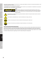
CAUTION:
To reduce the risk of electric shock, do not remove cover (or back). There are no user serviceable
parts inside. Maintenance and repairs should be exclusively carried out by qualied service
personnel.
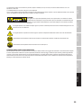
The warning triangle with lightning symbol indicates dangerous uninsulated voltage inside the unit, which may cause an
electrical shock.
The warning triangle with exclamation mark indicates important operating and maintenance instructions.
Warning! This device is designed for use below 2000 metres in altitude.
Warning! This product is not intended for use in tropical climates.
CAUTION! HIGH VOLUMES IN AUDIO PRODUCTS!
This device is meant for professional use. Therefore, commercial use of this equipment is subject to the respectively applicable national ac-
cident prevention rules and regulations. As a manufacturer, Adam Hall is obligated to notify you formally about the existence of potential
health risks.
Hearing damage due to high volume and prolonged exposure: When in use, this product is capable of producing high sound-pressure levels
(SPL) that can lead to irreversible hearing damage in performers, employees, and audience members. For this reason, avoid prolonged
exposure to volumes in excess of 90 dB.
NOTE: This equipment has been tested and found to comply with the limits for a Class B digital device, pursuant to Part 15 of the FCC
Rules. These limits are designed to provide reasonable protection against harmful interference in a residential installation. This equip-
ment generates, uses and can radiate radio frequency energy and, if not installed and used in accordance with the instructions, may cause
harmful interference to radio communications. However, there is no guarantee that interference will not occur in a particular installation.
If this equipment does cause harmful interference to radio or television reception, which can be determined by turning the equipment off
and on, the user is encouraged to try to correct the interference by one or more of the following measures:
– Reorient or relocate the receiving antenna.
– Increase the separation between the equipment and receiver.
– Connect the equipment into an outlet on a circuit different from that to which the receiver is connected.
– Consult the dealer or an experienced radio/TV technician for help.

5
DEUTSCHFRANCAIS
ESPAÑOL
ENGLISH
ITALIANO POLSKI
FEATURES
· Passive column speaker for wall and ceiling installation with 9 x 3“ mid-frequency drivers and 2 x 1“ neodymium HF drivers
· Sophisticated passive crossover network for balanced frequency response
· Auto-reset overload protection for tweeters
· 120 W RMS capacity at 8 ohms
· Input selector: 8 ohms (transformer bypass) / 100 V / 70 V
· Four 100 V / 70 V transformer taps: 60 W / 30 W / 15 W / 7.5 W
· Transformer with extremely low saturation
· Consistent sound dispersion thanks to BEM-optimised waveguide; wide horizontal and controlled vertical sound dispersion
· U-bracket included in scope of supply, adjustable tilting bracket optionally available
· Four-pole terminal block connector for simple parallel connection of loudspeakers
· IP65 protected, aluminium speaker grille and weatherproof membrane for outdoor installation
· Available in 2 colours: white (RAL9010) and black (RAL9005)
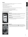
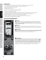
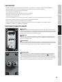
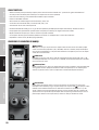
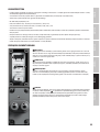
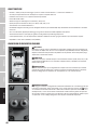
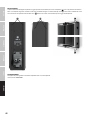
CONNECTIONS AND CONTROLS
3
1
2
1
INPUT SELECT
4-way selector to match installation loudspeaker to a 70 V or 100 V installation amplifier or an amplifier
with low impedance output (8 Ω/120 W RMS). Select the appropriate position before connecting. Both
middle positions are intended for use with 100 V installation amplifiers.
2
POWER SELECT
4-way switch for selection of the required transformer tap (60 W/30 W/15 W/7.5 W). If 8 Ω/120 W RMS is
selected on the INPUT SELECT switch, the internal transformer is bypassed.
3
SPEAKER IN/THRU
Terminal block for connection of an installation amplifier and for sending the amplifier signal to the
additional loudspeakers in parallel (terminal block supplied). When wiring, please ensure correct
polarity (see illustration above terminal block).
4
55
4
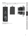
COVER PLATE
For outdoor installations, use the supplied cover plate to protect the connectors and switches from
wetness and humidity. The cable glands in the cover plate
5
are suitable for round cables with an ex-
ternal diameter of up to 7 mm. Ensure that the rubber gasket is correctly positioned before securing the
cover plate to the speaker housing. Then tighten the locking nuts on the cable glands. Use the supplied
blanking plugs to seal any open cable glands if only one cable is used to control the speaker.

6
ITALIANO
POLSKI
ESPAÑOL
FRANCAIS
DEUTSCH
ENGLISH
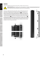
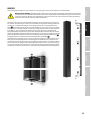
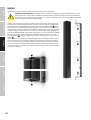
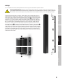
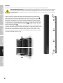
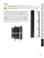
MOUNTING
Thanks to the supplied U-bracket, the speaker can be installed in a suitable location on a level surface.
Important safety notice: Overhead mounting requires extensive experience, including the calculation of the load limit values of the
installation material and regular safety inspection of all installation materials and speakers. If you do not have these qualifications,
do not attempt to perform an installation yourself. Refer instead to a qualified professional.
A
A
A
A
C
C
The U-bracket is supplied installed to the column speaker. Loosen and remove the M8 screws on the
top and bottom of the speaker and remove the bracket and the washers from the speaker. Screw
the U-bracket (in a suitable position) to a load-bearing wall or ceiling
A
. Use suitable screws and
plugs etc. and ensure secure installation. (9 mm hole diameter, screws, plugs etc. not supplied.) Lift
the speaker into the bracket so that the thread locations in the speaker and the holes in the bracket
are aligned. Use the previously removed M8 screws and washers as shown in the illustrations (place
washers between the bracket and the speaker), adjust the dispersion angle as desired and tighten the
screws with a suitable tool
B
. The U-bracket is also equipped with feed holes for signal cables
C
.
Tip: Install the U-bracket on a wall with the slanted recess in the slot facing upwards. Place a washer on
the mounting hole on the top end of the speaker and partially screw a suitable screw into the thread.
Lift the speaker into the U-bracket and insert the installation screw into the slanted recess in the slot,
then pull the speaker forwards as far as possible. Now a washer and installation screw can be easily
positioned and secured at the bottom of the speaker.
B
B

7
DEUTSCHFRANCAIS
ESPAÑOL
ENGLISH
ITALIANO POLSKI
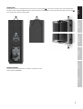
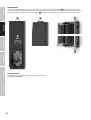
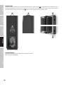
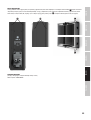
SECURING POINTS
Four M5 threads serve as securing points which can be used to secure the speaker
A
. To do so, loosen a housing screw at the required position
and replace it with a suitable M5 ring bolt. M5 threads for the attachment of an M5 ringbolt are located on the top and bottom of the U-bracket
B
.
Use a suitable safety cable to secure the speaker.
B
B
AA
OPTIONAL ACCESSORIES
An adjustable tilt-and-turn wall bracket is available as an optional accessory.
Product number: LDMAUII1WMBT

8
ITALIANO
POLSKI
ESPAÑOL
FRANCAIS
DEUTSCH
ENGLISH
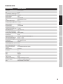
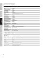
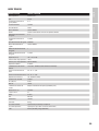
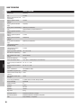
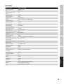
TECHNICAL DATA
Item number LDMAUIi1 / LDMAUIi1W
Product type PA loudspeaker
Type Passive
Low/mid driver dimensions 9 x 3"
Woofer size 76.2 mm
Woofer magnet Ferrit
Woofer brand Custom-made
Horn BEM optimized CD Horn
HF driver dimensions 2 x 1"
HF driver Size 25.4 mm
HF driver magnet Neodymium
HF driver brand Custom-made
HF driver voice coil 1
HF driver Voice Coil 25.4 mm
Dispersion (H x V) 120 ° x 30 ° (-6 dB)
Low impedance RMS power 120 W
Low impedance Peak power 480 W (>200 Hz)
Nominal impedance 8 Ohms
Input selector switch 70 V - 100 V - 8 0hms (transformer bypass)
100V Transformer power taps 60 - 30 - 15 - 7.5 W
70V Transformer power taps 60 - 30 - 15 - 7.5 W
Frequency response 130 - 19000 Hz (-10dB)
Crossover frequency 2500 Hz
SPL (1W/1m) 94 dB
Max. SPL 116 dB
Speaker input connections 4-pole Terminal Block. Pitch 5.08 mm
Cabinet material Aluminum
IP rating 65
Width 85 mm
Height 985 mm
Depth 105 mm
Net weight 8.6 kg
Included accessories U-Bracket for surface mount
Optional accessories Bracket for tilt installation applications
Color White (RAL9010) / Black (9005)

9
DEUTSCHFRANCAIS
ESPAÑOL
ENGLISH
ITALIANO POLSKI
MANUFACTURER´S DECLARATIONS
MANUFACTURER‘S WARRANTY & LIMITATIONS OF LIABILITY
You can nd our current warranty conditions and limitations of liability at: https://cdn-shop.adamhall.com/media/pdf/MANUFACTURERS-DECLARATIONS_
LD_SYSTEMS.pdf To request warranty service for a product, please contact Adam Hall GmbH, Adam-Hall-Str. 1,
61267 Neu Anspach / Email: [email protected] / +49 (0)6081 / 9419-0.
CORRECT DISPOSAL OF THIS PRODUCT
(valid in the European Union and other European countries with a differentiated waste collection system)
This symbol on the product, or on its documents indicates that the device may not be treated as household waste. This is to avoid environ-
mental damage or personal injury due to uncontrolled waste disposal. Please dispose of this product separately from other waste and have it
recycled to promote sustainable economic activity. Household users should contact either the retailer where they purchased this product, or their
local government ofce, for details on where and how they can recycle this item in an environmentally friendly manner. Business users should
contact their supplier and check the terms and conditions of the purchase contract. This product should not be mixed with other commercial waste
for disposal.
FCC STATEMENT
This device complies with Part 15 of the FCC Rules. Operation is subject to the following two conditions:
(1) This device may not cause harmful interference, and
(2) This device must accept any interference received, including interference that may cause undesired operation
EU DECLARATION OF CONFORMITY
Hereby, Adam Hall GmbH declares that this radio equipment type is in compliance with Directive 2014/53/EU.
The full text of the EU declaration of conformity is available at the following
internet address: www.adamhall.com/compliance/
CE Compliance
Adam Hall GmbH states that this product meets the following guidelines (where applicable):
R&TTE (1999/5/EC) or RED (2014/53/EU) from June 2017
Low voltage directive (2014/35/EU)
EMV directive (2014/30/EU)
RoHS (2011/65/EU)
The complete declaration of conformity can be found at www.adamhall.com.
Furthermore, you may also direct your enquiry to [email protected].

10
ITALIANO
POLSKI
ESPAÑOL
FRANCAIS
DEUTSCH
ENGLISH
DEUTSCH
SIE HABEN DIE RICHTIGE WAHL GETROFFEN!
Dieses Gerät wurde unter hohen Qualitätsanforderungen entwickelt und gefertigt, um viele Jahre einen reibungslosen Betrieb zu gewährleisten.
Dafür steht LD Systems mit seinem Namen und der langjährigen Erfahrung als Hersteller hochwertiger Audioprodukte. Bitte lesen Sie diese Bedie-
nungsanleitung sorgfältig, damit Sie Ihr neues Produkt von LD Systems schnell optimal einsetzen können.
Mehr Informationen zu LD SYSTEMS nden Sie auf unserer Internetseite WWW.LD-SYSTEMS.COM
SICHERHEITSHINWEISE
1. Lesen Sie diese Anleitung bitte sorgfältig durch.
2. Bewahren Sie alle Informationen und Anleitungen an einem sicheren Ort auf.
3. Befolgen Sie die Anweisungen.
4. Beachten Sie alle Warnhinweise. Entfernen Sie keine Sicherheitshinweise oder andere Informationen vom Gerät.
5. Verwenden Sie das Gerät nur in der vorgesehenen Art und Weise.
6. Verwenden Sie ausschließlich stabile und passende Stative bzw. Befestigungen (bei Festinstallationen). Stellen Sie sicher, dass Wandhalterungen
ordnungsgemäß installiert und gesichert sind. Stellen Sie sicher, dass das Gerät sicher installiert ist und nicht herunterfallen kann.
7. Beachten Sie bei der Installation die für Ihr Land geltenden Sicherheitsvorschriften.
8. Installieren und betreiben Sie das Gerät nicht in der Nähe von Heizkörpern, Wärmespeichern, Öfen oder sonstigen Wärmequellen. Sorgen Sie dafür,
dass das Gerät immer so installiert ist, dass es ausreichend gekühlt wird und nicht überhitzen kann.
9. Platzieren Sie keine Zündquellen wie z.B. brennende Kerzen auf dem Gerät.
10. Lüftungsschlitze dürfen nicht blockiert werden.
11. Halten Sie einen Mindestabstand von 20 cm seitlich und oberhalb des Geräts ein.
12. Betreiben Sie das Gerät nicht in unmittelbarer Nähe von Wasser. Bringen Sie das Gerät nicht mit brennbaren Materialien, Flüssigkeiten oder
Gasen in Berührung. Direkte Sonneneinstrahlung vermeiden!
13. Sorgen Sie dafür, dass kein Tropf- oder Spritzwasser in das Gerät eindringen kann. Stellen Sie keine mit Flüssigkeit gefüllten Behältnisse wie
Vasen oder Trinkgefäße auf das Gerät.
14. Sorgen Sie dafür, dass keine Gegenstände in das Gerät fallen können.
15. Betreiben Sie das Gerät nur mit dem vom Hersteller empfohlenen und vorgesehenen Zubehör.
16. Öffnen Sie das Gerät nicht und verändern Sie es nicht.
17. Überprüfen Sie nach dem Anschluss des Geräts alle Kabelwege, um Schäden oder Unfälle, z. B. durch Stolperfallen zu vermeiden.
18. Achten Sie beim Transport darauf, dass das Gerät nicht herunterfallen und dabei möglicherweise Sach- und Personenschäden
verursachen kann.
19. Wenn Ihr Gerät nicht mehr ordnungsgemäß funktioniert, Flüssigkeiten oder Gegenstände in das Geräteinnere gelangt sind, oder das Gerät an-
derweitig beschädigt wurde, schalten Sie es sofort aus und trennen es von der Netzsteckdose (sofern es sich um ein aktives Gerät handelt). Dieses
Gerät darf nur von autorisiertem Fachpersonal repariert werden.
20. Verwenden Sie zur Reinigung des Geräts ein trockenes Tuch.
21. Beachten Sie alle in Ihrem Land geltenden Entsorgungsgesetze. Trennen Sie bei der Entsorgung der Verpackung bitte Kunststoff und Papier bzw.
Kartonagen voneinander.
22. Kunststoffbeutel müssen außer Reichweite von Kindern aufbewahrt werden.
23. Sämtliche vom Benutzer vorgenommenen Änderungen und Modikationen, denen die für die Einhaltung der Richtlinien verantwortliche Partei
nicht ausdrücklich zugestimmt hat, können zum Entzug der Betriebserlaubnis für das Gerät führen.
BEI GERÄTEN MIT NETZANSCHLUSS
24. ACHTUNG: Wenn das Netzkabel des Geräts mit einem Schutzkontakt ausgestattet ist, muss es an einer Steckdose mit Schutzleiter angeschlossen
werden. Deaktivieren Sie niemals den Schutzleiter eines Netzkabels.
25. Schalten Sie das Gerät nicht sofort ein, wenn es starken Temperaturschwankungen ausgesetzt war (beispielsweise nach dem Transport). Feuch-
tigkeit und Kondensat könnten das Gerät beschädigen. Schalten Sie das Gerät erst ein, wenn es Zimmertemperatur erreicht hat.
26. Bevor Sie das Gerät an die Steckdose anschließen, prüfen Sie zuerst, ob die Spannung und die Frequenz des Stromnetzes mit den auf dem Gerät
angegebenen Werten übereinstimmen. Verfügt das Gerät über einen Spannungswahlschalter, schließen Sie das Gerät nur an die Steckdose an,
wenn die Gerätewerte mit den Werten des Stromnetzes übereinstimmen. Wenn das mitgelieferte Netzkabel bzw. der mitgelieferte Netzadapter
nicht in Ihre Netzsteckdose passt, wenden Sie sich an Ihren Elektriker.
27. Treten Sie nicht auf das Netzkabel. Sorgen Sie dafür, dass spannungsführende Kabel speziell an der Netzbuchse bzw. am Netzadapter und der
Gerätebuchse nicht geknickt werden.
28. Achten Sie bei der Verkabelung des Geräts immer darauf, dass das Netzkabel bzw. der Netzadapter stets frei zugänglich ist. Trennen Sie das
Gerät stets von der Stromzuführung, wenn das Gerät nicht benutzt wird, oder Sie das Gerät reinigen möchten. Ziehen Sie Netzkabel und Netzadapter
immer am Stecker bzw. am Adapter und nicht am Kabel aus der Steckdose. Berühren Sie Netzkabel und Netzadapter niemals mit nassen Händen.
29. Schalten Sie das Gerät möglichst nicht schnell hintereinander ein und aus, da sonst die Lebensdauer des Geräts beeinträchtigt werden könnte.
30. WICHTIGER HINWEIS: Ersetzen Sie Sicherungen ausschließlich durch Sicherungen des gleichen Typs und Wertes. Sollte eine Sicherung wiederholt
auslösen, wenden Sie sich bitte an ein autorisiertes Servicezentrum.
31. Um das Gerät vollständig vom Stromnetz zu trennen, entfernen Sie das Netzkabel bzw. den Netzadapter aus der Steckdose.
32. Wenn Ihr Gerät mit einem verriegelbaren Netzanschluss bestückt ist, muss der passende Gerätestecker entsperrt werden, bevor er entfernt wer-
den kann. Das bedeutet aber auch, dass das Gerät durch ein Ziehen am Netzkabel verrutschen und herunterfallen kann, wodurch Personen verletzt
werden und/oder andere Schäden auftreten können. Verlegen Sie Ihre Kabel daher immer sorgfältig.
33. Entfernen Sie Netzkabel und Netzadapter aus der Steckdose bei Gefahr eines Blitzschlags oder wenn Sie das Gerät länger nicht verwenden.
34. Das Gerät darf nicht von Personen (einschließlich Kindern) mit eingeschränkten körperlichen, sensorischen oder geistigen Fähigkeiten oder
mangelnder Erfahrung und Kenntnis benutzt werden.

11
DEUTSCHFRANCAIS
ESPAÑOL
ENGLISH
ITALIANO POLSKI
35. Kinder müssen angewiesen werden, nicht mit dem Gerät zu spielen.
36. Wenn das Netzkabel des Geräts beschädigt ist, darf das Gerät nicht verwendet werden. Das Netzkabel muss durch ein adäquates Kabel oder eine
spezielle Baugruppe von einem autorisierten Service-Center ersetzt werden.
ACHTUNG
Entfernen Sie niemals die Abdeckung, da sonst das Risiko eines elektrischen Schlages besteht. Im In-
neren des Geräts benden sich keine Teile, die vom Bediener repariert oder gewartet werden können.
Lassen Sie Wartung und Reparaturen ausschließlich von qualiziertem Servicepersonal durchführen.
Das gleichseitige Dreieck mit Blitzsymbol warnt vor nichtisolierten, gefährlichen Spannungen im Geräteinneren, die einen elektrischen
Schlag verursachen können.
Das gleichseitige Dreieck mit Ausrufungszeichen kennzeichnet wichtige Bedienungs- und Wartungshinweise.
Warnung! Dieses Gerät ist für eine Nutzung bis zu einer Höhe von maximal 2000 Metern über dem Meeresspiegel bestimmt.
Warnung! Dieses Gerät ist nicht für den Einsatz in tropischen Klimazonen bestimmt.
ACHTUNG HOHE LAUTSTÄRKEN BEI AUDIOPRODUKTEN!
Dieses Gerät ist für den professionellen Einsatz vorgesehen. Der kommerzielle Betrieb dieses Geräts unterliegt den jeweils gültigen nationalen
Vorschriften und Richtlinien zur Unfallverhütung. Als Hersteller ist Adam Hall gesetzlich verpichtet, Sie ausdrücklich auf mögliche Gesundheitsrisiken
hinzuweisen. Gehörschäden durch hohe Lautstärken und Dauerbelastung: Bei der Verwendung dieses Produkts können hohe Schalldruckpegel
(SPL) erzeugt werden, die bei Künstlern, Mitarbeitern und Zuschauern zu irreparablen Gehörschäden führen können. Vermeiden Sie länger anhaltende
Belastung durch hohe Lautstärken über 90 dB.

12
ITALIANO
POLSKI
ESPAÑOL
FRANCAIS
DEUTSCH
ENGLISH
EIGENSCHAFTEN
· Passiver Säulenlautsprecher für Wand- und Deckenmontage mit 9 x 3“ Mittentöner und 2 x 1“ Neodym-HF-Treiber
· Technisch ausgefeilte passive Frequenzweiche für einen ausgeglichenen Frequenzgang
· Selbstrückstellender Überlastschutz für Hochtöner
· 120W RMS Belastbarkeit bei 8 Ohm
· Input-Wahlschalter: 8 Ohm (Transformator Bypass) / 100 V / 70 V
· Vier 100 V / 70 V Transformatorabgriffe: 60 W / 30 W / 15 W / 7,5 W
· Transformator mit extrem niedriger Sättigung
· Gleichmäßige Schallverteilung dank BEM-optimiertem Waveguide; breite horizontale und kontrollierte vertikale Schallverteilung
· U-Bügel im Lieferumfang enthalten, Halterung für die Montage mit variablem Neigungswinkel optional erhältlich
· Vierpoliger Klemmblockanschluss zum einfachen Parallelschalten von Lautsprechern
· IP65 Schutzart, Aluminium-Lautsprechergitter und wetterfeste Membranen für die Installation im Freien
· In 2 Farben erhältlich: Weiß (RAL9010) und Schwarz (RAL9005)
ANSCHLÜSSE UND BEDIENELEMENTE
3
1
2
1
INPUT SELECT
4-Weg-Schalter zum Anpassen des Installationslautsprechers an 70V bzw. 100V Installationsverstärker
und Verstärker mit niederohmigem Ausgang (8Ω/120W RMS). Bringen Sie den Schalter vor dem An-
schließen in die entsprechende Position. Beide mittleren Positionen sind für die Verwendung mit 100V
Installationsverstärkern vorgesehen.
2
POWER SELECT
4-Weg-Schalter zum Auswählen des gewünschten Transformatorabgriffs (60W / 30W / 15W / 7,5W). Ist am
Schalter INPUT SELECT die Einstellung 8Ω / 120W RMS gewählt, befindet sich der interne Transformator
nicht im Signalweg.
3
SPEAKER IN/THRU
Klemmblock-Terminal zum Anschließen eines Installationsverstärkers und zum Weiterleiten des Verstär-
kersignals parallel an einen zusätzlichen Lautsprecher (Klemmblock im Lieferumfang). Achten Sie beim
Verkabeln auf die korrekte Polung (siehe Aufdruck über Klemmblock-Terminal).
4
55
4
VERSCHLUSSDECKEL
Um bei der Outdoor-Montage Anschlussterminal und Schalter vor Nässe und Feuchtigkeit zu schützen,
nutzen Sie den beigefügten Verschlussdeckel. Die Kabeldurchführungen des Verschlussdeckels
5
sind für Rundkabel mit einem Außendurchmesser von bis zu 7mm geeignet. Vergewissern Sie sich vor
dem Verschrauben des Verschlussdeckels mit dem Lautsprechergehäuse davon, dass der Gummi-
dichtring des Deckels korrekt eingesetzt ist. Ziehen Sie die Klemmmuttern der Kabeldurchführungen
anschließend fest. Verwenden Sie den beiliegenden Blindstopfen und verschließen damit die offene
Kabeldurchführung, falls Sie nur ein Kabel zur Ansteuerung des Lautsprechers verwenden.

13
DEUTSCHFRANCAIS
ESPAÑOL
ENGLISH
ITALIANO POLSKI
MONTAGE
Dank des beigefügten U-Bügels kann der Lautsprecher an einer geeigneten Stelle auf einer ebenen Fläche montiert werden.
Wichtiger Sicherheitshinweis: Überkopfmontage erfordert umfassende Erfahrung, einschließlich der Berechnung der Grenzwerte
für die Arbeitslast, des verwendeten Installationsmaterials und der regelmäßigen Sicherheitsüberprüfung aller Installationsmate-
rialien und Lautsprecher. Wenn Sie diese Qualifikationen nicht haben, versuchen Sie nicht, eine Installation selbst durchzuführen,
sondern nutzen Sie die Hilfe von professionellen Unternehmen.
A
A
A
A
C
C
Der U-Bügel ist bei Lieferung am Säulenlautsprecher montiert. Lösen und entfernen Sie die M8 Schrau-
ben auf Ober- und Unterseite des Lautsprechers und nehmen den Bügel und die Unterlegscheiben vom
Lautsprecher. Schrauben Sie den U-Bügel an einer geeigneten Stelle an eine tragfähige Wand oder
Decke
A
. Verwenden Sie dazu geeignete Schrauben und Dübel etc. und achten auf festen Halt (9mm
Lochdurchmesser, Schrauben, Dübel etc. nicht im Lieferumfang enthalten). Heben Sie den Lautsprecher
in den Bügel, so, dass die Positionen der Gewinde im Lautsprecher und die der Schraublöcher im
Bügel übereinstimmen. Verwenden Sie jetzt die zuvor entfernten M8 Schrauben und Unterlegscheiben
gemäß der Abbildungen (Unterlegscheiben zwischen Bügel und Lautsprecher positionieren), stellen die
gewünschte Abstrahlrichtung ein und ziehen die Schrauben mit einem geeigneten Werkzeug fest
B
.
Im U-Bügel befinden sich außerdem Löcher zum Durchführen von Signalkabeln
C
.
Tipp: Montieren Sie den U-Bügel mit der schrägen Aussparung im Langloch nach oben zeigend an eine
Wand. Legen Sie eine Unterlegscheibe auf das Montageloch am oberen Ende des Lautsprechers und
schrauben eine entsprechende Schraube durch die Unterlegscheibe nur halb in das Gewinde. Heben Sie
den Lautsprecher in den U-Bügel, führen dabei die Montageschraube durch die schräge Aussparung in
das Langloch und ziehen den Lautsprecher nach vorne bis zum Anschlag. Nun können Unterlegscheibe
und Montageschraube am unteren Ende des Lautsprechers bequem positioniert und befestigt werden.
B
B

14
ITALIANO
POLSKI
ESPAÑOL
FRANCAIS
DEUTSCH
ENGLISH
SICHERUNGSPUNKTE
Als Sicherungspunkte dienen vier M5 Gewinde, die zum Sichern des Lautsprechers genutzt werden können
A
. Lösen Sie hierfür eine Gehäuse-
schraube an der geeigneten Stelle und ersetzen sie durch eine geeignete M5 Ringschraube. M5 Gewinde zum Anbringen einer M5 Ringschraube an
den U-Bügel befinden sich an Ober- und Unterseite des Bügels
B
. Verwenden Sie ein geeignetes Sicherungsseil zum Sichern des Lautsprechers.
B
B
AA
OPTIONALES ZUBEHÖR
Ein schwenk- und neigbarer Wandhalter ist als optionales Zubehör erhältlich.
Artikelnummer: LDMAUII1WMBT

15
DEUTSCHFRANCAIS
ESPAÑOL
ENGLISH
ITALIANO POLSKI
TECHNISCHE DATEN
Artikelbezeichnung LDMAUIi1 / LDMAUIi1W
Produkttyp PA-Lautsprecher
Typ Passiv
Tief-/Mitteltöner, Abmessungen 9 x 3"
Tieftöner, Abmessungen (mm) 76,2 mm
Magnet Tieftöner Ferrit
Marke Tieftöner Custom-Modell
Horn BEM-optimiertes CD-Horn
Hochtöner, Abmessungen 2 x 1"
Hochtöner, Abmessungen (mm) 25,4 mm
Magnet Hochtöner Neodym
Marke Hochtöner Custom-Modell
Schwingspule Hochtöner 1
Schwingspule Hochtöner (mm) 25,4 mm
Abstrahlwinkel (H x V) 120° x 30° (-6 dB)
Leistung (RMS), niederohmig 120 W
Leistung (Peak), niederohmig 480 W (>200 Hz)
Nennimpedanz 8 Ohm
Eingangswahlschalter 70 V - 100 V - 8 Ohm (Transformator-Bypass)
100-V-Transformator-Abgriffe 60 - 30 - 15 - 7,5 W
70-V-Transformator-Abgriffe 60 - 30 - 15 - 7,5 W
Frequenzgang 130 – 19.000 Hz (-10 dB)
Übernahmefrequenz 2500 Hz
Schalldruckpegel (SPL, 1 W / 1 m) 94 dB
Max. Schalldruckpegel (SPL) 116 dB
Anschlusstyp Lautsprecher-
eingänge
4-Pol-Klemmleiste Abstand 5,08 mm
Gehäusematerial Aluminium
IP-Schutzart 65
Breite 85 mm
Höhe 985 mm
Tiefe 105 mm
Gewicht (netto) 8,6 kg
Zubehör im Lieferumfang U-Bügel zur Montage an Flächen
Optionales Zubehör Schwenk- und neigbarer Wandhalter
Farbe Weiß (RAL9010) / Schwarz (9005)

16
ITALIANO
POLSKI
ESPAÑOL
FRANCAIS
DEUTSCH
ENGLISH
HERSTELLERERKLÄRUNGEN
HERSTELLERGARANTIE & HAFTUNGSBESCHRÄNKUNG
Unsere aktuellen Garantiebedingungen und Haftungsbeschränkung nden Sie unter: https://cdn-shop.adamhall.com/media/pdf/MANUFACTURERS-
DECLARATIONS_LD_SYSTEMS.pdf. Im Service Fall wenden Sie sich bitte an Adam Hall GmbH, Adam-Hall-Str. 1,
61267 Neu Anspach / E-Mail [email protected] / +49 (0)6081 / 9419-0.
KORREKTE ENTSORGUNG DIESES PRODUKTS
(Gültig in der Europäischen Union und anderen europäischen Ländern mit Mülltrennung) Dieses Symbol auf dem Produkt oder dazugehörigen
Dokumenten weist darauf hin, dass das Gerät am Ende der Produktlebenszeit nicht zusammen mit dem normalen Hausmüll entsorgt werden
darf, um Umwelt- oder Personenschäden durch unkontrollierte Abfallentsorgung zu vermeiden. Bitte entsorgen Sie dieses Produkt getrennt von
anderen Abfällen und führen es zur Förderung nachhaltiger Wirtschaftskreisläufe dem Recycling zu. Als Privatkunde erhalten Sie Informationen zu
umweltfreundlichen Entsorgungsmöglichkeiten über den Händler, bei dem das Produkt erworben wurde, oder über die entsprechenden regionalen
Behörden. Als gewerblicher Nutzer kontaktieren Sie bitte Ihren Lieferanten und prüfen die ggf. vertraglich vereinbarten Konditionen zur Entsorgung der
Geräte. Dieses Produkt darf nicht zusammen mit anderen gewerblichen Abfällen entsorgt werden.
CE-Konformität
Hiermit erklärt die Adam Hall GmbH, dass dieses Produkt folgenden Richtlinien entspricht (soweit zutreffend):
R&TTE (1999/5/EG) bzw. RED (2014/53/EU) ab Juni 2017
Niederspannungsrichtlinie (2014/35/EU)
EMV-Richtlinie (2014/30/EU)
RoHS (2011/65/EU)
Die vollständige Konformitätserklärung nden Sie unter www.adamhall.com.
Des Weiteren können Sie diese auch unter [email protected] anfragen.
EG-KONFORMITÄTSERKLÄRUNG
Hiermit erklärt die Adam Hall GmbH, dass dieser Funkanlagentyp der Richtlinie 2014/53/EU entspricht.
Der vollständige Text der EU-Konformitätserklärung ist unter der folgenden
Internetadresse verfügbar: www.adamhall.com/compliance/

17
DEUTSCHFRANCAIS
ESPAÑOL
ENGLISH
ITALIANO POLSKI
FRANCAIS
VOUS AVEZ FAIT LE BON CHOIX!
Cet appareil a été développé et fabriqué en appliquant des exigences de qualité très élevées : il garantit des années de fonctionnement sans
problème. Grâce à de nombreuses années d‘expérience, LD Systems est un nom connu dans le domaine des produits audio haut de gamme. Veuillez
lire attentivement ce Manuel Utilisateur : vous apprendrez rapidement à utiliser votre appareil LD Systems de façon optimale.
Pour plus d‘informations sur LD Systems, visitez notre site Web, WWW.LD-SYSTEMS.COM
MESURES PRÉVENTIVES
1. Veuillez lire attentivement ce manuel.
2. Rangez tous les documents d‘information et d‘instructions en lieu sûr.
3. Veuillez suivre toutes les instructions
4. Observez tous les messages d‘avertissement N‘enlevez pas de l‘appareil les étiquettes de sécurité ou autres informations.
5. N‘utilisez l‘appareil que pour des applications et de la façon appropriées.
6. Utilisez exclusivement des pieds et des dispositifs de xation stables et adaptés lorsque l‘appareil est utilisé en installation xe. Assurez-vous que
les xations murales ont été montées correctement, et qu‘elles sont sécurisées. Vériez que l‘appareil est installé en toute sécurité, et qu‘il ne peut
pas tomber.
7. Lors de l‘installation, observez les règlementations de sécurité en vigueur dans votre pays.
8. N‘installez et n‘utilisez pas l‘appareil à proximité de radiateurs, d‘accumulateurs de chaleur, de fours ou de toute autre source de chaleur. Vériez
que l‘appareil est installé de façon à bénécier en permanence d‘un refroidissement efcace et qu‘il ne peut pas chauffer de façon excessive.
9. Ne placez aucune source de amme sur l‘appareil – par exemple, une bougie allumée.
10. Ne bloquez pas les ouïes d‘aération. Éviter toute exposition directe aux rayons du soleil !
11. Gardez une distance minimale de 20 cm autour et au-dessus de l‘appareil.
12. N‘utilisez pas l‘appareil à proximité immédiate d‘eau (à moins qu‘il ne s‘agisse d‘un appareil conçu pour une utilisation en extérieur – dans ce cas,
respectez les instructions correspondantes ci après) Ne mettez pas l‘appareil en contact avec des matériaux, des liquides ou des gaz inammables.
13. Vériez qu‘aucune projection ou liquide ne puisse s‘introduire dans l‘appareil. Ne posez sur l‘appareil aucun objet renfermant du liquide : vase,
verre d‘eau...
14. Vériez qu‘aucun petit objet ne puisse tomber à l‘intérieur de l‘appareil.
15. N‘utilisez avec cet appareil que des accessoires recommandés et approuvés par le fabricant.
16. N‘ouvrez pas l‘appareil, et n‘essayez pas de le modier.
17. Lors du branchement de l‘appareil, sécurisez le passage du câble secteur, an d‘éviter tout dommage ou accident, par exemple quelqu‘un qui
trébuche sur le câble.
18. Lors du transport, vériez que l‘appareil ne peut tomber, ce qui pourrait provoquer des dommages matériels et/ou corporels.
19. Si votre appareil ne fonctionne plus correctement, que de l‘eau ou des objets ont pénétré à l‘intérieur, ou qu‘il a été endommagé de quelque
façon que ce soit, éteignez-le immédiatement et débranchez sa prise secteur (s‘il s‘agit d‘un appareil alimenté). Cet appareil ne doit être réparé que
par un personnel autorisé.
20. Pour le nettoyage de l‘appareil, utilisez un chiffon sec.
21. Observez toutes les réglementations en vigueur dans votre pays pour mettre l‘appareil au rebut. Lorsque vous jetez l‘emballage de l‘appareil,
veuillez séparer plastique, papier et carton.
22. Les lms plastique doivent être mis hors de portée des enfants.
23. Veuillez noter que les changements ou modications n‘ayant pas été expressément approuvés par la partie responsable de la conformité
pourraient annuler le droit accordé à l‘utilisateur de faire fonctionner l‘équipement.
APPAREILS RELIÉS AU SECTEUR
24. ATTENTION : Si le câble de l‘appareil est muni d‘un l de terre, il doit être relié à une prise murale avec terre. Ne désactivez jamais la mise à la
terre d‘un appareil.
25. N‘allumez pas l‘appareil immédiatement s‘il a subi une grande différence de température ambiante (par exemple, lors du transport). L‘humidité
et la condensation pourraient l‘endommager. Ne mettez l‘appareil sous tension que lorsqu‘il est parvenu à la température de la pièce.
26. Avant de relier l‘appareil à la prise murale, vériez que la valeur et la fréquence de tension secteur sur laquelle il est réglé correspondent bien
à la valeur et à la fréquence de la tension secteur locale. Si l‘appareil possède un sélecteur de tension, ne le branchez sur la prise murale qu‘après
avoir vérié que la valeur réglée correspond à la valeur effective de la tension secteur. Si la che du cordon secteur ou du bloc adaptateur livré avec
votre appareil ne correspond pas au format de votre prise murale, veuillez consulter un électricien.
27. Ne piétinez pas le câble secteur. Assurez-vous que le câble secteur n‘est pas trop pincé, notamment au niveau de l‘arrière de l‘appareil (ou de son
adaptateur secteur) et de la prise murale.
28. Lors du branchement de l‘appareil, vériez que l‘accès au câble secteur ou au bloc adaptateur reste facile. Sortez la che secteur de la prise
murale dès que vous n‘utilisez pas l‘appareil pendant un certain temps, ou si vous désirez nettoyer l‘appareil. Pour ce faire, tirez toujours sur la che
elle-même, ou sur le bloc secteur lui-même ; ne tirez jamais sur le câble. Ne manipulez jamais le câble secteur ou l‘adaptateur secteur avec des
mains mouillées.
29. N‘éteignez/rallumez pas l‘appareil rapidement plusieurs fois de suite : vosu risquez de réduire la longévité de ses composants internes.
30. CONSEIL IMPORTANT : Ne remplacez le fusible que par un fusible de même type et du même calibre. Si le fusible fond de façon répétée, veuillez
consulter un centre de réparations agréé.
31. Pour séparer complètement l‘appareil du secteur, débranchez le cordon secteur ou l‘adaptateur de la prise murale.
32. Si votre appareil est muni d‘un connecteur secteur verrouillable (Volex), il faut d‘abord déverrouiller le mécanisme avant d‘enlever le cordon sec-
teur. Attention, lorsque vous retirez le câble secteur, à ne pas faire bouger l‘appareil, ce qui pourrait se traduire par un risque de chute, de blesser
quelqu‘un, ou tout autre dommage. Manipulez toujours le cordon secteur avec soin.

18
ITALIANO
POLSKI
ESPAÑOL
FRANCAIS
DEUTSCH
ENGLISH
33. Débranchez la che secteur ou l‘adaptateur de la prise murale en cas d‘orage, ou si vous n‘utilisez pas l‘appareil pendant une longue période.
34. L’appareil ne peut pas être utilisé par des personnes (y compris des enfants) ayant des capacités physiques, sensorielles ou mentales limitées
ou un manque d’expérience et de connaissances.
35. On doit interdire aux enfants de jouer avec l’appareil.
36. Si le câble d’alimentation de l’appareil est endommagé, l’appareil ne peut pas être utilisé. Le cordon d’alimentation doit être remplacé par un
câble approprié ou un module spécial provenant d’un centre de service agréé.
ATTENTION :
Ne démontez jamais le couvercle de l‘appareil, vous risquez de recevoir un choc électrique. L‘appareil
ne renferme aucune pièce ni composant réparable ou remplaçable par l‘utilisateur. Ne conez
l‘entretien et la réparation qu‘à un personnel qualié.
Le pictogramme en forme de triangle équilatéral contenant un éclair terminé d‘une èche avertit l‘utilisateur de la présence d‘une
tension dangereuse à l‘intérieur de l‘appareil, tension susceptible de provoquer un choc électrique.
Le pictogramme en forme de triangle équilatéral renfermant un point d‘exclamation signale à l‘utilisateur la présence d‘instructions
importantes concernant l‘utilisation ou l‘entretien de l‘appareil.
Attention ! Cet appareil est conçu pour une utilisation à une altitude maximale de 2000 m au-dessus du niveau de la mer.
Attention ! Ce produit ne convient pas à une utilisation dans les climats tropicaux.
ATTENTION ! NIVEAUX SONORES ÉLEVÉS SUR LES PRODUITS AUDIO
Cet appareil a été conçu en vue d‘une utilisation professionnelle. L‘utilisation commerciale de cet appareil est soumise aux réglementations et
directives en vigueur dans votre pays en matière de prévention d‘accident. En tant que fabricant, Adam Hall est tenu de vous avertir formellement
des risques relatifs à la santé. Risques provoqués par une exposition prolongée à des niveaux sonores élevés : Lors de l‘utilisation de ce produit, il
est possible d‘atteindre des niveaux de pression sonore (exprimés en dB SPL) élevés, susceptibles de provoquer des dommages auditifs irréparables
chez les artistes, les techniciens et le public. Évitez toute exposition prolongée à des niveaux de pression sonore élevés (supérieurs à 90 dB SPL).

19
DEUTSCHFRANCAIS
ESPAÑOL
ENGLISH
ITALIANO POLSKI
CARACTÉRISTIQUES
· Enceinte en colonne passive pour montage mural ou au plafond avec 9 médiums de 3“ et 2 moteurs à compression HF au néodyme de 1“
· Filtre répartiteur de fréquences passif de grande précision technique pour une réponse en fréquence équilibrée
· Protection contre les surcharges à réinitialisation automatique
· Capacité de charge de 120W RMS à 8ohms
· Sélecteur de mode d’entrée: 8ohms (shunt de transformateur) / 100V / 70V
· Quatre sorties de transformateur 100V / 70V: 60W/ 30W/ 15W/ 7,5W
· Transformateur à très faible saturation
· Couverture sonore homogène grâce à un guide d'ondes optimisé par BEM; large couverture sonore horizontale et verticale contrôlée
· Étrier en U fourni, support de montage avec angle d'inclinaison variable disponible en option
· Bornier quadripolaire pour faciliter le branchement en parallèle d’enceintes
· Indice de protection IP65, grille d’enceinte en aluminium et membranes résistantes aux intempéries pour l’installation en extérieur
· Disponible dans 2couleurs: blanc (RAL9010) et noir (RAL9005)
CONNECTEURS ET ÉLÉMENTS DE COMMANDE
3
1
2
1
INPUT SELECT
Commutateur 4voies pour adapter le haut-parleur d'installation fixe aux amplificateurs d'installation
70V ou 100V et aux amplificateurs à sortie de faible impédance (8Ω/120W RMS). Avant le branchement,
placer le commutateur dans la position appropriée. Les deux positions centrales sont prévues pour être
utilisées avec des amplificateurs d'installation fixe de 100V.
2
POWER SELECT
Interrupteur 4voies permettant de sélectionner la sortie de transformateur souhaitée (60W/ 30W/
15W/ 7,5W). Avec le commutateur INPUT SELECT réglé sur 8Ω/ 120W RMS, le transformateur interne
n’est pas sur le chemin du signal.
3
SPEAKER IN/THRU
Bornier de raccordement pour le branchement d’un amplificateur d’installation fixe et pour le transfert
du signal de l’amplificateur aux haut-parleurs optionnels en parallèle (bornier fourni). Pendant le câbla-
ge, veiller à respecter la polarité (voir marquage au-dessus du bornier de raccordement).
4
55
4
CAPUCHON ÉTANCHE
Pour protéger la borne de raccordement et l’interrupteur de l’humidité lors du montage en extérieur,
utiliser le capuchon étanche fourni. Les presse-étoupes du capuchon étanche
5
conviennent aux
câbles ronds d’un diamètre extérieur maximal de 7mm. Avant de visser le capuchon étanche sur le
caisson de l’enceinte s’assurer que le joint d’étanchéité en caoutchouc du capuchon est correctement
placé. Serrer ensuite les écrous de serrage des presse-étoupes. Si vous n’utilisez qu’un seul câble pour
piloter l’enceinte, utiliser le bouchon obturateur fourni pour refermer le presse-étoupe ouvert.

20
ITALIANO
POLSKI
ESPAÑOL
FRANCAIS
DEUTSCH
ENGLISH
MONTAGE
L’étrier en U fourni permet de monter l’enceinte sur une surface plane à un endroit approprié.
Consignes de sécurité importantes: Le montage tête en bas requiert des compétences poussées, notamment pour le calcul des
valeurs limites pour la charge de service, le matériel d’installation utilisé et le contrôle de sécurité à effectuer régulièrement sur
l’ensemble du matériel d’installation et sur l’enceinte. Sans les qualifications requises, ne pas essayer d’effectuer soi-même l’instal-
lation et faire appel à une entreprise professionnelle.
A
A
A
A
C
C
L'étrier en U est livré monté sur l’enceinte en colonne. Desserrer et retirer les vis M8 sur le dessus et
le dessous de l’enceinte, puis désolidariser celle-ci de l'étrier et retirer les rondelles correspondantes.
Visser l'étrier enU à un endroit approprié sur un mur ou un plafond suffisamment solide
A
. Pour ce
faire, utiliser des vis, des chevilles et du matériel appropriés. S’assurer que l'étrier est solidement fixé
(diamètre de trou de 9mm, vis, chevilles, etc. non fournies). Soulever l’enceinte dans l'étrier en veillant
à aligner les filetages de l’enceinte et les trous de fixation sur l'étrier. Utiliser ensuite les rondelles et
les vis M8 précédemment retirées conformément aux illustrations ci-dessous (positionner les rondelles
entre l'étrier et l'enceinte), régler la direction de rayonnement souhaitée et serrer les vis à l'aide
d'un outil approprié
B
. L’étrier en U comporte aussi des trous des destinés au passage des câbles de
signaux
C
.
Conseil: Monter l’étrier en U sur un mur, l’évidement oblique dans le trou oblong orienté vers le haut.
Placer une rondelle sur le trou de montage situé en haut de l’enceinte et insérer une vis appropriée
dans celle-ci en la serrant jusqu’à la moitié du filetage seulement. Soulever l’enceinte dans l’étrier en
U tout en insérant la vis de montage dans l’évidement oblique du trou oblong et tirer l’enceinte vers
l'avant jusqu’en butée. La rondelle et la vis de montage peuvent maintenant être aisément insérées et
fixées au bas de l’enceinte.
B
B
Seite wird geladen ...
Seite wird geladen ...
Seite wird geladen ...
Seite wird geladen ...
Seite wird geladen ...
Seite wird geladen ...
Seite wird geladen ...
Seite wird geladen ...
Seite wird geladen ...
Seite wird geladen ...
Seite wird geladen ...
Seite wird geladen ...
Seite wird geladen ...
Seite wird geladen ...
Seite wird geladen ...
Seite wird geladen ...
Seite wird geladen ...
Seite wird geladen ...
Seite wird geladen ...
Seite wird geladen ...
Seite wird geladen ...
Seite wird geladen ...
Seite wird geladen ...
Seite wird geladen ...
Seite wird geladen ...
-
 1
1
-
 2
2
-
 3
3
-
 4
4
-
 5
5
-
 6
6
-
 7
7
-
 8
8
-
 9
9
-
 10
10
-
 11
11
-
 12
12
-
 13
13
-
 14
14
-
 15
15
-
 16
16
-
 17
17
-
 18
18
-
 19
19
-
 20
20
-
 21
21
-
 22
22
-
 23
23
-
 24
24
-
 25
25
-
 26
26
-
 27
27
-
 28
28
-
 29
29
-
 30
30
-
 31
31
-
 32
32
-
 33
33
-
 34
34
-
 35
35
-
 36
36
-
 37
37
-
 38
38
-
 39
39
-
 40
40
-
 41
41
-
 42
42
-
 43
43
-
 44
44
-
 45
45


LD Systems MAUI i1 Bedienungsanleitung
- Kategorie
- Soundbar-Lautsprecher
- Typ
- Bedienungsanleitung
- Dieses Handbuch eignet sich auch für
in anderen Sprachen
Verwandte Artikel
-
LD Systems DDQ 15 Benutzerhandbuch
-
-
-
LD LDPLAY SERIES Benutzerhandbuch
-
LD Systems CURV 500 SERIES Benutzerhandbuch
-
LD Systems SAT 262G2 Passive Speaker Benutzerhandbuch
-
LD LDEB82G3 Benutzerhandbuch
-
LD Systems LDEB82G3 Benutzerhandbuch
-
-