
www.ingenico.com
28/32, boulevard de Grenelle, 75015 Paris - France / (T) +33 (0)1 58 01 80 00 / (F) +33 (0)1 58 01 91 35
Ingenico – S.A. au capital de 53 086 309 € / 317 218 758 RCS PARIS
Lane/7000
User Guide
90002783 R11 000 01

2/28 Lane/7000 / 90002783 R11 000 01
Copyright © 2014 Ingenico / All rights reserved
Contents
1_ Introduction ...................................................................................... 4
2_ Unpacking ........................................................................................ 5
3_ Recommendations ........................................................................... 6
3_1 Safety ............................................................................................................. 6
3_2 Security of your terminal (tampering attempt detection) ................................. 7
3_3 Main Characteristics ...................................................................................... 9
3_3_1 Terminal.......................................................................................................................... 9
3_3_2 Power characteristics ................................................................................................... 10
3_3_3 Lane/7000 Power values in different modes ................................................................ 11
3_4 Functional description .................................................................................. 12
3_5 Installation & Connections............................................................................ 13
3_5_1 Positioning the terminal ................................................................................................ 13
3_5_2 Inserting SAM (Secure access module) and Micro SD ................................................ 13
3_5_3 Connecting the terminal to the host ............................................................................. 15
3_5_4 Setting the Lane/7000 on the standpole adaptor ......................................................... 16
4_ Daily use ......................................................................................... 18
4_1 Card reading ................................................................................................ 18
4_1_1 Swiping a card .............................................................................................................. 18
4_1_2 Inserting a smart card ................................................................................................... 18
4_1_3 Reading a contactless card .......................................................................................... 18
4_2 Signature capture ......................................................................................... 19
4_3 Audio ............................................................................................................ 19
5_ Maintenance ................................................................................... 20
5_1 Cleaning ....................................................................................................... 20
5_1_1 Cleaning of the terminal ............................................................................................... 20
5_1_2 Entretien du terminal .................................................................................................... 20
5_1_3 Wartung von Endgeräten ............................................................................................. 20
5_2 Transport and storage .................................................................................. 21
5_3 Troubleshooting ........................................................................................... 21

3/28 Lane/7000 / 90002783 R11 000 01
Copyright © 2014 Ingenico / All rights reserved
6_ Cables ............................................................................................. 22
7_ Norms & Marking ........................................................................... 24
7_1 Federal Communications Commission (FCC) Statement ............................ 24
7_2 Industry Canada (IC) Statement. ................................................................. 24
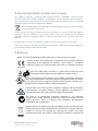
7_3 Environment (WEEE, Batteries and Packaging) .......................................... 25
7_4 Marking ........................................................................................................ 25

4/28 Lane/7000 / 90002783 R11 000 01
Copyright © 2014 Ingenico / All rights reserved
1_Introduction
Thank you for choosing an Ingenico payment terminal.
We recommend you to read carefully this user guide: it gives you the necessary information about
safety precautions, unpacking, installation and maintenance of your terminal.
WARRANTY / SECURITY
To benefit from the guarantee-related product, and to respect the security, we ask you to
use only the power supply delivered in box with the product, entrusting maintenance
operations only to an authorized person.
Failure to comply with these instructions will void the manufacturer’s responsibility.
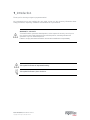
This symbol indicates an important Warning.
This symbol indicates a piece of advice.

5/28 Lane/7000 / 90002783 R11 000 01
Copyright © 2014 Ingenico / All rights reserved
2_Unpacking
According to the model, the following items are included in the packaging box (including optional
accessories):
The terminal
The box may also include the following items depending on your working configuration:
An installation guide
Cable (specific to connectivity requirements)
Power supply unit and power cord
A stylus
Modules
Screws to fix the main cable and the module
CAUTION
The power supply unit provided with your equipment is specially designed for it. Do not use
any other power supply.
ADVICE
Keep the packaging. It must be re-used whenever the terminal is shipped.

6/28 Lane/7000 / 90002783 R11 000 01
Copyright © 2014 Ingenico / All rights reserved
3_Recommendations
3_1 Safety
Power on/Power down – Emergency stop
To power on or power down the terminal, connect or disconnect the power supply from the electric
outlet.
Power supply unit
CAUTION
Only use the power supply AC/DC provided with Lane/7000 or the power provided by a cash
register limited power source (LPS).
Authorized power supply units:
Desktop Power Supply units have to be connected to the mains with one of these cables:
- Power cord 189609046 (EU)
- Power cord 188413214 (US)
CAUTION
Lithium battery cell
The terminal is fitted with a lithium battery cell which is not accessible to the user. Only a
qualified technician is authorized to open the unit and change this component.
Risk of explosion if the battery is replaced by an incorrect type. Dispose of used battery
according to the instructions.
Electrical power supply network
The electrical outlet must meet the following criteria:
Must be installed near the equipment and easily accessible;
Must meet standards and regulations in the country of use.
Explosion areas
Certain regulations restrict the use of radio equipment in chemical plants, fuel depots and any site
where blasting is carried out. You are urged to comply with these regulations. The terminal shall be
protected by a specially fitted and certified cover enabling use in proximity to a fuel pump.
Connection of headset on audio jack
Power Supply Unit Supplier
Type
Supplier reference
Electrical
characteristics
Ingenico
part number
PHIHONG TECHNOLOGY
Co. Ltd
Desktop
PSM24W-080L6IN-R
8VDC 3A
Level VI
296198809
PHIHONG TECHNOLOGY
Co. Ltd
Wallplug
PSC16E-080L6IN-R
PSC16A-080L6IN-R
8VDC 2A
Level VI
296199611
296196003

7/28 Lane/7000 / 90002783 R11 000 01
Copyright © 2014 Ingenico / All rights reserved
CAUTION
An excessive acoustic pressure of headset can involve deafness!
3_2 Security of your terminal (tampering attempt detection)
Your device fulfils current applicable PCI PTS security requirements.
Upon receipt of your terminal you should check for signs of tampering of the equipment. It is strongly
advised that these checks are performed regularly after receipt. You should check, for example: that
the keypad is firmly in place; that there is no evidence of unusual wires that have been connected to
any ports on your terminal or associated equipment, the chip card reader or any other part of your
terminal. Such checks would provide warning of any unauthorised modifications to your terminal, and
other suspicious behaviour of individuals that have access to your terminal.
Your terminal detects any “tampered state”. In this state the terminal will repeatedly flash the
message” Alert Irruption!” and further use of the terminal will not be possible. If you observe the “Alert
Irruption!” message, you should contact the terminal helpdesk immediately.
You are strongly advised to ensure that privileged access to your terminal is only granted to staff that
have been independently verified as being trustworthy.
The terminal must never be put in or left at a location where it could be stolen or replaced by another
device.
WARNING
If the warranty label is torn or removed, the warranty will be void.
CAUTION
Positioning of the Lane/7000 on check stand must be in such a way to make cardholder PIN
(Personal Identification Number) spying infeasible.
Installing device on an adjustable stand must be in such a way that consumers can swivel
the terminal sideways and/or tilt it forwards/backwards to a position that makes visual
observation of the PIN-entry process difficult.
Positioning of in-store security cameras such that the PIN-entry keypad is not visible.
NEVER ask the customer to divulge their PIN Code. Customers should be advised to
ensure that they are not being overlooked when entering their PIN Code.
Warranty label
(on the bottom side of
the terminal)

8/28 Lane/7000 / 90002783 R11 000 01
Copyright © 2014 Ingenico / All rights reserved
CAUTION
This equipment may not be modified, altered or changed in any way without signed written
permission from Ingenico

9/28 Lane/7000 / 90002783 R11 000 01
Copyright © 2014 Ingenico / All rights reserved
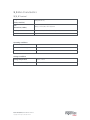
3_3 Main Characteristics
3_3_1 Terminal
Weight
(Poids, Gewicht)
583g (20.56 oz)
Size
(dimensions, Maße)
181 (L) x 152 (W) x 35.2 (H) mm
Display
5” backlit LCD, WVGA (800 x 480 pixels)
Touchscreen
Capacitive
Operating conditions
Ambient temperature
from 0°C to +45°C
Max relative humidity
85% RH non-condensing at +40°C
Max altitude
2000 m
Storage conditions
Storage temperature
-20°C, +55°C
Max relative humidity
85% at +55°C

10/28 Lane/7000 / 90002783 R11 000 01
Copyright © 2014 Ingenico / All rights reserved
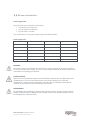
3_3_2 Power characteristics
Power supply units
The Lane/7000 can be powered by several ways:
An external power supply unit
By POE (Power over Ethernet)
By USB (5VDC or 12VDC)
The characteristics for each type of power supply are detailed hereafter.
Power supply unit
296198809
296199611
296196003
Model Name
PSM24W-080L6IN-R
PSC16E-080L6IN-R
PSC16A-080L6IN-R
Weight
243 g (8.57 oz)
160g (5.6 oz)
160g (5.6 oz)
Size (l x w x h)
120 x 50 x 31 mm
74 x 35 x 46.2 mm
74 x 35 x 46.2 mm
Class
Level VI
Level VI
Level VI
Input voltage
AC 100-240V 50-60Hz
AC 100-240V 50-60Hz
AC 100-240V 50-60Hz
Output voltage
DC 8V 3A
DC 8V 2A
DC 8V 2A
WARNING
The power supply unit provided with your equipment is specially designed for this Ingenico terminal.
Do not use any other power supply. The use of a power supply with apparently similar voltage/current
characteristics may damage your terminal.
AVERTISSEMENT
Dans le cas où vous choisiriez d’utiliser un bloc alimentation, assurez-vous de n’utiliser que le bloc
d'alimentation qui a été conçu spécialement pour votre terminal. N'utilisez pas d'autre bloc
d'alimentation. L'emploi d'un bloc d'alimentation présentant des caractéristiques apparemment
similaires de tension/intensité peut endommager votre terminal.
WARNHINWEIS
Nur das Netzteil, das speziell für Ihr Gerät ausgelegt wurde, benutzen. Benutzen Sie kein anderes
Netzteil. Die Benutzung eines Netzgeräts mit scheinbar ähnlicher Spannung/Stromstärke kann zur
Beschädigung Ihres Terminals führen.

11/28 Lane/7000 / 90002783 R11 000 01
Copyright © 2014 Ingenico / All rights reserved
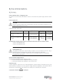
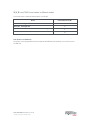
3_3_3 Lane/7000 Power values in different modes
Lane/7000 works at voltages between 8VDC and 12VDC.
Mode
Lane/7000 Power (W)
Idle mode - backlight OFF
3
Idle mode - backlight ON
3.7
Typical – smartcard and contactless in test - Backlight ON
5
Maximum (+2 Loads of 2.5W each)
12
POE (Power over Ethernet)
The power sourcing equipment must be compliant with IEEE802.3af standard, class 0 which means
12.95W max.

12/28 Lane/7000 / 90002783 R11 000 01
Copyright © 2014 Ingenico / All rights reserved
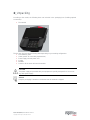
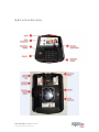
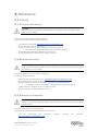
3_4 Functional description

13/28 Lane/7000 / 90002783 R11 000 01
Copyright © 2014 Ingenico / All rights reserved
3_5 Installation & Connections
3_5_1 Positioning the terminal
Place the terminal with an easy access to an electrical outlet. Place the terminal away from any heat
source and protected from dust, vibrations and electromagnetic radiations (away from video terminals,
PC, anti-shoplifting barriers ...). The terminal is exclusively made for indoor use.
The Lane/7000 device may be mounted on a flat surface, wall, or customer stand.
CAUTION
Do not place the Lane/7000 device on a PC monitor, adjacent to an electronically active
security tag deactivation system, or near other sources of magnetic fields.
The Lane/7000 device must be at least 30 centimeters (12 inches) away from an electronically active
type of security tag deactivation pad.
There are two types of security tag deactivation systems:
An electronically active system sends out a powerful and potentially disruptive signal to deactivate
the security tag. If the Lane/7000 device is placed too close to the system’s pad, or placed above
the pad, the product may not work properly.
A passive system is a permanent magnet type that does not send out a signal. This type should
not affect the Lane/7000 device.
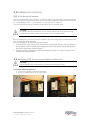
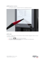
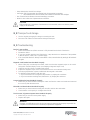
3_5_2 Inserting SAM (Secure access module) and Micro SD
CAUTION
Before starting, switch off the terminal by disconnecting the power supply.
Perform the following operations:
Unscrew the modules and remove them both
Access to SAM and Micro SD is now possible.

14/28 Lane/7000 / 90002783 R11 000 01
Copyright © 2014 Ingenico / All rights reserved
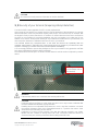
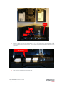
Insert the SAM Card into the slot marked (1), (2) or (3). Take care to ensure that the SAM
Card is inserted in the correct manner. The cut corner must be positioned as indicated on the
figure below.
Slide back the module and screw them tight

15/28 Lane/7000 / 90002783 R11 000 01
Copyright © 2014 Ingenico / All rights reserved
CAUTION
Do not use any tools when installing or removing the SAM Card or Micro SD.
WARNING
During this operation, it is necessary to be in an ESD protected environment. As this is not
very easy, it is recommended to make this operation using ESD shoes for example
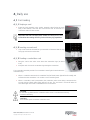
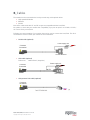
3_5_3 Connecting the terminal to the host
CAUTION
Connecting must be made when power supply unit is not plugged in the cable.

16/28 Lane/7000 / 90002783 R11 000 01
Copyright © 2014 Ingenico / All rights reserved
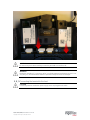
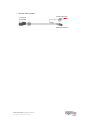
Flip the terminal. There is one port on the back for power and communications.
Connect the cable on the terminal.
Connect the other end to the power supply unit and a Host (PC / cash register…).
Plug the power supply into the mains.
WARNING
The main port at the back must not be used to connect an HDMI video cable.
Only connect cables provided by Ingenico.
Note: 2 screws can be added (M2.5 x 8) to hold more firmly the cable.
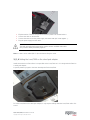
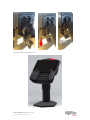
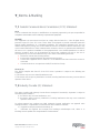
3_5_4 Setting the Lane/7000 on the stand pole adaptor
Install the terminal on a flat surface is not possible on the Lane/7000 as is. It is designed to be fitted on
a stand pole adaptor.
A specific pattern by Ingenico has been developed to fit the lane/7000.
To fit the Lane/7000 to the stand pole adaptor, it only requires sliding down the Lane/7000 until a click
sound:

17/28 Lane/7000 / 90002783 R11 000 01
Copyright © 2014 Ingenico / All rights reserved
The Lane/7000 is now ready to use:

18/28 Lane/7000 / 90002783 R11 000 01
Copyright © 2014 Ingenico / All rights reserved
4_Daily use
4_1 Card reading
4_1_1 Swiping a card
Insert the card manually in the reader, magnetic stripe facing the main
body of the terminal, and slide the card from the rear to the front in a
continuous motion for best results.
Swipe the card with constant speed, neither too slowly nor too fast,
to maximize the reading efficiency and avoid annoying repetitions.
4_1_2 Inserting a smart card
Chip cards should be inserted into your terminal as illustrated with the chip
facing up and into the card reader.
4_1_3 Reading a contactless card
Bring the card to the active zone above the contactless logo (at about
1cm).
Keep the card close to the contactless logo during the transaction.
Your contactless terminal provides four contactless status lights located above the
contactless logo.
When a contactless transaction is started the first (left hand) status light will be lit steadily; this
indicates that the contactless is in use but a card is not being read.
When a contactless card is presented to the contactless active zone during a transaction the
second, third and fourth status lights will be lit in turn. The card read is successful when all
four status lights are lit and a confirmation tone can be heard.
CAUTION
Do not stick any label onto the contactless active zone. It can decrease seriously
contactless efficiency.
CAUTION
Avoid metallic parts around the contactless area.

19/28 Lane/7000 / 90002783 R11 000 01
Copyright © 2014 Ingenico / All rights reserved
4_2 Signature capture
The signature capture is done with a stylus and a capacitive touchscreen
4_3 Audio
A speaker is available there is also an Audio jack. When a headset is plugged in, there is no more
sound from the speaker
The audio jack is located next to the card reader.
This option is not designed to play music, but to facilitate the use by blind people.
The jack is 3.5mm, 32 ohms impedance.

20/28 Lane/7000 / 90002783 R11 000 01
Copyright © 2014 Ingenico / All rights reserved
5_Maintenance
5_1 Cleaning
5_1_1 Cleaning of the terminal
CAUTION
Before making any operations of maintenance in the terminal, make sure that the power
supply is disconnected.
First of all, unplug all the wires from the terminal.
Good rules for proper cleaning of the terminal are:
Use Ingenico Cleaning kit: http://www.ingenico.cleaningcards.com/
Do not clean the electrical connections.
Do not use in any case, solvents, detergents or abrasive products:
o Those materials might damage the plastic or electrical contacts.
Avoid exposing the terminal to the direct rays of the sun.
Do not put anything into the slot of the smart card reader
5_1_2 Entretien du terminal
ATTENTION
Assurez-vous que tous les câbles sont bien débranchés du terminal avant toute intervention
de maintenance sur le terminal
Avant tout, débranchez tous les câbles du terminal.
Pour bien nettoyer le terminal :
Utilisez les kits de nettoyage Ingenico : http://www.ingenico.cleaningcards.com/
Ne nettoyez pas les connexions électriques.
N'utilisez jamais de solvants, de détergents, d’alcool ou de produits abrasifs :
o Ces produits peuvent endommager le plastique ou les contacts électriques.
Evitez d'exposer le terminal aux rayons directs du soleil.
N'insérez rien dans la fente du lecteur de carte.
5_1_3 Wartung von Endgeräten
ACHTUNG
Stellen Sie vor jeglicher Wartungsarbeit an dem Terminal sicher, dass die Stromversorgung
unterbrochen ist
Als erstes alle Kabel vom Terminal trennen.
Regeln für eine ordnungsgemässe Reinigung des Terminals:
Für die Außenseite des Terminals, Ingenico Cleaning kits benutzen:
http://www.ingenico.cleaningcards.com/
Seite wird geladen ...
Seite wird geladen ...
Seite wird geladen ...
Seite wird geladen ...
Seite wird geladen ...
Seite wird geladen ...
Seite wird geladen ...
Seite wird geladen ...
-
 1
1
-
 2
2
-
 3
3
-
 4
4
-
 5
5
-
 6
6
-
 7
7
-
 8
8
-
 9
9
-
 10
10
-
 11
11
-
 12
12
-
 13
13
-
 14
14
-
 15
15
-
 16
16
-
 17
17
-
 18
18
-
 19
19
-
 20
20
-
 21
21
-
 22
22
-
 23
23
-
 24
24
-
 25
25
-
 26
26
-
 27
27
-
 28
28


Ingeni XKB-L7000CL Benutzerhandbuch
- Typ
- Benutzerhandbuch
- Dieses Handbuch eignet sich auch für
in anderen Sprachen
- English: Ingeni XKB-L7000CL User manual
Verwandte Artikel
Andere Dokumente
-
Ingenico ISMP3- Benutzerhandbuch
-
Ingenico OPEN1500 Installationsanleitung
-
-
Ingenico OPEN2500 Quick Start And Installation Manual
-
-
Ingenico Self 4000 Benutzerhandbuch
-
Ingenico Self 5000 Archives Common SECC Benutzerhandbuch
-
-
Ingenico Self-5000 Benutzerhandbuch
-
Acer DA221HQL Schnellstartanleitung