Gemini Stereo System XL-500II Benutzerhandbuch
- Kategorie
- Drehscheibe
- Typ
- Benutzerhandbuch
Dieses Handbuch eignet sich auch für

(1)
OPERATIONS MANUAL
BEDIENUNGSHANDBUCH
MANUAL DEL OPERADOR
MANUEL D’INSTRUCTIONS
XL-500 II
DIRECT-DRIVE MANUAL TURNTABLE
HANDDREHSCHEIBE MIT DIREKTANTRIEB
GIRADISCOS MANUAL DE ACCIONAMIENTO DIRECTO
TABLE TOURNANTE MANUELLE À ENTRAÎNEMENT DIRECT
MULTI LANGUAGE INSTRUCTIONS:
English......................................................................................................Page 4
Deutsch.....................................................................................................Page 6
Español.....................................................................................................Page 8
Francais.................................................................................................Page 10

(2)
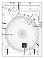
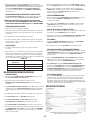
Figure 1
16
10
21
7
17
4
1
9
5
18
19
14132322
11
6
20
15
2
3
12
8

(3)
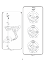
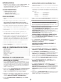
Figure 2
Figure 3

(4)
1. Connect the lead wires to the cartridge terminals. For your convenience,
the terminals of most cartridges are color coded. Connect each lead
wire to the terminal of the same color.
White (L+).................................Left Channel +
Blue (L-)....................................Left Channel -
Red (R+)................................Right Channel +
Green (R-).............................Right Channel -
2. Mount the cartridge in the HEADSHELL (5) and tighten it with the
screws included with the cartridge.
ATTENTION STANTON 680 CARTRIDGE USERS
When using a Stanton 680 or similar cartridge, where the body
is grounded to a cartridge terminal, remove the grounding strap
from the cartridge body to the cartridge ground terminal. Failure
to do this may result in excessive hum.
HEADSHELL INSTALLATION:
Insert the HEADSHELL (5) into the front of the tubular TONE ARM (6).
While holding the HEADSHELL (5) firmly in a horizontal position, turn the
LOCKING NUT (7) counter clockwise until the HEADSHELL (5) is locked
in place.
COUNTERWEIGHT INSTALLATION: (SEE FIG. 3)
1. Slide the COUNTERWEIGHT (8) onto the rear of the TONE ARM (6) with
the numbered stylus gauge facing forward.
2. Twist the COUNTERWEIGHT (8) lightly counter clockwise, to screw it
onto the rear of the TONE ARM (6)
.
ADJUSTING HORIZONTAL ZERO (0) BALANCE AND
STYLUS PRESSURE:
1. Without touching the stylus tip, remove the stylus protector (if your
cartridge has a detachable one).
2. Release the ARM CLAMP (9) and lift the TONE ARM (6) off the ARM
REST (10).
3. Counter clockwise advancement of the COUNTERWEIGHT (8) will
cause the cartridge side of the TONE ARM (6) to be lowered. Clockwise
will cause the opposite. Turn the COUNTERWEIGHT clockwise or
counter clockwise as needed until the TONE ARM is balanced
horizontally. You can easily tell this by watching for the point where the
TONE ARM “floats” freely.
4. Place TONE ARM (6) on ARM REST (10) and lock it in place with the
ARM CLAMP (9).
5. With the TONE ARM (6) locked on the ARM REST (10), hold the
COUNTERWEIGHT (8) steady with one hand while rotating the STYLUS
PRESSURE RING (11) until the numeral “0” on the ring aligns with the
center line on the TONE ARM (6) rear shaft. The horizontal zero (0)
balance should be completed.
6. Refloat the TONE ARM to ensure horizontal zero (0) balance. If zero
balance has not been maintained, repeat counterweight steps 3 - 5.
7. After adjusting the horizontal zero (0) balance, turn the balanced
COUNTERWEIGHT (8) counter clockwise until the cartridge
manufacturer’s recommend stylus pressure appears on the STYLUS
PRESSURE RING (11) where it meets the center line of the TONE ARM
(6) rear shaft.
ADJUSTING THE ANTI-SKATING CONTROL:
Set the ANTI-SKATING CONTROL (12) to the same value as the stylus
pressure.
NOTE: IF YOUR TURNTABLE CAME WITH A CN-25 CARTRIDGE, IT
HAS A RECOMMENED TRACKING FORCE OF 3.0 GRAMS AND
CAN HAVE RANGE FROM 2.5-3.5 GRAMS.
INSTALLING THE DUSTCOVER:
1. Mount the hinges onto the dustcover.
INTRODUCTION:
Congratulations on purchasing a Gemini XL-500 II turntable. This state
of the art turntable includes the latest features. Prior to use, we suggest
that you carefully read all the instructions.
FEATURES:
• ±10% Pitch control
• Braking for quick stops
• Strobe illuminator
• Soft-touch start/stop switch
PRECAUTIONS:
1. Read all operating instructions before using this equipment.
2. To reduce the risk of electrical shock, do not open the unit.
There are NO USER REPLACEABLE PARTS INSIDE.
Please contact the Gemini Service Department or your authorized dealer
to speak to a qualified service technician.
In the U.S.A., if you have any problems with this unit, call 1-732-969-9000
for customer service. Do not return equipment to your dealer.
3. Tone Arm bearings are factory set and sealed. Any attempt at
adjustment will void the warranty.
4. Be sure that all AC power is OFF while making connections.
5. Cables should be low capacitance, shielded and of proper length. Make
sure that all plugs and jacks are tight and properly connected.
6. Always begin with the audio level faders/volume controls set at
minimum and the speaker volume control(s) set to OFF. Wait 8 to 10
seconds prior to turning up the speaker volume to prevent the transient
“POP” that could result in speaker/crossover damage.
7. DO NOT EXPOSE THIS UNIT TO RAIN OR MOISTURE.
8. DO NOT USE ANY SPRAY CLEANER OR LUBRICANT ON ANY
CONTROLS OR SWITCHES.
PARTS CHECKLIST:
Turntable unit.............................................................................................1
Dust cover hinge.......................................................................................2
Turntable platter.........................................................................................1
45 RPM adapter.........................................................................................1
Rubber mat................................................................................................1
Counter balance........................................................................................1
Dust cover.................................................................................................1
Headshell...................................................................................................1
ASSEMBLY AND SET-UP:
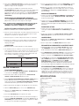
SEE FIG. 1 FOR PART NUMBERS AND LOCATIONS.
TURNTABLE INSTALLATION:
1. Set the TURNTABLE BASE (1) on a flat, level surface free of vibration.
Try to place the unit as far away from the speakers as possible. Keep
the unit away from direct exposure to the sun, heat, moisture or dirt.
Keep the unit well ventilated. Use the turntable feet to horizontally
stabilize the unit.
2. Make sure that the VOLTAGE SELECTOR (3) switch (located on the
TURNTABLE BASE) is set to the correct voltage. WARNING: If you try to
operate the turntable with the incorrect voltage setting, it can damage
your turntable.
3. After checking to ensure that all packing materials have been removed,
gently place the PLATTER (2) on the center spindle of the TURNTABLE
BASE (1).
4. Put the RUBBER MAT (4) on the PLATTER (2).
CARTRIDGE INSTALLATION: (SEE FIG. 2)
Because all cartridges have their own designs, please refer to your
particular cartridge’s instructions to insure proper installation.

(5)
2. Hold the dustcover in position, directly above the turntable, and slide the
hinge bases into the holders mounted on the rear panel.
3. Always raise the dustcover before removal.
4. Avoid opening and closing the dustcover during play. Undesirable
vibration and stylus skipping can result.
CONNECTIONS:
1. Plug the AC power plug into an appropriate outlet.
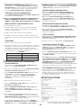
2. See Table A for proper connection of the output RCA plugs and ground
connector. Make sure that all the plugs are firmly plugged into the
appropriate jacks (phono inputs). To reduce hum, make sure the ground
lug is firmly connected to the ground screw.
TABLE A
OPERATING INSTRUCTIONS:
BASIC OPERATION:
1. Place a record on the RUBBER MAT (4) which sits on the PLATTER (2).
2. Select the desired speed by depressing the 33 or 45 SPEED SELECTOR
(15) button.
3. Turn the POWER (13) switch to the “ON” position, at which point the
strobe illuminator (built into the POWER (13) switch and the speed
indicator (for the selected speed) will illuminate.
4. Remove the stylus protector (if applicable to your cartridge).
5. Release the ARM CLAMP (9) found on the ARM REST (10).
6. Push the START STOP (14) button. The turntable PLATTER (2) will start
to spin.
7. Push the CUE LEVER (16) to the “UP” position.
8. Position the tone arm over the desired position on the record and push
the CUE LEVER to the “DOWN” position. The TONE ARM (6) will slowly
lower onto the record at which time play will begin.
9. When play is over, raise the TONE ARM (6), move it to the ARM REST
(10), and secure it with the ARM CLAMP (9).
10.You now have the option of turning off the power by turning the
POWER (13) switch to the “OFF” position, or stopping the PLATTER (2)
by pushing the START STOP (14) button and engaging the electronic
brake.
INTERRUPTING PLAY:
1. Pushing the CUE LEVER (16) to the “UP” position will cause the TONE
ARM (6) to lift stopping play.
2. Pushing the CUE LEVER (16) to the “DOWN” position will cause the
TONE ARM (6) to slowly lower onto the record at the point where play
was interrupted.
PLAYING 45 RPM RECORDS:
1. When playing a 45 RPM record with a large center hole, first place the
45 ADAPTER (17) on the center spindle.
2. Be sure that the 45 SPEED SELECTOR (15) button is pushed and the 45
speed indicator is illuminated.
TARGET LIGHT:
1. Push the TARGET LIGHT SWITCH (18) firmly and the TARGET LIGHT
(19) will illuminate the stylus tip.
2. When not being used, the TARGET LIGHT should be turned off.
ADJUSTING THE PITCH CONTROL:
1. The XL-500 II is equipped with a PITCH CONTROL (21). When the
PITCH CONTROL is in the center position the speed will be 33 or 45
depending on which SPEED SELECTOR (15) is pushed.
2. When the PITCH CONTROL is positioned off center, the pitch can vary
±10% depending on the position of the PITCH CONTROL.
3. The PLATTER (2) is equipped with a STROBE RPM INDICATOR STRIP
(22) and the POWER (13) switch contains built in STROBE LIGHTS (23).
When the PLATTER (2) is spinning, the STROBE LIGHTS illuminate the
STROBE RPM INDICATOR STRIP. At 60 Hz the bottom row of dots will
appear to be stationary when the speed of the platter is exactly 45 RPM
and the second row from the bottom will appear to be stationary at 33
RPM. At 50 Hz, the second row from the top represents 45 RPM and the
top row represents 33 RPM.
PITCH BEND:
1. Pushing the PITCH BEND (20) buttons will temporarily raise or lower the
pitch without changing the slide setting. Releasing the buttons will return
the pitch to the slide setting.
SPECIFICATIONS:
TURNTABLE SECTION:
Type..................................................................Direct Drive Manual Turntable
Drive Method.................................................................................Direct Drive
Motor................................................................................Brushless DC Motor
Platter....................................................Aluminum Diecast 13” (332 mm) Dia.
Speed...................................................................................33 1/3 or 45 RPM
Starting Torque.................................................................................1.2 Kg/cm
Build-up Characteristics................................0.8 sec. standstill to 33 1/3 RPM
Braking System.....................................................................Brake (Solenoid)
Wow and Flutter.......................................................................0.02% WRMS*
* This rating refers to the turntable assembly and platter only and excludes
effects of records, cartridges or tonearms.
Rumble................................................................................56 dB Unweighted
TONEARM SECTION:
Type.............................................................Universal S-Shaped Tubular Arm
Effective Length................................................................9 1/16” (230.1 mm)
Overhang..............................................................................19/32" (15.2 mm)
Effective Mass.............................................................9 g (Without Cartridge)
Offset Angle...............................................................................................22°
Friction.......................................................Less Than 7 mg (Lateral, Vertical)
Tracking Error Angle...................Within 2°32' at the outer groove and within
...........................................0°32' at the inner groove of a 30 cm (12") record
Stylus Pressure Adjust Range..............................................................0 - 5 g
Applicable Cartridge Weight Range.....................................................6 - 10 g
Headshell Weight.....................................................................................5.6 g
GENERAL:
Power Supply............................................................115V~60Hz/230V~50Hz
Power Consumption..........................................................................15 Watts
Dimensions.......................................17 3/4” x 6" x 14" (450 x 152 x 352 mm)
Weight...................................................................................22.5 lbs. (10 Kg)
SPECIFICATIONS ARE SUBJECT TO CHANGE WITHOUT NOTICE.
THE WEIGHT AND DIMENSIONS SHOWN ARE APPROXIMATE.
L (WHITE)
R (RED)
GND (Spade Lug)
MIXER OR RECEIVER
OUTPUT CONNECTORS
PHONO L CHANNEL
PHONO R CHANNEL
GND Screw

(6)
EINBAU DES TONABNEHMERS:
(SIEHE ABBILDUNG 2)
Weil alle Tonabnehmer individuell ausgeführt sind, siehe jeweilige
Anweisungen für Tonabnehmer, um richtigen Einbau sicherzustellen.
1. Die Zuleitungsdrähte an den Tonabnehmerklemmen anschlieen. Um den
Anschlu zu erleichtern, sind die meisten Tonabnehmerklemmen
farbkodiert. Die Zuleitungsdrähte an den Klemmen der jeweiligen
Farbkennzeichnung anschlieen.
Weiß (L+)..............................linker Kanal +
Blau (L-).................................linker Kanal -
Rot (R+)................................rechter Kanal +
Grün (R-)............................rechter Kanal -
2. Den Tonabnehmer in den TONKOPF - HEADSHELL (5) einbauen und mit
den dem Tonabnehmer beigefügten Schrauben befestigen.
WICHTIG FÜR ALLE ANWENDERDES STANTON 680TONABNEHMERS
Bei Anwendung eines Stanton oder ähnlichen Tonabnehmer, wo der
Körper an einer Tonabnehmerklemme geerdet ist, den Erdungsdraht
entfernen, der vom Körper des Tonabnehmers zur Erdungsklemme führt.
Nichtbeachtung dieser Manahme kann zu übermäigem Brummen führen.
EINBAU DES TONKOPFES:
Den TONKOPF - HEADSHELL (5) in der Vorderseite des röhrenförmigen
TONARMS - TONE ARM (6) einfügen. Beim Halten des TONKOPFES in
horizontaler Position die SICHERUNGSMUTTER - LOCKING NUT (7)
gegen den
Uhrzeigersinn drehen, bis der TONKOPF einrastet.
EINBAU DES BALANCEGEWICHTS: (SIEHE ABBILDUNG 3)
1. Das BALANCEGEWICHT - COUNTERWEIGHT (8) auf den hinteren Teil
des TONARMS - TONE ARM (6) Schieben, wobei die numerierte
Nadeldicke nach vorne gerichtet sein muss.
2. Das BALANCEGEWICHT - COUNTERWEIGHT (8) gering im
Gegenuhrzeigersinn ziehen, um es auf den hinteren Teil des
TONARMS - TONE ARM (6) zu schrauben.
HORIZONTALER NULLPUNKTABGLEICH UND
REGULIERUNG DES AUFLAGEDRUCKS:
1. Ohne die Nadelspitze zu berühren, entfernen Sie den Nadelschutz (falls
Ihr Tonabnehmer einen abnehmbaren Nadelschutz hat).
2. Die TONARM-KLEMMSCHELLE - ARM CLAMP (9) freigeben und den
TONARMS - TONE ARM (6) von der TONARMAUFLAGE - ARM REST
(10) abheben.
3. Durch das Verdrehen gegen den Uhrzeigersinn des
BALANCEGEWICHTS - COUNTERWEIGHT (8) wird die
Tonabnehmerseite des TONARMS - TONE ARM (6) gesenkt. Beim
Drehen im Uhrzeigersinn geschieht das Gegenteil. Das
BALANCEGEWICHT je nach Bedarf im oder gegen den Uhrzeigersinn
drehen, bis der TONARM horizontal ausbalanciert ist. Dies lässt sich
leicht feststellen, indem man die Stelle beobachtet, wo der TONARM
unbehindert “schwimmt”.
4. Den TONARMS - TONE ARM (6) auf die TONARMAUFLAGE - ARM
REST (10) setzen und ihn mit der TONARM-KLEMMSCHELLE - ARM
CLAMP (9) festklemmen.
5. Indem der TONARMS - TONE ARM (6) auf der TONARMAUFLAGE -
ARM REST (10) festgeklemmt ist, halten Sie das BALANCEGEWICHT -
COUNTERWEIGHT (8) ruhig mit der Hand, während Sie den
AUFLAGEDRUCKRING - STYLUS PRESSURE RING (11) rotieren, bis
sich die Ziffer "0" auf dem Ring mit der Mittellinie an der Hinterwelle des
TONARMS ausrichtet. Der horizontale Nullpunktabgleich (0) ist nun
abgeschlossen.
6. Den TONARM erneut schwimmen lassen, um sicherzustellen, da der
horizontale Nullpunktabgleich (0) beibehalten wird. Wird er nicht
beibehalten, wiederholen Sie Schritte 3 - 5.
EINLEITUNG:
Wir gratulieren Ihnen zum Kauf eines Gemini XL-500 II Plattenspielers.
Dieses hochentwickelte erstklassige Gerät enthält die neuesten
Leistungsmerkmale. Vor Anwendung dieses Plattenspielers bitte alle
Anweisungen sorgfältig durchlesen.
LEISTUNGSMERKMALE:
• ±10% Tonhöhenabstimmung
• Bremsvorrichtung für Schnellstop
• Strobelicht
• Start-/Stop-Funktionstaste
VORSICHTSMANAHMEN:
1. Vor Anwendung dieses Geräts bitten alle Anweisungen sorgfältig
durchlesen.
2. Das Gerät nicht öffnen, um das Risiko elektrischen Schocks zu mindern.
Es enthält KEINE VOM ANWENDER ERSETZBAREN TEILE. Die Wartung
darf nur von befähigten Wartungstechnikern durchgeführt werden.
3. Die Tonarmlager sind werkseingestellt und abgedichtet. Jegliche
Änderungsversuche machen die Garantie ungültig.
4. Darauf achten, da beim Anschlu die Wechseltromleistung abgeschaltet ist.
5. Nur kapazitätsarme, abgeschirmte Kabel vorschriftsmäiger Länge
benutzen. Darauf achten, da alle Stecker und Buchsen fest
angeschraubt und richtig angeschlossen sind.
6. Zu Beginn müssen die Tonpegelüberblender und Lautstärkenregler auf
Mindeststärke eingestellt und der (die) Lautstärkenregler in OFF-Position
geschaltet sein. Vor dem Lauterstellen 8 bis 10 Sekunden warten, um
den durch Einschwingung erzeugten Schroteffekt zu vermeiden, welches
zu Lautsprecher- und Frequenzweichenschaden führen könnte.
7. Dieses Gerät nicht Regen oder Feuchtigkeit aussetzen.
8. An den Reglern oder Schaltern kein Spray-Reinigungsmittel oder
Schmiermittel benutzen.
TEILE-CHECKLIST:
Plattenspieler.............................................................................................1
Plattenteller................................................................................................1
Gummiteller................................................................................................1
Abdeckhaube............................................................................................1
Abdeckhaubenscharnier...........................................................................2
45-U/min-Adapter......................................................................................1
Balancegewicht........................................................................................1
Tonkopf......................................................................................................1
ZUSAMMENBAU UND ANORDNUNG:
SIEHE ABBILDUNG 1 FüR TEILENUMMERN UND POSITIONEN.
EINBAU DES PLATTENSPIELERS:
1. Setzen Sie das PLATTENSPIELERCHASSIS - TURNTABLE BASE (1)
auf eine flache, ebene Fläche ohne Vibration. Das Gerät so weit wie
möglich von den Lautsprechern entfernt aufstellen. Das Gerät von
direktem Sonnenlicht, Wärme, Feuchtigkeit oder Schmutz fernhalten. Das
Gerät in gut belüfteter Umgebung aufstellen. Es mit den Plattentellerfüen
horizontal lagefest machen.
2. Den SPANNUNGSWAHLER - VOLTAGE SELECTOR (3) (befindet sich
auf dem PLATTENSPIELERCHASSIS) auf der richtigen Spannung
setzen. WARNUNG: Lassen Sie den PLATTENSPIELER rotieren mit einer
falschen Spannungseinstellung, dann kann der Plattenspieler sich
beschädigen.
3. Nachdem Sie überprüft haben, da das Verpackungsmaterial vollkommen
entfernt worden ist, setzen Sie den PLATTENTELLER - PLATTER (2)
vorsichtig auf die mittige Spindel des PLATTENSPIELERCHASSIS -
TURNTABLE BASE (1).
4. Den GUMMITELLER - RUBBER MAT (4) auf den PLATTENTELLER -
PLATTER (2) legen.

(7)
7. Nach dem horizontalen NULLPUNKTABGLEICH das abgeglichene
BALANCEGEWICHT - COUNTERWEIGHT (8) gegen den Uhrzeigersinn
drehen, bis der vom Tonabnehmerhersteller empfohlene Auflagedruck
auf dem AUFLAGEDRUCKRING - STYLUS PRESSURE RING (11)
erscheint, wo er mit der Mittellinie des TONARMS - TONE ARM (6)
zusammentrifft.
REGULIERUNG DER ANTISKATING-VORRICHTUNG:
Die ANTI-SKATING CONTROL (12) auf den gleichen Wert wie den
Auflagedruck einstellen.
ANMERKUNG: DIE CN- 25 PATRONE, DIE MIT DER
ANMERKUNG: WENN IHRE DREHSCHEIBE MIT EINER PATRONE
CN-25 KAM, HAT SIE EIN RECOMMENED, KRAFT VON 3,0 GRAMM
AUFZUSPÜREN UND KANN STRECKE VON 2,5-3,5 GRAMM HABEN.
EINBAU DER ABDECKHAUBE:
1. Die Scharniere an der Schutzhülle anbringen.
2. Halten Sie die Abdeckhaube direkt über dem Plattenteller in Position und
schieben die Scharniersockel in die Halterungen, die in die Rückwand
montiert sind.
3. Vor dem Entfernen immer die Abdeckhaube anheben.
4. Es sollte vermieden werden, die Abdeckhaube während des Spielens
zu öffnen und zu schlieen. Dies könnte zu unerwünschten Vibrationen
und Nadelspringen führen.
ANSCHLÜSSE:
1. Den Gleichstromleistungsstecker an einer geeigneten Buchse
anschlieen.
2. Siehe Tabelle A für vorschriftsmä ige Anschlüsse der Ausgangs-RCA-
Stecker und des Erdungssteckers. Achten Sie darauf, da alle Stecker
an den richtigen Buchsen fest angeschlossen sind (Phono-Eingänge).
Um Brummtöne zu vermindern, ist darauf zu achten, da die Erdungsöse
fest an der Erdungsschraube angeschlossen ist.
TABELLE A
BEDIENUNGSANWEISUNGEN:
GRUNDBETRIEB:
1. Die Platte auf den GUMMITELLER - RUBBER MAT (4) legen, die auf
dem PLATTENTELLER - PLATTER (2) sitzt.
2. Die gewünschte Drehzahl auswählen, indem Sie an der
DREHZAHLTASTE - SPEED SELECTOR (15) entweder 33 oder 45
auswählen.
3. Den LEISTUNGSSCHALTER - POWER (13) in die “ON”-Position schalten,
woraufhin das (in den LEISTUNGSSCHALTER eingebaute) Strobelicht
und die drehzahlanzeige (für die ausgewählte Drehzahl) aufleuchten
wird.
4. Den Nadelschutz abnehmen (falls an Ihrem Tonabnehmer vorhanden).
5. Die ARM CLAMP (9) an der ARM REST (10) freigeben.
6. Die START STOP-TASTE - START STOP (14) drücken. Der
PLATTENTELLER - PLATTER (2) wird anfangen zu drehen.
7. Den CUEING-HEBEL - CUE LEVER (16) in die “UP”-Position schieben.
8. Den Tonarm über die gewünschte Rille auf der Platte positionieren, und
den CUEING-HEBEL in die “DOWN”-Position schieben. Der TONARMS -
TONE ARM (6) wird sich langsam auf die Platte senken, woraufhin die
Platte zu spielen beginnt.
9. Bei Beendigung des Spielens heben Sie den TONE ARM (6), schieben
ihn auf die ARM REST (10) und befestigen ihn mit der ARM CLAMP (9).
10.Nun haben Sie die Option, den Strom abzuschalten, indem Sie den
POWER (13) in die “OFF”-Position schalten, oder den PLATTER (2) zu
stoppen, indem Sie die START STOP (14) taste drücken und die
elektronische Bremse aktivieren.
SPIELUNTERBRECHUNG:
1. Durch das Schieben den CUEING-HEBEL - CUE LEVER (16) in die “UP”-
Position wird der TONARMS - TONE ARM (6) angehoben und
unterbricht das Spielen.
2. Das Schieben den CUE LEVER (16) in die “DOWN”- Position wird den
TONE ARM (6) langsam an der Stelle auf die Platte setzen, wo das
Spielen unterbrochen wurde.
DAS SPIELEN VON 45-U/MIN-PLATTEN:
1. Wenn Sie eine 45-U/min-Platte spielen, die ein groß Mittelloch hat, setzen
Sie zunächst einen 45 ADAPTER (17) auf die Spindel.
2. Darauf achten, da die 45-U/min-DREHZAHLTASTE - SPEED SELECTOR
(15) gedrückt ist und die 45-U/min-drehzahlanzeige aufleuchtet.
ZIELLAMPE:
1. Fest auf den TARGET LIGHT SWITCH (18) drücken und die ZIELLAMPE -
TARGET LIGHT (19) wird die Nadelspitze beleuchten.
2. Bei Nichtgebrauch sollte die ZIELLAMPE ausgeschaltet werden.
REGULIERUNG DER TONHÖHENABSTIMMUNG:
1. Der XL-500 II ist mit einem PITCH CONTROL (21) ausgerüstet. Wenn der
TONHÖHENREGLER in Mittenposition steht, liegt die Drehzahl in der Nähe
von 33 oder 45 U/min, je nachdem welche SPEED SELECTOR (15)
gedrückt wird.
2. Wenn der TONHÖHENREGLER - PITCH CONTROL (21) auerhalb der
Mittenposition steht, kann die Drehzahl zwischen +/- 10% schwanken,
abhängig von der Position des TONHÖHENREGLERS.
3. Der PLATTER (2) ist mit einem STROBE RPM INDICATOR STRIP (22)
ausgerüstet, und der POWER (13) enthält eingebaute STROBE LIGHTS (23).
Wenn sich der PLATTER (2) dreht, erleuchten die STROBELICHTER den
STROBE RPM INDICATOR STRIP. Die untere Punktereihe wird feststehend
erscheinen, wenn die Drehzahl genau 45 U/min ist. Die zweite Reihe von
unten wird bei einer Drehzahl von 33 U/ min feststehend erscheinen.
PITCH BEND-TASTEN:
1. Wenn die PITCH BEND (20) Tasten (geleitete Tonhöhenverschiebung)
gedrückt werden, wird die Tonhöhe automatische angehoben oder
gesenkt, ohne die Schiebeeinstellung zu verändern. Wenn die Tasten
freigegeben werden, kehrt für Tonhöhe zur Schiebereinstellung zurück. Sie
können diese Funktion benutzen, um die geleitete Tonhöhenverschiebung beim
Mischen von einem Song zum anderen anzupassen.
SPEZIFIKATIONEN:
PLATTENSPIELER:
Typ........................................................................................................................................Manueller Plattenspieler
Antriebsmethode.......................................................................................................................................Direktantrieb
Motor...........................................................................................................................Bürstenloser Gleichstrommotor
Plattenteller................................................................................................................Druckgu 332 mm Durchmesser
Drehzahl......................................................................................................................................33 1/3 oder 45 U/min
Anlaufmoment..............................................................................................................................................1,2 Kg/cm
Einschwingkenndaten.........................................................................................0,8 sec. Stillstand bis 33 1/3 U/min
Bremssystem.................................................................................................................................Bremse (Solenoid)
Tonhöhenschwankungen......................................................................................................................0,02% WRMS*
* Dieser Nennwert bezieht sich nur auf die Plattenspielermontage und auf den Plattenteller, ausschielich
Auswirkungen der Platten, Tonabnehmer oder Tonarme
Rumpeln...................................................................................................................................56 dB Fremdspannung
TONARM:
Typ....................................................................................................................S-förmiger röhrenartiger Universalarm
Nutzlänge.......................................................................................................................................230,1 mm (9 1/16”)
Überhang...........................................................................................................................................15,2 mm (19/32")
Effektive Masse.....................................................................................................................9 g (ohne Tonabnehmer)
Reibungswinkel........................................................................................................................................................22°
Reibung................................................................................................................Wenige als 7 mg (seitlich, vertikal)
Abtastfehlerwinkel........................................................und innerhalb von 0°32" an der Innenrille einer 30-cm-Platte
Auflagedruck-Einstellbereich.............................................................................................................................0 - 5 g
Anwendbarer Tonabnehmern-Gewichtsbereich................................................................................................6 - 10 g
Tonkopfgewicht.....................................................................................................................................................5,6 g
ALLGEMEINES:
Stromversorgung....................................................................................................................115V~60Hz/230V~50Hz
Stromverbrauch....................................................................................................................................................15 W
Abmessungen.............................................................................................................................450 x 152 x 352 mm
Gewicht...............................................................................................................................................................10 Kg
SPEZIFIKATIONEN KÖNNEN OHNE VORHERIGE ANMELDUNG GEÄNDERT WERDEN.
GEWICHTSANGABEN UND ABMESSUNGEN SIND ANNÄHERND.
L ( WEIß)
R (ROT)
ERDUNG (Flachöse)
MIXER ODER RECEIVER
AUSGANGS-
ANSCHLUSS
PHONO- L KANAL
PHONO- R KANAL
Erdungsschraube

(8)
INTRODUCCIÓN:
Felicitaciones por su compra de un tocadiscos Gemini XL-500 II. Este
tocadiscos de la más avanzada tecnología está dotado de
características ultramodernas. Antes de usarlo, le recomendamos leer
cuidadosamente todas las instrucciones.
CARACTERÍSTICAS:
• Regulación del tono de ±10%
• Frenado para paradas rápidas
• Iluminador estroboscópico
• Interruptor táctil de arranque/parada
PRECAUCIONES:
1. Deberán leerse todas las instrucciones de operación antes de usar el
equipo.
2. Para reducir el riesgo de shock eléctrico, no abra la unidad.
NO CONTIENE PIEZAS REEMPLAZABLES POR EL USUARIO.
Sírvase comunicarse con el Departamento de Servicio Gemini o su
distribuidor autorizado y hablar con un técnico de servicio calificado.
3. Los cojinetes del brazo de fonocaptor están ajustados y sellados en
fábrica. Cualquier intento de ajuste dejará sin efecto la garantía.
4. Cerciórese de que toda la corriente CA esté APAGADA para efectuar
las conexiones.
5. Los cables deberán ser de baja capacidad, reguardados, y de
apropiado longitud. Cerciórese de que todos los enchufes y jacks
estén apretados y debidamente conectados.
6. Comience siempre con los atenuadores de nivel de audio/control de
volumen fijados en el nivel mínimo y el control de volumen de los
altoparlantes fijados en APAGADO. Espere 8 a 10 segundos antes de
aumentar el volumen de los altoparlantes para evitar el “chasquido”
transitorio que podría ocasionar daños a los altoparlantes/de cruce.
7. No deje esta unidad expuesta a lluvia o humedad.
8. No use ningun limpiador de rocío o lubricante en cuaquiera de los
controles o interruptores.
LISTA DE COMPROBACIÓN DE PIEZAS:
Unidad de tocadisco..................................................................................1
Plato del tocadisco....................................................................................1
Estera de goma.........................................................................................1
Tapa contra polvo......................................................................................1
Bisagra de tapa contra polvo....................................................................2
Adaptador de 45 RPM...............................................................................1
Contrapeso................................................................................................1
Portafonocaptor.........................................................................................1
MONTAJE Y CONFIGURACIÓN:
NOTA: VÉASE LA FIG. 1 PARA NÚMEROS DE PIEZA Y UBICACIONES.
INSTALACIÓN DEL TOCADISCO:
1. Ponga la BASE DEL TOCADISCO - TURNTABLE BASE (1) sobre una
superficie plana y nivelada sin vibraciones. Trate de colocar la unidad
lo mas alejado posible de los altoparlantes. Mantenga la unidad alejada
de la exposición directa del Sol, calor, humedad o suciedad. Mantenga
la unidad bien ventilada. Use la patas del tocadisco para estabilizar la
unidad en sentido horizontal.
2. Cerciórese de que el SELECTOR DE VOLTAJE - VOLTAGE SELECTOR
(3) (colocado en la BASE DEL TOCADISCO) esté arreglado para el
voltaje correcto. ADVERTENCIA: Si trata de hacer funcionar el
tocadisco con el voltaje incorrecto, corre el riesgo de dañarlo.
3. Después de comprobar que se hayan quitado todos los materiales de
embalaje, coloque el PLATO - PLATTER (2) suavemente en el huso
central de la BASE DEL TOCADISCO - TURNTABLE BASE (1).
4. Coloque la ESTERA DE GOMA - RUBBER MAT (4) sobre el PLATO -
PLATTER (2).
INSTALACIÓN DEL CARTUCHO: (VÉASE LA FIG. 2)
Debido a que todos los cartuchos son de diseño distinto, sírvase
referirse a las instrucciones de su cartucho específico, para garantizar
la instalación correcta.
1. Conecte los alambres conductores a los terminales del cartucho. Para
su conveniencia, los terminales de la mayoría de los cartuchos están
codificados por colores. Conecte cada alambre conductor al terminal del
mismo color.
Blanco (I+).....................Canal izquierdo +
Azul (I-).........................Canal izquierdo -
Rojo (D+)......................Canal derecho +
Verde (D-).....................Canal derecho -
2. Monte el cartucho dentro del PORTAFONOCAPTOR - HEADSHELL (5) y
apriételo con los tornillos incluidos con el cartucho.
ATENCIÓN USADORES DE LOS CARTUCHOSSTANTON 680
Al usar un cartucho Stanton 680 o cartucho similar, en el cual el cuerpo
se conectado a tierra a un terminal del cartucho, quite la correa de tierra
del cuerpo del cartucho hacia el terminal de tierra del cartucho. Al no
hacer esto puede resultar en zumbido excesivo.
INSTALACIÓN DEL PORTAFONOCAPTOR:
Inserte el PORTAFONOCAPTOR - HEADSHELL (5) en la parte delantera
del BRAZO DE FONOCAPTOR - TONE ARM (6) tubular. Sosteniendo el
PORTAFONOCAPTOR firmemente en posición horizontal, gire la
TUERCA FIADORA - LOCKING NUT (7) hacia la izquierda hasta que el
PORTAFONOCAPTOR se haya asegurado en posición.
INSTALACIÓN DEL CONTRAPESO: (VÉASE LA FIG. 3)
1. Deslice el CONTRAPESO - COUNTERWEIGHT (8) sobre la parte
posterior del BRAZO DE FONOCAPTOR - TONE ARM (6) con la medida
de la aguja numerada hacia el frente.
2. Gire el CONTRAPESO - COUNTERWEIGHT (8) ligeramente hacia la
izquierda para enroscarlo en la parte posterior del BRAZO DE
FONOCAPTOR - TONE ARM (6).
AJUSTE DEL EQUILIBRIO CERO (0) HORIZONTAL Y
PRESIÓN DE LA AGUJA:
1. Sin tocar la punta de la aguja, quite el protector de aguja (si el de su
cartucho es removible).
2. Suelte el SUJETABRAZO - ARM CLAMP (9) y levante el BRAZO DE
FONOCAPTOR - TONE ARM (6) del DESCANSILLO - ARM REST (10).
3. Si el CONTRAPESO - COUNTERWEIGHT (8) se avanza hacia la
izquierda, se bajará el lado del cartucho del BRAZO DE FONOCAPTOR -
TONE ARM (6). Si el CONTRAPESO se avanza hacia la derecha
ocurrirá lo contrario. Gire el CONTRAPESO hacia la derecha o la
izquierda según sea necesario hasta que el BRAZO DE FONOCAPTOR
esté horizontalmente equilibrado. Ese equilibrio es fácil de determinar;
espere el punto en que el BRAZO DE FONOCAPTOR “flote” libremente.
4. Coloque el BRAZO DE FONOCAPTOR - TONE ARM (6) sobre el
DESCANSILLO - ARM REST (10) y asegurelo en posición con el
SUJETABRAZO - ARM CLAMP (9).
5. Con el BRAZO DE FONOCAPTOR - TONE ARM (6) enganchado en el
DESCANSILLO - ARM REST (10), sostenga el CONTRAPESO -
COUNTERWEIGHT (8) en una mano y gire el ANILLO DE PRESIÓN DEL
ESTILETE - STYLUS PRESSURE RING (11) hasta que el número “0” en
el anillo se alinee con la línea central del eje trasero del BRAZO DE
FONOCAPTOR. El equilibrio horizontal en cero (0) deberá quedar
completo.
6. Flote de nuevo el BRAZO FONOCAPTOR para asegurarse que se haya
obtenido el equilibro horizontal en cero (0). Si no se ha mantenido este
equilibrio, repita los pasos de contrapeso 3 al 5.

(9)
7. Después de ajustar el equilibrio cero (0) horizontal, gire el
CONTRAPESO - COUNTERWEIGHT (8) equilibrado hacia la izquierda
hasta que aparezca en el ARO DE PRESIÓN DE AGUJA - STYLUS
PRESSURE RING (11) la presión de aguja recomendada del fabricante
del cartucho en el punto donde coincide con la línea central del eje
posterior del BRAZO DE FONOCAPTOR - TONE ARM (6).
AJUSTE DEL CONTROL ANTIDESLIZANTE:
Fije el CONTROL ANTIDESLIZANTE - ANTI-SKATING CONTROL (12) al
mismo valor que la presión de la aguja.
NOTA: SI SU PLACA GIRATORIA VINO CON UN CARTUCHO CN-25,
TIENE UN RECOMMENED EL SEGUIR DE LA FUERZA DE 3,0
GRAMOS Y PUEDE TENER GAMA A PARTIR DE 2,5-3,5 GRAMOS.
INSTALACIÓN DE LA TAPA CONTRA POLVOS:
1. Instale las bisagras en la cubierta.
2. Sostenga la tapa contra polvos en posición directamente arriba del
tocadisco y deslice las bases de las bisagras en los portabisagras
montados en el panel posterior.
3. Siempre levante la tapa contra polvos antes de quitarla.
4. Evite abrir y cerrar la tapa contra polvos cuando el tocadisco está en
funcionamiento, ya que podría ocurrir vibración indeseable y saltos de la
aguja.
CONEXIONES:
1. Conecte el enchufe CA en un tomacorriente apropiado.
2. Véase el Cuadro A para las conexiones apropiadas de los enchufes de
salida RCA y el conector a tierra. Cerciórese de que todos los enchufes
estén firmemente conectados en los jack apropiados (entradas
fonográficas). Para reducir el zumbido, cerciórese de que la orejeta a
tierra esté firmemente conectado al tornillo de tierra.
CUADRO A
INSTRUCCIONES DE OPERACIÓN:
OPERACIÓN BÁSICA:
1. Ponga un disco sobre la ESTERA DE GOMA - RUBBER MAT (4) que
descansa sobre el PLATO - PLATTER (2).
2. Seleccione la velocidad deseada, oprimiendo el BOTÓN SELECTOR DE
VELOCIDAD - SPEED SELECTOR (15) de 33 ó 45.
3. Ponga el INTERRUPTOR DE ENERGÍA - POWER (13) en la posición de
“ENCENDIDO”, en cuyo momento se encenderán el iluminador
estroboscópico (incorporado en el INTERRUPTOR DE ENERGÍA -
POWER (13) y el indicador de velocidad (para la velocidad
seleccionada).
4. Quite el protector de aguja (si se aplica a su cartucho).
5. Suelte el SUJETABRAZO - ARM CLAMP (9) que se encuentra en el
DESCANSILLO - ARM REST (10).
6. Oprima el BOTÓN DE ARRANQUE/PARADA - START STOP (14). El
PLATO - PLATTER (2) del tocadisco empezará a girar.
7. Oprima la PALANCA DE INDICACION - CUE LEVER (16) en la posición
de “ARRIBA”.
8. Sitúe el brazo de fonocaptor arriba del surco deseado en el disco y
ponga la PALANCA DE INDICACION en la posición de “ABAJO”. El
BRAZO DE FONOCAPTOR - TONE ARM (6) se bajará lentamente sobre
el disco en cuyo momento empezará a reproducir.
9. Una vez que haya terminado de reproducir, levante el BRAZO DE
FONOCAPTOR - TONE ARM (6), MUEVALO hacia el DESCANSILLO -
ARM REST (10) y fíjelo con el SUJETABRAZO - ARM CLAMP (9).
10.Ahora tiene la opción de apagar la unidad, pasando el INTERRUPTOR
DE ENERGÍA - POWER (13) a la posición de “APAGADO” o de detener el
PLATO - PLATTER (2), oprimiendo el BOTÓN DE ARRANQUE/PARADA
- START STOP (14) y enganchando el freno electrónico.
INTERRUPCIÓN DE LA REPRODUCCIÓN:
1. Oprimiendo la PALANCA DE INDICACION - CUE LEVER (16) a la
posición de “ARRIBA”, causara que el BRAZO DE FONOCAPTOR -
TONE ARM (6) se levantará y se detengá la reproducción.
2. Oprimiendo la PALANCA DE INDICACION - CUE LEVER (16) a la
posición de “ABAJO” causara que el BRAZO DE FONOCAPTOR -
TONE ARM (6) se baje lentamente sobre el disco en el lugar donde se
interrumpió la reproducción.
REPRODUCCIÓN DE DISCOS DE 45 RPM:
1. Para reproducir un disco de 45 RPM con un agujero central más grande,
ponga primero el ADAPTADOR DE 45 - 45 ADAPTER (17) en el huso central.
2. Cerciórese de que se haya oprimido el BOTÓN SELECTOR DE
VELOCIDAD - SPEED SELECTOR (15) 45 y que esté iluminado el
indicador de velocidad 45.
LUZ DE POSICIÓN:
1. Oprima firmemente el INTERRUPTOR DE LUZ DE POSICIÓN - TARGET
LIGHT SWITCH (18) y la LUZ DE POSICIÓN - TARGET LIGHT (19)
iluminará la punta de la aguja.
2. Cuando no esté en uso, se debería apagar la LUZ DE POSICIÓN.
AJUSTE DEL CONTROL DE TONO:
1. El equipo XL-500 II está dotado de un CONTROL DE TONO - PITCH
CONTROL (21). Cuando el CONTROL DE TONO se encuentra en la
posición encentrada, la velocidad será cerca de 33 ó 45, según el
SPEED SELECTOR (15) que se haya oprimido.
2. Cuando el CONTROL DE TONO - PITCH CONTROL (21) está en una
posición descentrada, el paso podrá variar en ±10%, según la posición
del CONTROL DE TONO.
3. El PLATTER (2) está dotado de una STROBE RPM INDICATOR STRIP
(22) y el INTERRUPTOR DE ENERGÍA - POWER (13) contiene STROBE
LIGHTS (23) incorporadas. Cuando el PLATTER (2) gira, las LUCES
ESTROBOSCÓPICAS (22) iluminan la TIRA INDICADORA DE RPM
ESTROBOSCÓPICA. La fila inferior de puntos parecerá estar
estacionaria cuando la velocidad del plato sea exactamente 45 RPM. La
segunda fila del fondo parecerá estar estacionaria a 33 RPM.
PITCH BEND BUTTONS (BOTONES DE AFINACIÓN DEL TONO):
1. El hecho de apretar los botones PITCH BEND (20) alza o baja
automáticamente el tono sin cambiar la posición de la llave corrediza.
Soltando los botones, se vuelve el tono a la graduación de la llave
corrediza. Se puede utilizar esta función para igualar la afinación del
tono cuando se mezclan canciones.
ESPECIFICACIONES:
SECCIÓN DE TOCADISCO:
Tipo............................................................................................................Tocadisco manual de transmisión directa
Método de transmisión.................................................................................................................Transmisión directa
Motor............................................................................................................................................Motor sin escobillas
Plato................................................................................................Troquelado de aluminio, 13p” (332mm) de diám.
Velocidad.........................................................................................................................................33 1/3 or 45 RPM
Par motor de arranque..................................................................................................................................1,2 Kg/cm
Características de cebado......................................................................................0.8 sec. standstill to 33 1/3 RPM
Sistema de frenado.......................................................................................................Freno electrónico (solenoide)
Gimoteo y tremolación ........................................................................................................................0.02% WRMS*
*Este valor se refiere al conjunto de tocadisco y plato solamente, y excluye los efectos de los discos,
cartuchos o brazos de fonocaptor.
Rumor sordo.................................................................................................................................56 dB no ponderado
SECCIÓN DE BRAZO DE FONOCAPTOR:
Tipo..................................................................................................................Brazo tubular universal en forma de S
Largo efectivo.................................................................................................................................9 1/16' (230.1 mm)
Gama de ajuste de altura del brazo...............................................................................................................0 - 6 mm
Proyección .......................................................................................................................................19/32" (15.2 mm)
Masa efectiva..................................................................................................................................9 g (Sin cartucho)
Ángulo del fonocaptor.............................................................................................................................................22°
Fricción.....................................................................................................................Menos de 7 mg (lateral, vertical)
Ángulo de error de seguimiento .................Dentro de 232" en el surco exterior y dentro de 032" en el surco interior
...........................................................................................................................................de un disco de 30 cm (12")
Gama de ajuste de presión de la aguja.............................................................................................................0 - 5 g
Gama aplicable de peso de cartucho..............................................................................................................6 - 10 g
Peso del portafonocaptor.....................................................................................................................................5.6 g
GENERALIDADES:
Fuente de alimentación.........................................................................................................115V~60Hz/230V~50Hz
Consumo de energía ....................................................................................................................................15 vatios
Dimensiones...............................................................................................................................450 x 152 x 352 mm
Peso....................................................................................................................................................................10 Kg
LAS ESPECIFICACIONES ESTÁN SUJETAS A CAMBIO SIN PREVIO AVISO.
EL PESO Y LAS DIMENSIONES INDICADOS SON APROXIMACIONES.
I (BLANCO)
D (ROJO)
TIERRA (Orejeta de paleta)
MEZCLADOR O RECEPTOR
CONECTORES DE SALIDA
I CANAL DEL FONÓGRAFO
D CANAL DEL FONÓGRAFO
Tornillo de TIERRA

(10)
INTRODUCTION:
Nos félicitations à l’occasion de votre achat cette table-tournante
Gemini XL-500 II. Ce table-tournante très moderne inclut les
caractéristiques technologiques les plus récentes. Avant de l’employer,
lisez attentivement toutes les instructions.
CARACTÉRISTIQUES:
• Commande de la hauteur tonale ±10%
• Freinage pour arrêts rapides
• Source lumineuse stroboscopique
• Commutateur marche/arrêt
PRÉCAUTIONS:
1. Il est important de lire toutes les instructions de fonctionnement doivent
être lues avant de vous servir de cet appareil.
2. Pour réduire le risque de chocs électriques, prière de ne pas ouvrir
l'appareil. Il ne contient pas DE PIÈCES À REMPLACER PAR
L'UTILISATEUR À L'INTÉRIEUR. Prière de contacter le Service technique
de Gemini ou votre concessionnaire homologué pour parler à un
technicien homologué.
3. Les roulements du bras de lecture ont été ajustés et scellés à l’usine.
Toute tentative d’ajustement ou de réglage annulera la garantie.
4. Avant de faire les branchements, vérifiez que l’appareil n’est pas sous
tension.
5. Le câblage doit avoir une faible capacité; il doit être blindé et avoir la
bonne longueur. Tous les jacks et fiches doivent être bien serrés et
convenablement branchés.
6. Commencez toujours en ayant les commandes des régleurs du niveau
acoustique/volume réglées sur minimum et la (les) commande(s) du
volume des haut-parleurs sur OFF (arrêt). Attendez 8 à 10 secondes
avant d’accroître le volume des haut-parleurs pour prévenir le “bruit”
transitoire qui pourrait endommager des haut-parleurs.
7. Protégez cet appareil contre la pluie et l’humidité.
8. N’utilisez aucun produit de nettoyage ou lubrifiant pulvérisé sur les
commandes ou interrupteurs.
LISTE DES PIÈCES:
Table-tournante.........................................................................................1
Plateau du table-tournante........................................................................1
Tapis en caoutchouc.................................................................................1
Couvercle anti-poussière..........................................................................1
Articulation du couvercle anti-poussière..................................................2
Adaptateur 45 RPM...................................................................................1
Contrepoids...............................................................................................1
Coquille pour aiguille..................................................................................1
MONTAGE ET CONFIGURATION:
NOTA: VOIR LA FIGURE 1 POUR LES NUMEROS DES PIECES ET LES
EMPLACEMENTS.
INSTALLATION DU TABLE-TOURNANTE:
1. Placez l’EMBASE DE LA TABLE TOURNANTE - TURNTABLE BASE (1)
sur une surface plate et équilibrée sans vibrations. Essayez de placer
l’appareil aussi loin que possible des haut-parleurs. Protégez l’appareil
contre les rayons directs du soleil, la chaleur, l’humidité et les saletés.
Assurez une bonne ventilation pour l’appareil. Utilisez les pieds pour
stabiliser l’appareil horizontalement.
2. Assurez-vous que le SELECTEUR DE LA TENSION - VOLTAGE
SELECTOR (3) (situé sur l’EMBASE DE LA TABLE TOURNANTE)
occupe le réglage de tension correct. AVERTISSEMENT: Si vous
essayez de faire fonctionner la table tournante avec une tension
incorrecte, vous risquez d’endommager votre table tournante.
3. Après voir vérifié que tout l’emballage a été enlevé, mettez le PLATEAU
- PLATTER (2) soigneusement sur l’axe central de l’ EMBASE DU
TABLE-TOURNANTE - TURNTABLE BASE (1).
4. Placez le TAPIS EN CAOUTCHOUC - RUBBER MAT (4) sur le PLATEAU
- PLATTER (2).
INSTALLATION DE LA CARTOUCHE: (VOIR LA FIGURE 2)
Etant donné que toutes les cartouches ont leurs propres particularités,
consultez les instructions de votre cartouche pour vous assurer d’une
bonne installation.
1. Branchez les fils aux bornes de la cartouche. Pour vous faciliter la
tâche, les bornes de la plupart des cartouches sont codées par
couleurs. Branchez chaque fil à la borne de la même couleur.
Blanc (L+)........................Canal gauche +
Bleu (L-)..........................Canal gauche -
Rouge (R+)..........................Canal droit +
Vert (R-)................................Canal droit -
2. Installez la cartouche dans LA COQUILLE - HEADSHELL (5) et serrez-
la bien avec les vis fournies avec la cartouche.
ATTENTION AUX UTILISATEURS DE LA CARTOUCHESTANTON 680
Lorsque vous utilisez une cartouche Stanton 680 ou semblable, pour l
aquelle le corps est mis à la masse à une borne de la cartouche,
enlevez la liaison de mise à la masse du corps de la cartouche allant à la
borne de mise à la masse de la cartouche. Un RONFLEMENT excessif se
produira si vous ne le faites pas.
INSTALLATION DE LA COQUILLE:
Introduisez LA COQUILLE - HEADSHELL (5) sur le devant du BRAS DE
LECTURE - TONE ARM (6) tubulaire. Tout en tenant LA COQUILLE
fermement dans la position horizontale, tournez l’ECROU DE BLOCAGE -
LOCKING NUT (7) dans le sens antihoraire jusqu’à ce que LA
COQUILLE soit verrouillée en place.
INSTALLATION DU CONTREPOIDS: (VOIR LA FIGURE 3)
1. Glissez le CONTREPOIDS - COUNTERWEIGHT (8) sur l’extrémité arrière
du BRAS DE LECTURE - TONE ARM (6), la jauge de l’aiguille numérotée
étant tournée vers l’avant.
2. Tournez le CONTREPOIDS - COUNTERWEIGHT (8) légèrement dans le
sens antihoraire pour le visser sur l'extrémité arrière du BRAS DE
LECTURE - TONE ARM (6).
REGLAGE DE L’EQUILIBRE ZERO (0) HORIZONTAL ET
DE LA PRESSION DE L’AIGUILLE:
1. Sans toucher la pointe de l’aiguille, enlevez la protection de l’aiguille (si
celle de votre cartouche est détachable).
2. Desserrez le SERRE-BRAS - ARM CLAMP (9) et soulevez le BRAS DE
LECTURE - TONE ARM (6) du PORTE-BRAS - ARM REST (10).
3. L’avancement dans le sens inverse des aiguilles d’une montre du
CONTREPOIDS - COUNTERWEIGHT (8) produira la descente de la
cellule de lecture montée sur le BRAS DE LECTURE - TONE ARM (6).
L’avancement dans le sens horaire des aiguilles d’une montre produira
l’opposé. Tournez le CONTREPOIDS dans le sens horaire ou dans le
sens inverse des aiguilles d’une montre selon le besoin, jusqu’à ce que
le BRAS DE LECTURE soit équilibré horizontalement. Ce moment se
produit, et vous le verrez facilement, lorsque le BRAS DE LECTURE
“flotte” librement.
4. Placez le BRAS DE LECTURE - TONE ARM (6) sur le PORTE-BRAS -
ARM REST (10) bloquez-le en place avec le SERRE-BRAS - ARM
CLAMP (9).
5. Le BRAS DE LECTURE - TONE ARM (6) étant verrouillé sur le PORTE-
BRAS - ARM REST (10), stabilisez le CONTREPOIDS - COUNTER
WEIGHT (8) avec une main tout en tournant l'ANNEAU DE PRESSION DE
L'AIGUILLE - STYLUS PRESSURE RING (11) jusqu'à ce que le numéro
"0" sur l'anneau s'aligne avec la ligne médiane sur l'arbre arrière du
BRAS DE LECTURE. L'équilibre zéro horizontal (0) devrait être complété.

(11)
6. Faites flotter le BRAS DE LECTURE de nouveau pour vous assurer de
l'équilibre zéro horizontal (0). Si l'équilibre zéro n'est pas maintenu,
répétez les étapes 3-5 du contrepoids.
7. Après le réglage de l’équilibre zéro (0) horizontal, tournez le
COUNTERWEIGHT (8) équilibré dans le sens inverse des aguilles d’une
montre jusqu’à ce que la pression de l’aiguille recommandée par le
fabricant de la cellule de lecture apparaisse sur la STYLUS PRESSURE
RING (11) là où elle rencontre la ligne médiane de l’arbre arrière du
TONE ARM (6).
REGLAGE DE LA COMMANDE ANTI-DERAPAGE:
Mettez la COMMANDE ANTI-DERAPAGE - ANTI-SKATING CONTROL
(12) à la même valeur que celle de la pression de l’aiguille.
NOTE: SI VOTRE PLATEAU TOURNE-DISQUES VENAIT AVEC UNE CARTOU
CHE CN-25, ELLE A UN RECOMMENED DÉPISTER LA FORCE DE 3,0
GRAMMES ET PEUT AVOIR LA GAMME DE 2,5-3,5 GRAMMES.
INSTALLATION DU COUVERCLE ANTI-POUSSIERE:
1. Montez les charnières sur le couvercle anti-poussière.
2. Tenez le couvercle anti-poussière en position, directement au-dessus du
table-tournante, et glissez les bases des articulations dans les porte-
articulations se trouvant sur le panneau arrière.
3. Soulevez toujours le couvercle anti-poussière avant son enlèvement.
4. N’ouvrez et ne fermez pas le couvercle durant le fonctionnement du
tourne-disque. Ceci pourrait produire des vibrations indésirées et le
dérapage de l’aiguille.
CONNEXIONS:
1. Branchez la fiche à courant alternatif à une prise adéquate.
2. Voir la Table A pour les connexions correctes des fiches RCA de sortie
et du connecteur de mise à la terre. Assurez-vous que toutes les fiches
sont solidement raccordées dans les jacks corrects (entrées phono).
Pour réduire le ronronnement, assurez-vous que l'oreille de mise à la
terre se branche solidement à la vis de mise à la terre.
TABLEAU A
MODE D’EMPLOI:
FONCTIONNEMENT DE BASE:
1. Placez un disque sur le TAPIS EN CAOUTCHOUC - RUBBER MAT (4)
se trouvant sur le PLATEAU - PLATTER (2).
2. Choisissez la vitesse désirée en appuyant sur le SELECTEUR DE
VITESSE - SPEED SELECTOR (15) de 33 ou de 45.
3. Mettez l’INTERRUPTEUR DE MISE SOUS TENSION - POWER (13) sur la
position “ON” (Sous tension); à ce moment, la source lumineuse
stroboscopique (intégrée à l’INTERRUPTEUR DE MISE SOUS TENSION
et l’indicateur de vitesse (pour la vitesse choisie) s’allumera.
4. Enlevez la protection de l’aiguille (si elle fait partie de votre cartouche).
5. Libérez le ARM CLAMP (9) qui se trouve sur le ARM REST (10).
6. Appuyez sur le START STOP (14). Le PLATTER (2) du table-tournante
commencera à tourner.
7. Poussez le CUE LEVER (16) vers la position “UP” (haut).
8. Positionnez le bras de lecture au-dessus du sillon désiré du disque et
poussez le LEVIER DE COMMANDE vers la position “DOWN” (Bas). Le
TONE ARM (6) descendra lentement et déposera l’aiguille sur le disque;
à ce moment, vous entendrez l’enregistrement.
9. Une fois l’enregistrement terminé, soulevez le TONE ARM (6), guidez-le
vers le ARM REST (10) et bloquez-le à l’aide du ARM CLAMP (9).
10.Maintenant, vous avez le choix de mettre l’appareil hors tension en
tournant POWER (13) sur la position “OFF” (hors tension) ou d’arrêter
le PLATTER (2) en appuyant sur le START STOP (14) pour activer le
frein électronique.
MARCHE INTERROMPUE:
1. Lorsque vous poussez le LEVIER DE COMMANDE - CUE LEVER (16)
vers la position “UP” (haut), le BRAS DE LECTURE - TONE ARM (6)
montera et arrêtera l’audio.
2. Lorsque vous poussez le LEVIER DE COMMANDE vers la position
“DOWN” (bas), le BRAS DE LECTURE - TONE ARM (6) descendra
lentement et déposera l’aiguille sur le disque au point où l’audio avait été
interrompue.
DISQUES DE 45 T/MN:
1. Lorsque vous jouez un disque de 45 t/mn avec un grand trou au
centre, placez d’abord l’ADAPTATEUR 45 - 45 ADAPTER (17) sur l’axe
central.
2. Assurez-vous d’appuyer sur le SELECTEUR DE VITESSE - SPEED
SELECTOR (15) 45 et que l’indicateur de vitesse 45 est allumé.
LUMIERE CIBLE:
1. Appuyez bien sur TARGET LIGHT SWITCH (18) et la TARGET LIGHT
(19) allumera la pointe de l’aiguille.
2. Si elle n’est pas utilisée, la LUMIÈRE CIBLE devrait être éteinte.
REGLAGE DE LA COMMANDE DE LA HAUTEUR TONALE:
1. L’appareil XL-500 II est muni d’une PITCH CONTROL (21). Lorsque
cette COMMANDE occupe la position centrale, la vitesse s’approchera
de 33 ou de 45 t/mn en fonction du ur le SPEED SELECTOR (15) pressé.
2. Si la COMMANDE DE LA HAUTEUR TONALE n’occupe pas la position
centrale, la hauteur tonale peut varier de +/-10% en fonction de la
position occupée par cette COMMANDE DE LA HAUTEUR TONALE.
3. Le PLATTER (2) est équipé d’une STROBE RPM INDICATOR STRIP
(22) et POWER (13) incorpore des STROBE LIGHTS (23). Lorsque le
PLATTER (2) tourne, les LUMIERES illuminefont la BANDE
INDICATRICE RPM. La rangée de points inférieure apparaîtra comme
étant stationnaire lorsque la vitesse du plateau est exactement 45 t/mn.
La seconde rangée à partir du fond apparaîtra comme stationnaire à 33 t/mn.
PITCH BEND BUTTONS (COURBURE DU TON):
1. Le fait d’appuyer sur les PITCH BEND (20) (touches de courbure du
ton) augmentera ou réduira automatiquement le ton sans changer le
réglage du ton. Le fait de relâcher les touches remettra le ton sur le
réglage de la glissière. Vous pouvez utiliser cette fonction pour faire
correspondre la courbure du ton lorsque vous mélangez des chansons.
SPECIFICATIONS:
PARTIE DU TABLE-TOURNANTE:
Type...................................................................................................Table-tournante manuel à transmission directe
Méthode de transmission...........................................................................................................Transmission directe
Moteur............................................................................................................................................Moteur sans balais
Plateau....................................................Moulé par injection, en aluminium, de 332 mm (13 pouces) de diamètre
Vitesse:............................................................................................................................................33 1/3 ou 45 t/mn
Couple de démarrage...................................................................................................................................1,2 Kg/cm
Caractéristiques d’accélération...................................................................d’arrêt complet à 33 1/3 t/mn en 0,8 sec
Système de freinage....................................................................................................Frein électronique (solénoïde)
Pleurage et scintillement.....................................................................................................................0,02% WRMS*
*Cette valeur ne correspond qu’au tourne-disque et au plateau, à l’exclusion des effets produits par les disques,
les cartouches ou les bras de lectures.
Ronflement.....................................................................................................................................56 dB non pondéré
PARTIE DU BRAS DE LECTURE:
Type...............................................................................................................................Bras tubulaire universel en S
Longueur réelle...............................................................................................................................230,1 mm (9 1/16")
Surplomb .....................................................................................................................................15,2 mm (19/32 po.)
Poids réel ...................................................................................................................................9 g (sans cartouche)
Déplacement angulaire...........................................................................................................................................22°
Friction ..................................................................................................................moins de 7 mg (latérale, verticale)
Angle d’erreur de sillon...........à 2 32' près du sillon externe et à 0 32' près du sillon interne d’un disque de 30 cm
Gamme de réglage de la pression de l’aiguille...........................................................................................de 0 à 5 g
Gamme du poids de la cartouche................................................................................................................de 0 à 6 g
Poids de la coquille.............................................................................................................................................5,6 g
GENERALITES:
Alimentation électrique......................................................................................................115 V~60 Hz/230 V~50 Hz
Consommation.............................................................................................................................................13.5 watts
Dimensions.................................................................................................................................450 x 152 x 352 mm
Poids...................................................................................................................................................................10 kg
LES SPÉCIFICATIONS PEUVENT CHANGER SANS PRÉAVIS.
LE POIDS ET LES DIMENSIONS INDIQUÉS SONT APPROXIMATIFS.
L (BLANC)
R (ROUGE)
Masse (Oeillet)
MELANGEUR OU
RECEPTEUR
CONNECTEURS DE SORTIE
L CANAL PHONO
R CANAL PHONO
Vis de mise à la masse

(12)
Worldwide Headquarters • 120 Clover Place, Edison, NJ 08837 • USA
Tel: (732) 738-9003 • Fax: (732) 738-9006
France • G.S.L. France • 11, Avenue Leon Harmel, Z.I. Antony, 92160 Antony, France
Tel: + 33 (0) 1 55 59 04 70 • Fax: + 33 (0) 1 55 59 04 80
Germany • Gemini Sound Products GmbH • Ottostrasse 6, 85757 Karlsfeld, Germany
Tel: 08131 - 39171-0 • Fax: 08131 - 39171-9
UK • Gemini Sound Products • Unit C4 Hazleton Industrial Estate, Waterlooville, UK P08 9JU
Tel: 087 087 00880 • Fax: 087 087 00990
Spain • Gemini Sound Products S.A. • Rosello, 516, Barcelona, Spain, 08026
Tel: 349-3435-0814 • Fax: 3493-347-6961
© Gemini Sound Products Corp. 2002 All Rights Reserved
Parts of the design of this product may be protected by worldwide
patents.
Information in this manual is subject to change without notice and does
not represent a commitment on the part of the vendor. Gemini Sound
Products Corp. shall not be liable for any loss or damage whatsoever
arising from the use of information or any error contained in this
manual.
No part of this manual may be reproduced, stored in a retrieval system or
transmitted, in any form or by any means, electronic, electrical, mechani-
cal, optical, chemical, including photocopying and recording, for any
purpose without the express written permission of Gemini Sound
Products Corp.
It is recommended that all maintenance and service on this product is
performed by Gemini Sound Products Corp. or its authorized agents.
Gemini Sound Products Corp. will not accept liability for loss or damage
caused by maintenance or repair performed by unauthorized personnel.
In the USA: If you experience problems with this unit,
call 1-732-738-9003 for Gemini Customer Service.
Do not attempt to return this equipment to your dealer.
-
 1
1
-
 2
2
-
 3
3
-
 4
4
-
 5
5
-
 6
6
-
 7
7
-
 8
8
-
 9
9
-
 10
10
-
 11
11
-
 12
12


Gemini Stereo System XL-500II Benutzerhandbuch
- Kategorie
- Drehscheibe
- Typ
- Benutzerhandbuch
- Dieses Handbuch eignet sich auch für
in anderen Sprachen
Verwandte Artikel
-
Gemini XL-500 Benutzerhandbuch
-
-
-
-
-
-
-
-
-