SICK WFS IO-Link Bedienungsanleitung
- Kategorie
- Spielzeuge
- Typ
- Bedienungsanleitung

WFS IO-Link
Australia
Phone +61 3 9457 0600
Belgium/Luxembourg
Phone +32 (0)2 466 55 66
Brasil
Phone +55 11 3215-4900
Canada
Phone +1 905 771 14 44
Česká republika
Phone +420 2 57 91 18 50
China
Phone +86 4000 121 000
+852-2153 6300
Danmark
Phone +45 45 82 64 00
Deutschland
Phone +49 211 5301-301
España
Phone +34 93 480 31 00
France
Phone +33 1 64 62 35 00
Great Britain
Phone +44 (0)1727 831121
India
Phone +91–22–4033 8333
Israel
Phone +972-4-6801000
Italia
Phone +39 02 27 43 41
Japan
Phone +81 (0)3 5309 2112
Magyarország
Phone +36 1 371 2680
Nederland
Phone +31 (0)30 229 25 44
Österreich
Phone +43 (0)22 36 62 28 8-0
Norge
Phone +47 67 81 50 00
Polska
Phone +48 22 837 40 50
România
Phone +40 356 171 120
Russia
Phone +7-495-775-05-30
Schweiz
Phone +41 41 619 29 39
Singapore
Phone +65 6744 3732
Slovenija
Phone +386 (0)1-47 69 990
South Africa
Phone +27 11 472 3733
South Korea
Phone +82 2 786 6321/4
Suomi
Phone +358-9-25 15 800
Sverige
Phone +46 10 110 10 00
Taiwan
Phone +886-2-2375-6288
Türkiye
Phone +90 (216) 528 50 00
United Arab Emirates
Phone +971 (0) 4 8865 878
USA/México
Phone +1(952) 941-6780
BZ int43
Please find detailed addresses and additional representatives and agencies in
all major industrial nations at www.sick.com
--------------------------------------------------------- 8017292.YI24 0315 COMAT ------------------------------------------------------
SICK AG, Erwin-Sick-Strasse 1, D-79183 Waldkirch
1
3
ENGLISH
Fork sensor
with invisible infrared light
Operating instructions
Safety specifications
> Read the operating instructions before commissioning.
> Connection, mounting, and setting may only be performed by trained
specialists.
> Not a safety component in accordance with the EU Machinery Directive.
> UL: Only for use in applications in accordance with NFPA 79.
Adapters listed by UL with connection cables are available.
Enclosure type 1.
> When commissioning, protect the device from moisture and contamination.
> These operating instructions contain information required during the life
cycle of the sensor.
Proper use
The WFS IO-Link Fork Sensor is an optoelectronic sensor, which works with a
sender and receiver unit. It is used for optical, non-contact detection of objects,
labels and marks.
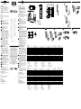
Starting operation
1 Mode L = light-switching: When light is received, output Q is active
(e. g. only substrate).
Mode D = dark-switching: When the light beam is interrupted,
output Q is active (e. g. label and substrate) = factory setting.
2 Connect and secure cable receptacle tension-free. The following apply
for connection in B: brn = brown, blu = blue, blk = black, wht = white.
Connect cables.
3 Mount sensor to suitable holders and align it roughly.
Move the material to be scanned in a taut state and utter-free
through the fork opening.
Connect sensor to operating voltage (see type label).
4a Dynamic teach-in (recommended)
Start teach-in: Press “+” and “–” pushbuttons simultaneously for
> 1 s and then let go. Yellow LED blinks at about 8 Hz. Move several
labels with substrate (objects to be detected) through the sensor.
Quit teach-in: Press “–” pushbutton. The switching threshold is set.
Function indicator (yellow LED) goes out. If the yellow function indicator
ashes 3 times, the set threshold is in the lower tolerance range. Check
the function of the sensor. The function indicator (yellow LED) displays
the output state of the sensor. If necessary, the teach-in procedure
can be repeated, or the “+” / “-” pushbuttons can be used for ne
adjustment.
4b Manual setting of the switching threshold / ne adjustment
(via “+” and “–” pushbuttons)
Single pressure = ne adjustment (yellow LED ashes per push
of button); holding the button pressed = quick adjustment
(yellow LED ashes until minimum or maximum is reached).
In Mode L = bright: The yellow function indicator illuminates when
the light received is at its optimum level. If it does not light up, too
little is being received: Increase sensitivity using the “+” pushbutton.
4c Static teach-in on substrate or label
The switching threshold can, if required, be taught in statically
(without material movement).
Start teach-in: Press “+” and “–” pushbuttons simultaneously for
> 1 s and then let go. Yellow LED blinks at about 8 Hz.
Quit teach-in: Press “–” pushbutton; switching threshold is set.
Function indicator (yellow LED) goes out. The yellow function indicator
ashes 3 times. The threshold is set in the lower tolerance range.
Check the function of the sensor. The function indicator (yellow LED)
displays the output state of the sensor. If necessary, the teach-in
procedure can be repeated, or the “+” / “–” pushbuttons can be used
for ne adjustment.
4d ET input external teach: for programming the switching threshold
via external signal. Yellow LED blinks at about 4 Hz. Can be used to
readjust the switching threshold via the control while the process
is running. Activation via IO-Link required.
4e Monitoring detection L = light-switching: Bring the substrate (gap
between labels) into the beam path. The function indicator (yellow)
must light up. Then bring the label and substrate into the beam path.
The function indicator (yellow) must go out. If it does not go out, reduce
the sensitivity with the “–” pushbutton until it goes out.
5 Press both the “+” and “–” pushbuttons together for 3 s to lock the
device to prevent unintentional actuation.
6 Press both the “+” and “–” pushbuttons together for 6 s to toggle
between light and dark switching.
7 IO-Link setting
The communication via IO-Link will be shown by the green LED.
Green LED blinks at about 1Hz.
Information on the IO-Link functions can be found in the enclosed
supplementary operating instructions for WFS IO-Link or downloaded
from www.sick.com under the device order number.
Switching threshold adaptation
Only, the rst teach-in procedure after switching on is permanently stored.
Teach-in can be repeated cyclically.
Note
Teach-in does not aect the sensor function; output Q switches.
A new switching threshold is set after the teach-in is quit.
Maintenance
SICK sensors are maintenance-free.
We recommend doing the following regularly:
- clean the external lens surfaces
- check the screw connections and plug-in connections.
No modications may be made to devices.
DEUTSCH
Gabelsensor
mit unsichtbarem Infrarotlicht
Betriebsanleitung
Sicherheitshinweise
> Vor der Inbetriebnahme die Betriebsanleitung lesen.
> Anschluss, Montage und Einstellung nur durch Fachpersonal.
> Kein Sicherheitsbauteil gemäß EU-Maschinenrichtlinie.
> UL: Nur zur Verwendung in Anwendungen gemäß NFPA 79.
Von UL gelistete Adapter mit Anschlusskabeln sind verfügbar.
Enclosure type 1.
> Gerät bei Inbetriebnahme vor Feuchte und Verunreinigung schützen.
> Diese Betriebsanleitung enthält Informationen, die während des
Lebenszyklus des Sensors notwendig sind.
Bestimmungsgemäße Verwendung
Der Gabel-Sensor WFS IO-Link ist ein optoelektronischer Sensor, der mit einer
Sende- und Empfangseinheit arbeitet. Er wird zum optischen, berührungs losen
Erfassen von Objekten, Etiketten und Marken eingesetzt.
Inbetriebnahme
1 Modus L = hellschaltend: Bei Lichtempfang ist der Ausgang Q aktiv
(z. B. nur Trägermaterial).
Modus D = dunkelschaltend: Bei Lichtunterbrechung ist der Ausgang
Q aktiv (z. B. Etikett und Trägermaterial) = Werkseinstellung.
2 Leitungsdose spannungsfrei aufstecken und festschrauben.
Für Anschluss in B gilt: brn = braun, blu = blau, blk = schwarz,
wht = weiß.
Leitungen anschließen.
3 Sensor mit Befestigungsbohrungen an geeignete Halter montieren und
grob ausrichten. Das Testmaterial im gespannten Zustand und atter-
frei durch die Gabelönung bewegen. Sensor an Betriebsspannung
legen (s. Typenaufdruck).
4a Dynamischer Teach-in (Empfohlen)
Start Teach-in: „+“- und „–“-Taste gleichzeitig für > 1 s drücken und
danach loslassen. Gelbe LED blinkt mit ca. 8 Hz. Mehrere Etiketten mit
Trägermaterial (zu detektierende Objekte) durch den Sensor bewegen.
Beenden Teach-in: „–“- Taste betätigen. Schaltschwelle wird gesetzt.
Funktionsanzeige (gelbe LED) erlischt. Blinkt die gelbe Funktionsan-
zeige 3-mal, ist die gesetzte Schwelle im unteren Toleranzbereich.
Über prüfen Sie die Funktion des Sensors. Die Funktionsanzeige (gelbe
LED) zeigt den Schaltzustand des Sensors an. Bei Bedarf kann der
Teach-in-Vorgang wiederholt oder „+“- / „–“-Tasten zur Feineinstellung
benutzt werden.
4b Manuelle Einstellung der Schaltschwelle / Feinjustage
(per „+“- und „–“-Tasten)
Einzeldruck = Feinjustage (gelbe LED blinkt pro Tastendruck);
Taste gedrückt halten = schnelle Verstellung (gelbe LED blinkt,
bis Minimum oder Maximum erreicht).
Im Modus L = hellschaltend: Bei optimalem Lichtempfang leuchtet
die gelbe Funktionsanzeige. Leuchtet sie nicht, wird zu wenig Licht
empfangen: Empndlichkeit mit „+“-Taste erhöhen.
4c Statischer Teach-in auf Trägermaterial oder Etikett
Die Schaltschwelle kann bei Bedarf auch statisch
(ohne Material bewegung) eingelernt werden.
Start Teach-in: „+“- und „–“-Taste gleichzeitig für > 1 s drücken und
danach loslassen. Gelbe LED blinkt mit ca. 8 Hz.
Beenden Teach-in: „–“-Taste bestätigen; Schaltschwelle wird gesetzt.
Funktionsanzeige (gelbe LED) erlischt. Die gelbe Funktionsanzeige
blinkt 3-mal. Die Schwelle wird im unteren Toleranzbereich gesetzt.
Überprüfen Sie die Funktion des Sensors. Die Funktionsanzeige
(gelbe LED) zeigt den Schaltzustand des Sensors an. Bei Bedarf kann
der Teach-in-Vorgang wiederholt oder die „+“- / „–“-Tasten zur Feinein-
stellung benutzt werden.
4d ET Eingang Extern Teach: zur Programmierung der Schaltschwelle
über externes Signal. Gelbe LED blinkt mit ca. 4 Hz. Kann genutzt
werden, um die Schaltschwelle über die Steuerung im laufenden
Prozess nachzuregeln. Aktivierung über IO-Link erforderlich.
4e Kontrolle Erfassung L = hellschaltend: Trägermaterial (Lücke
zwischen Etiketten) in Strahlengang bringen, die Funktionsanzeige
(gelb) muss leuchten. Anschließend Etikett und Trägermaterial in den
Strahlengang bringen, die Funktionsanzeige (gelb) muss erlöschen.
Erlischt sie nicht, die Empndlichkeit mit der „–“-Taste reduzieren,
bis sie erlischt.
5 Durch gleichzeitiges Drücken der „+“- und „–“-Tasten für 3 s kann
das Gerät gegen unbeabsichtigtes Betätigen verriegelt werden.
6 Durch gleichzeitiges Drücken der „+“- und „–“-Tasten für 6 s
kann zwischen Hell- und Dunkelschaltung umgeschaltet werden.
7 Einstellung IO-Link
Die Kommunikation über IO-Link wird von der grünen LED angezeigt.
Die grüne LED blinkt mit ca. 1 Hz.
Die IO-Link Funktionalitäten bitte der beiliegenden Zusatz-Betriebs-
anleitung WFS IO-Link entnehmen oder über www.sick.com unter der
Geräte-Bestellnummer downloaden.
Schaltschwellennachführung
Nur der erste Einlernvorgang nach dem Einschalten wird dauerhaft
gespeichert. Teach-in kann zyklisch wiederholt werden.
Hinweis
Teach-in beeinträchtigt die Sensorfunktion nicht; Ausgang Q schaltet. Neue
Schaltschwelle wird nach Beenden des Teach-in gesetzt.
Wartung
SICK-Sensoren sind wartungsfrei.
Wir empfehlen, in regelmäßigen Abständen
– die optischen Grenzächen zu reinigen
– Verschraubungen und Steckverbindungen zu überprüfen.
Veränderungen an Geräten dürfen nicht vorgenommen werden.
2
4c
More representatives and agencies at www.sick.com ∙ Subject to change
without notice ∙ The specied product features and technical data do not
represent any guarantee.
Weitere Niederlassungen nden Sie unter www.sick.com ∙ Irrtümer
und Änderungen vorbehalten ∙ Angegebene Produkteigenschaften und
technische Daten stellen keine Garantieerklärung dar.
Plus de représentations et d’agences à l’adresse www.sick.com ∙ Sujet à
modication sans préavis ∙ Les caractéristiques de produit et techniques
indiquées ne constituent pas de déclaration de garantie.
Para mais representantes e agências, consulte www.sick.com ∙ Alterações
poderão ser feitas sem prévio aviso ∙ As características do produto e os
dados técnicos apresentados não constituem declaração de garantia.
Altri rappresentanti ed agenzie si trovano su www.sick.com ∙ Contenuti
soggetti a modiche senza preavviso ∙ Le caratteristiche del prodotto e i dati
tecnici non rappresentano una dichiarazione di garanzia.
Más representantes y agencias en www.sick.com ∙ Sujeto a cambio sin
previo aviso ∙ Las características y los datos técnicos especicados no
constituyen ninguna declaración de garantía.
欲了解更多代表机构和代理商信息,请登录 www.sick.com ∙
如有更改 , 不另行通知 ∙ 对所给出的产品特性和技术参数
的正确性不予保证。
その他の営業所は www.sick.com よりご覧ください ∙ 予告なしに変更される
ことがあります ∙ 記載されている製品機能および技術データは保証を明示す
るものではありません。
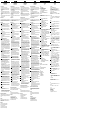
WFS IO-Link xxPxxx xxNxxx
Fork width Gabelweite Passage Distancia de detecção 3 mm 3 mm
Supply voltage V
S
Versorgungsspannung U
V
Tension d'alimentation U
V
Tensão de força U
V
10 ... 30 V DC
1)
10 ... 30 V DC
1)
Output current I
max.
Ausgangsstrom I
max.
Courant de sortie I
max.
Corrente de saída I
max.
100 mA
2)
100 mA
2)
Switching output Schaltausgang Sortie de commutation Saída de conexão PNP NPN
Initialisation time Initialisierungszeit Temps d’initialisation Tempo de inicialização 40 ms 40 ms
Response time Ansprechzeit Temps de réponse Tempo de reação 35 µs
3)
35 µs
3)
Switching frequency Schaltfrequenz Fréquence de commutation Frequência de comutação 15 kHz
5)
15 kHz
5)
Jitter Jitter Scintillement Jitter 15 µs 15 µs
Teach-in input (ET) Eingang Teach-in (ET) Entrée apprentissage (ET) Entrada Teach-in (ET) Teach: U > 5 V ...< U
V
RUN: U < 4 V
Teach: U < (U
V
- 6 V)
RUN: U > (U
V
- 5 V)
Smallest detectable object Kleinstes detektierbares Objekt Plus petit objet détectable O mais pequeno objecto detectado 2 mm (0.08 in.)
4)
2 mm (0.08 in.)
4)
Enclosure rating Schutzart Type de protection Tipo de proteção IP 65 IP 65
Protection class Schutzklasse Classe de protection Classe de proteção
Circuit protection Schutzschaltungen Circuits de protection Circuitos protetores A, B, C
6)
A, B, C
6)
Ambient operating temperature Betriebsumgebungstemperatur Température ambiante Temperatura ambiente de operação –20 … + 60 °C –20 … + 60 °C
1)
Limit value:
operation in short-circuit protection mains max. 8 A;
residual ripple max. 5 Vss
2)
Minimum output current 0.3 mA
3)
With light / dark ratio 1:1
4)
Gap between labels
5)
during teach 6 kHz
6)
A = V
S
connections reverse polarity protected
B = Outputs protected against short circuits
C = Interference pulse suppression
1)
Grenzwerte:
Betrieb im kurzschlussgeschützten
Netz max. 8 A; Restwelligkeit max. 5 Vss
2)
Minimaler Ausgangsstrom 0,3 mA
3)
Bei Hell-Dunkelverhältnis 1:1
4)
Spalt zwischen Etiketten
5)
während Teach 6 kHz
6)
A = U
V
-Anschlüsse verpolsicher
B = Ausgänge kurzschlussfest
C = Störimpulsunterdrückung
1)
Valeurs limites :
fonctionnement sur réseau protégé contre les
courts-circuits max. 8 A ; ondulation résiduelle max. 5 Vcc
2)
Courant de sortie minimal 0,3 mA
3)
Pour un rapport clair / sombre de 1 : 1
4)
Interstice entre étiquettes
5)
pendant l’apprentissage 6 kHz
6)
A = Raccordements U
v
protégés contre les inversions de polarité
B = Sorties protégées contre les courts-circuits
C = Suppression des impulsions parasites
1)
Valores limite:
funcionamento com rede à prova de curto-circuito máx. 8 A;
ondulação residual máx. 5 Vss
2)
Corrente mínima de saída 0,3 mA
3)
No caso de uma relção claro-escuro de 1:1
4)
Fenda entre etiquetas
5)
durante o Teach 6kHz
6)
A = Conexões U
V
protegidas contra inversão de polos
B = Saídas protegidas contra curto circuito
C = Supressão de impulsos parasitas
WFS IO-Link xxPxxx xxNxxx
Invaco Distancia de detección
叉 形 宽 度
フォーク幅
3 mm 3 mm
Tensione di alimentazione U
V
Tension d'alimentation U
V
电 源 电 压 U
V
供給電圧 U
V
10 ... 30 V DC
1)
10 ... 30 V DC
1)
Corrente di uscita max. I
max.
Corriente de salida I
max.
输 出 电 流 I
max.
最大出力電流 I
max.
100 mA
2)
100 mA
2)
Uscita di commutazione Salida de conmutación
开 关 输 出
スイッチング出力
PNP NPN
Tempo di inizializzazione Tiempo de inicialización
初 始 启 动 时 间
初期化時間
40 ms 40 ms
Tempo di risposta Tiempo de reacción
触 发 时 间
応答時間
35 µs
3)
35 µs
3)
Frequenza di commutazione Frecuencia de conmutación
开关频率
スイッチング頻度
15 kHz
5)
15 kHz
5)
Jitter Inestabilidad
抖动
ステップ偏差
(Jitter) 15 µs 15 µs
Ingresso Teach-in (ET) Entrada Teach-in (ET)
示教输入(ET)
ティーチイン入力 (ET)
Teach: U > 5 V ...< U
V
RUN: U < 4 V
Teach: U < (U
V
- 6 V)
RUN: U > (U
V
- 5 V)
Oggetto minimo rilevabile Objeto mínimo detectable
可 被 感 知 的 最 小 的 物 件
小型の検出可能な対象物
2 mm (0.08 in.)
4)
2 mm (0.08 in.)
4)
Tipo di protezione Tipo de protección
保 护 种 类 保護等級
IP 65 IP 65
Classe di protezione Protección clase
保 护 级 别 保護クラス
Commutazioni di protezione Circuitos de protección
保 护 电 路
保護回路
A, B, C
6)
A, B, C
6)
Temperatura ambiente circostante Temperatura ambiente de servicio
工 作 环 境 - 温 度 使用周囲温度
–20 … + 60 °C –20 … + 60 °C
1)
Valori limite:
funzionamento in rete protetta da cortocircuito max. 8 A;
ondulazione
residua max. 5 Vss
2)
Corrente d'uscita minimale 0,3 mA
3)
Con un rapporto chiaro-scuro 1:1
4)
Fessura tra etichette
5)
durante il teach 6 kHz
6)
A = U
V
-collegamenti con protez. contro inversione di poli
B = Uscite a prova di corto circuito
C = Soppressione impulsi di disturbo
1)
Valores límite:
funcionamiento en red protegida contra cortocircuitos máx. 8 A; ondula-
ción residual máx. 5 Vss
2)
Corriente mínima de salida 0,3 mA
3)
En caso de relación claro - oscuro
4)
Ranura entre etiquetas de 1:1
5)
durante el teach 6 kHz
6)
A = Conexiones U
V
a prueba de inversión de polaridad
B = Salidas resistentes al cortocircuito
C = Represión de impulso de interferencia
1)
极限值:
在防短路电网中运行,最大 8 A;
最大余波 5 Vss
2)
最 小 输 出 电 流 0,3 mA
3)
暗 - 亮 比 为 1:1
4)
标 签(或 长 度)
5)
教学期间为 6 kHz
6)
A = U
V
-接 头 防 反 接
B = 输 出 端 抗 过 流 - 及 短 路
C = 消 除 干 扰 脉 冲
1)
限界値:
短絡保護の操作は最大 8 A;
残留リップルは最大 5 Vss
2)
最小出力電流 0.3 mA
3)
明暗比率 1:1の場合
4)
ラベル間のスペース
5)
ティーチ中 (6 kHz)
6)
A = U
V
接続 逆接保護
B = 短絡防止出力
C = 干渉パルス抑制
42 (1.65)
Ø 4.2
(0.17)
7
(0.28)
3 (0.12)
10
(0.39)
43 (1.69)
10
(0.39)
25
(0.98)
19
(0.75)
11
(0.43)
3
(0.12)
3
(0.12)
5
(0.2)
8
(0.31)
2.8
(0.11)
57.3 (2.26)
All dimensions in mm (inch)
1
(0.04)
5.3 (0.21)
11
44
3333
22
L+ M
Q Q
brnbrn
blkblk
blublu
whtwht
ML+
NC NC
Q
PNP
Q
NPN
Q
NPN
Q
PNP
1
3
42
PNP/NPN
L
D
4b / 4e 5 6
1 Function Display: yellow LED /
Funktionsanzeige: gelbe LED
2 Indicator Power On: green LED /
Power On- Anzeige: grüne LED
3 “+” / “–” buttons and function button /
„+“- / „–“-Taste und Funktionstaste
1
L+
M
Q
PNP
/C
MF
3
4
2
brn
blu
blk
wht
1
L+
M
Q
NPN
/C
MF
3
4
2
brn
blu
blk
wht
+
–
+
–
3 s
+
–
+
–
3 s
+
–
+
–
6 s
LD
3s
6s
1s TI
1s TII
4a
A
B
Seite wird geladen ...
-
 1
1
-
 2
2


SICK WFS IO-Link Bedienungsanleitung
- Kategorie
- Spielzeuge
- Typ
- Bedienungsanleitung
in anderen Sprachen
- English: SICK WFS IO-Link Operating instructions
- français: SICK WFS IO-Link Mode d'emploi
- español: SICK WFS IO-Link Instrucciones de operación
- italiano: SICK WFS IO-Link Istruzioni per l'uso
- português: SICK WFS IO-Link Instruções de operação
- 日本語: SICK WFS IO-Link 取扱説明書
Verwandte Artikel
-
SICK SENSICK WFS Bedienungsanleitung
-
-
-
-
-
-
-
-
-