
Dell™ PowerEdge™
2900 Systems
Information Update

Notes, Notices, and Cautions
NOTE: A NOTE indicates important information that helps you make better use
of your computer.
NOTICE: A NOTICE indicates either potential damage to hardware or loss of data
and tells you how to avoid the problem.
CAUTION: A CAUTION indicates a potential for property damage, personal injury,
or death.
____________________
Information in this document is subject to change without notice.
© 2006–2009 Dell Inc. All rights reserved.
Reproduction of these materials in any manner whatsoever without the written permission of Dell Inc.
is strictly forbidden.
Trademarks used in this text: Dell, the DELL logo, and PowerEdge are trademarks of Dell Inc.; Intel
and Xeon are registered trademarks of Intel Corporation; Microsoft, Windows, and Windows Server
are either trademarks or registered trademarks of Microsoft Corporation in the United States and/or
other countries; Red Hat and Red Hat Enterprise Linux are registered trademarks of Red Hat, Inc.;
SUSE is a registered trademark of Novell Inc.
Other trademarks and trade names may be used in this document to refer to either the entities claiming
the marks and names or their products. Dell Inc. disclaims any proprietary interest in trademarks and
trade names other than its own.
May 2009 P/N YC469 Rev. A06

Contents 3
Contents
PowerEdge 2900 III – New System Features . . . . . . . 5
New Performance Features
. . . . . . . . . . . . . 5
New I/O and Storage Features
. . . . . . . . . . . . 5
New Security Features
. . . . . . . . . . . . . . . . 5
Optional Internal USB Memory Key
. . . . . . . . . . . . 6
Installing the Optional Internal USB
Memory Key
. . . . . . . . . . . . . . . . . . . . . 7
Processor Upgrades – PowerEdge 2900 II
and PowerEdge 2900 III Systems
. . . . . . . . . . . . . 9
System Board Replacement – Safeguarding
Encrypted Data
. . . . . . . . . . . . . . . . . . . . . . . 9
System Message Update
. . . . . . . . . . . . . . . . . 10
LCD Status Messages Update
. . . . . . . . . . . . . . 14
System Setup Program Update
. . . . . . . . . . . . . 19
Memory Screen
. . . . . . . . . . . . . . . . . . . 19
CPU Information Screen
. . . . . . . . . . . . . . 20
Integrated Devices Screen
. . . . . . . . . . . . . 20
System Security Screen
. . . . . . . . . . . . . . 21
Serial Communication Screen
. . . . . . . . . . . 22

4 Contents
Operating System Information . . . . . . . . . . . . . . 22
Enumeration of NICs
. . . . . . . . . . . . . . . . 22
SATA Optical Drive Support on RHEL3
and SLES9
. . . . . . . . . . . . . . . . . . . . . . 23
RHEL – Incorrect Processor Information
. . . . . . 23
System Support for Microsoft Windows 2000
. . . 23
Hardware Owner’s Manual Updates
. . . . . . . . . . 24
Installing the Processor
. . . . . . . . . . . . . . . 24
System Diagnostics Custom Test Options
. . . . . 24
System Board Replacement Update
(Service-Only Procedure)
. . . . . . . . . . . . . . . . 24

Information Update 5
This document provides updated information for your system
on the following topics:
• New system features for
PowerEdge™ 2900 III systems
• Internal USB memory key for
PowerEdge 2900 III systems
• Processor upgrades for
PowerEdge 2900 II and PowerEdge 2900 III
systems
• System board replacement – safeguarding encrypted data
• System message update for
PowerEdge
2900 III system
• LCD status message update for
PowerEdge
2900 III systems
• System Setup program update for
PowerEdge
2900 III systems
• Operating system information
•
Hardware Owner’s Manual
updates
• System board replacement (service-only procedure)
PowerEdge 2900 III – New System Features
New Performance Features
• Two dual-core or quad-core Intel
®
Xeon
®
processors.
New I/O and Storage Features
• Optional Intel quad-port Gigabit Ethernet NIC, capable of supporting
10-Mbps, 100-Mbps, and 1000-Mbps data rates, and iSCSI remote boot.
• Support for 10 Gb Ethernet cards.
• One internal USB 2.0-compliant connector supporting an optional
bootable USB flash drive or USB memory key.
• Support for optional SAS 6i/R and PERC 6/i adapters.
New Security Features
• Trusted Program Module (TPM) support for improved security.
• Optional support for iSCSI boot.

6 Information Update
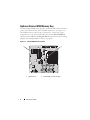
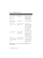
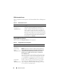
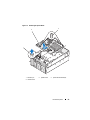
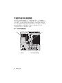
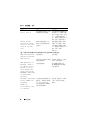
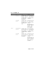
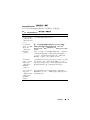
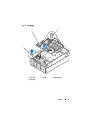
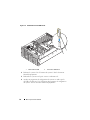
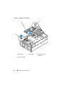
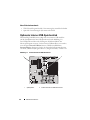
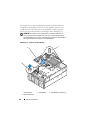
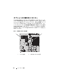
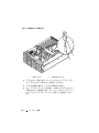
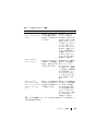
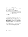
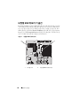
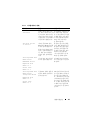
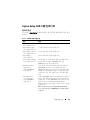
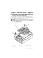
Optional Internal USB Memory Key
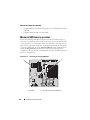
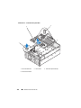
The PowerEdge 2900 III system provides an internal USB connector located
on the system board for use with a USB flash memory key (see Figure 1-1).
The USB memory key can be used as a boot device, security key, or mass
storage device. To use the internal USB connector, the Internal USB Port
option must be enabled in the Integrated Devices screen of the System Setup
program. See "Integrated Devices Screen" on page 20.
Figure 1-1. Internal USB Connector Location
1 system board 2 internal USB connector location
1 2

Information Update 7
To boot from the USB memory key, you must configure the USB memory
key with a boot image and then specify the USB memory key in the boot
sequence in the System Setup program. See “
Using the System Setup
Program” in the
Hardware Owner’s Manual
. For information on creating
a bootable file on the USB memory key, see the user documentation that
accompanied the USB memory key.
NOTE: USB keys that contain multiple LUNs (Logical Unit Numbers) must
be formatted using the format utility provided by the key manufacturer.
NOTICE: To avoid interference with components inside the system, the USB key
must conform to the following maximum dimensions: 12.7mm thick (0.5”) x 30.48mm
width (1.2”) x 71.12mm length (2.8”).
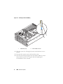
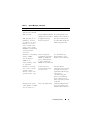
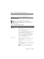
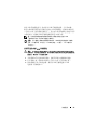
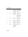
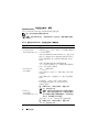
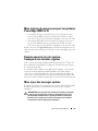
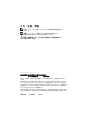
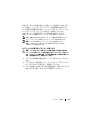
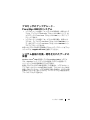
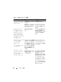
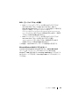
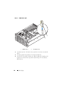
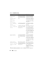
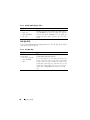
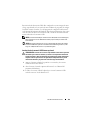
Installing the Optional Internal USB Memory Key
CAUTION: Only trained service technicians are authorized to remove the system
cover and access any of the components inside the system. See your Product
Information Guide for complete information about safety precautions, working
inside the computer, and protecting against electrostatic discharge.
1
Turn off the system, including any attached peripherals, and disconnect
the system from its electrical outlet.
2
Open the system. See “Opening the System” in the
Hardware Owner’s
Manual
.
3
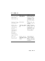
Locate the USB connector on the system board, and insert the USB
memory key into the USB connector. See Figure 1-2.

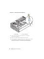
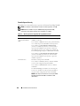
8 Information Update
Figure 1-2. Installing an Internal USB Key
4
Close the system. See “Closing the System” in the
Hardware Owner’s
Manual
.
5
Reconnect the system to power and restart the system.
6
Enter the System Setup program and verify that the USB key has been
detected by the system. See “Using the System Setup Program”
in the
Hardware Owner’s Manual
.
1 USB memory key 2 internal USB connector
9
8
1
2

Information Update 9
Processor Upgrades – PowerEdge 2900 II
and PowerEdge 2900 III Systems
• If the front of your system chassis is labeled with a “II”, your system is
upgradeable to the 5100 series of dual-core Intel Xeon processors and
the 5300 series of quad-core Intel Xeon processors.
• If the front of your system chassis is labeled with a “III”, your system is
upgradeable to the 5100 and 5200 series of dual-core Intel Xeon processors
and the 5300 and 5400 series of quad-core Intel Xeon processors.
See support.dell.com for information on the latest processor upgrade options
for your system.
System Board Replacement –
Safeguarding Encrypted Data
On PowerEdge 2900 III systems using Windows Server
®
2008, you can use
encryption programs, such as the BitLocker utility, to secure the contents
of the hard drive.
If you are using the TPM with an encryption program, you are prompted to
create a recovery key during system setup. Be sure to store this recovery key.
If you replace the system board, you must supply the recovery key when you
restart your system before you can access the encrypted files on your hard
drive(s).

10 Information Update
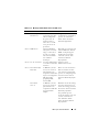
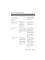
System Message Update
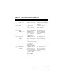
Table 1-1 lists new system messages for the PowerEdge 2900 III system
and the probable cause and corrective action if the message appears.
CAUTION: Only trained service technicians are authorized to remove the system
cover and access any of the components inside the system. See your Product
Information Guide for complete information about safety precautions,
working inside the computer, and protecting against electrostatic discharge
Table 1-1. System Messages
Message Causes Corrective Actions
Alert! Node
Interleaving
disabled! Memory
configuration does
not support Node
Interleaving.
The memory configuration
does not support node
interleaving, or the
configuration has changed
(for example, a failed
DIMM) so that node
interleaving cannot be
supported.
The system
runs but with reduced
functionality.
Ensure that the memory
modules are installed in a
configuration that supports
node interleaving. Check
other system messages
for additional information
for possible causes.
For memory configuration
information, see
“General Memory Module
Installation Guidelines”
in the Hardware Owner’s
Manual. If the problem
persists, see
“Troubleshooting System
Memory” in the Hardware
Owner’s Manual.
!!*** Error: Remote
Access Controller
initialization
failure *** RAC
virtual USB devices
may not be
available...
Remote Access Controller
initialization failure
Ensure that the Remote
Access Controller is
properly installed. See
“Installing a RAC Card”
in the Hardware Owner’s
Manual.
Invalid PCIe
card found in the
Internal_Storage
slot!
The system halted because
an invalid PCIe expansion
card is installed in the
dedicated storage controller
slot.
Remove the PCIe expansion
card and install the internal
SAS controller in the
dedicated slot.

Information Update 11
No boot device
available
Faulty or missing optical
drive subsystem, hard drive,
or hard-drive subsystem, or
no bootable USB key
installed.
Use a bootable USB key,
CD, or hard drive. See
“Using the System Setup
Program” in the Hardware
Owner’s Manual for
information on setting
the order of boot devices.
PCI BIOS failed
to install
PCIe device BIOS (Option
ROM) checksum failure
detected during shadowing.
Cables to expansion card(s)
loose; faulty or improperly
installed expansion card(s).
Reseat the expansion
card(s). Ensure that all
appropriate cables are
securely connected to the
expansion card(s). If the
problem persists, see
“Troubleshooting System
Expansion Cards” in the
Hardware Owner’s Manual.
PCIe Degraded
Link Width Error:
Embedded device
Expected Link
Width is n
Actual Link
Width is n
Faulty system board
or riser board.
See “Getting Help” in the
Hardware Owner’s Manual.
PCIe Degraded
Link Width Error:
Integrated device
Expected Link
Width is n
Actual Link
Width is n
The specified PCIe device is
faulty or improperly
installed.
For a SAS controller
daughter card, reseat the
card in the dedicated PCIe
connector. See “Installing
a SAS Controller Daughter
Card” in the Hardware
Owner’s Manual. If the
problem persists, see
“Getting Help” in the
Hardware Owner’s Manual.
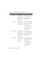
Table 1-1. System Messages (continued)
Message Causes Corrective Actions

12 Information Update
PCIe Degraded Link
Width Error: Slot n
Expected Link
Width is n
Actual Link
Width is n
Faulty or improperly
installed PCIe card in
the specified slot.
Reseat the PCIe card in the
specified slot number. See
“Expansion Cards” in the
Hardware Owner’s Manual.
If the problem persists,
see “Getting Help” in the
Hardware Owner’s Manual.
PCIe Training
Error: Embedded
device
Faulty system board
or riser board.
See “Getting Help” in the
Hardware Owner’s Manual.
PCIe Training
Error: Integrated
device
The specified PCIe device
is faulty or improperly
installed.
For a SAS controller
daughter card, reseat the
card in the dedicated PCIe
connector. See “Installing a
SAS Controller Daughter
Card” in the Hardware
Owner’s Manual. If the
problem persists, see
“Getting Help” in the
Hardware Owner’s Manual.
PCIe Training
Error: Slot n
Faulty or improperly
installed PCIe card
in the specified slot.
Reseat the PCIe card in the
specified slot number. See
“Expansion Cards” in the
Hardware Owner’s Manual.
If the problem persists,
see “Getting Help” in the
Hardware Owner’s Manual.
Remote Access
Controller cable
error or incorrect
card in the RAC
slot.
RAC cables not connected,
or RAC card installed in
wrong expansion slot.
Check that the RAC cables
are connected, and that the
RAC card is installed in the
correct expansion slot.
See “Installing a RAC Card”
in the Hardware Owner’s
Manual.
NOTE: All TPM information messages appear after the BMC option ROM has been
loaded during POST.
Table 1-1. System Messages (continued)
Message Causes Corrective Actions

Information Update 13
TPM configuration
operation honored.
System now resets. Information only.
TPM Failure
A Trusted Platform Module
(TPM) function has failed.
See “Getting Help” in the
Hardware Owner’s Manual.
TPM operation is
pending. Press I
to Ignore or M to
Modify to allow
this change and
reset the system.
WARNING: Modifying
could prevent
security.
Configuration change
has been requested.
Press I to continue system
boot. Press M to modify the
TPM setting and restart.
Warning: Following
faulty DIMMs
are disabled:
DIMM n
1
n
2
Total memory size
is reduced.
Faulty or improperly
seated memory module(s).
DIMMs are disabled in
pairs, as indicated by the
n
1
and n
2
. Check both
DIMMs for a possible fault.
See “Troubleshooting
System Memory” in the
Hardware Owner’s Manual.
Warning: A fatal
error has caused
system reset!
Please check the
system event log!
A fatal system error
occurred and caused the
system to restart.
Check the SEL for
information that was logged
during the error. See the
applicable troubleshooting
section in See
“Troubleshooting Your
System” in the Hardware
Owner’s Manual. for any
faulty components specified
in the SEL.
Warning! No micro
code update loaded
for processor n
Micro code update failed. Update the BIOS firmware.
See “Getting Help” in the
Hardware Owner’s Manual.
Table 1-1. System Messages (continued)
Message Causes Corrective Actions

14 Information Update
LCD Status Messages Update
Table 1-2 lists updates to the LCD status messages that can occur on
the PowerEdge 2900 III system and the probable cause for each message.
The LCD messages refer to events recorded in the system event log (SEL).
For information on the SEL and configuring system management settings,
see your systems management software documentation.
Warning: The
installed memory
configuration is
not optimal. For
more information
on valid memory
configurations,
please see
the system
documentation
on the technical
support web site.
Invalid memory
configuration. The system
runs but with reduced
functionality.
Ensure that the memory
modules are installed in
a valid configuration. See
“General Memory Module
Installation Guidelines”
in the Hardware Owner’s
Manual. If the problem
persists, see
“Troubleshooting System
Memory” in the Hardware
Owner’s Manual.
Write fault
Write fault on
selected drive
Faulty USB device, USB
medium, optical drive
assembly, hard drive, or
hard-drive subsystem.
Replace the faulty media.
Reseat the USB device or
USB cable. For hard drive
problems, see
“Troubleshooting a Hard
Drive” in the Hardware
Owner’s Manual.
Table 1-1. System Messages (continued)
Message Causes Corrective Actions

Information Update 15
Table 1-2. LCD Status Messages
Code Text Causes Corrective Actions
N/A SYSTEM NAME
A 62-character string that
can be defined by the user
in the System Setup
program.
The SYSTEM NAME
displays under the
following conditions:
• The system
is powered on.
• The power is off
and active errors
are displayed.
This message is for
information only.
You can change the
system ID and name
in the System Setup
program. See “Using the
System Setup Program”
in the Hardware Owner’s
Manual.
E1000 FAILSAFE,
Call Support
Check the system event
log for critical failure
events.
See “Getting Help” in
the Hardware Owner’s
Manual.
E1118 CPU Temp
Interface
The BMC is unable to
determine the CPU(s)
temperature status.
Consequently, the BMC
increases the CPU fan
speed to maximum
as a precautionary
measure.
Turn off power to the
system and restart the
system. If the problem
persists, see “Getting
Help” in the Hardware
Owner’s Manual.
E1211 ROMB Batt
RAID battery is either
missing, bad, or unable to
recharge due to thermal
issues.
Reseat the RAID battery
connector. See the “RAID
Battery” and see
“Troubleshooting System
Cooling Problems” in
the Hardware Owner’s
Manual.
E1625 PS AC Current
Power source is out
of acceptable range.
Check the AC power
source.

16 Information Update
E1711 PCI PERR B##
D## F##
The system BIOS has
reported a PCI parity error
on a component that
resides in PCI
configuration space
at bus ##, device ##,
function ##.
Remove and reseat the
PCIe expansion cards.
If the problem persists,
see “Troubleshooting
an Expansion Card”
in the Hardware Owner’s
Manual.
PCI PERR
Slot #
The system BIOS has
reported a PCI parity error
on a component that
resides in the specified
PCIe slot.
Reinstall the expansion-
card riser. See “Expansion
Card Risers” in the
Hardware Owner’s
Manual.
If the problem persists,
the riser card or system
board is faulty. See
“Getting Help”
in the Hardware Owner’s
Manual.
E1712 PCI SERR B##
D## F##
The system BIOS has
reported a PCI system
error on a component that
resides in PCI
configuration space at bus
##, device ##, function
##.
Remove and reseat the
PCIe expansion cards.
If the problem persists,
see “Troubleshooting
Expansion Cards” in
the Hardware Owner’s
Manual.
PCI SERR
Slot #
The system BIOS has
reported a PCI system
error on a component
that resides in the
specified slot.
Reinstall the expansion-
card riser. See “Expansion
Card Risers” in the
Hardware Owner’s
Manual.
If the problem persists,
the riser card or system
board is faulty. See
“Getting Help” in
the Hardware Owner’s
Manual.
Table 1-2. LCD Status Messages (continued)
Code Text Causes Corrective Actions

Information Update 17
E171F PCIE Fatal Err
B## D## F##
The system BIOS has
reported a PCIe fatal error
on a component that
resides in PCIe
configuration space at bus
##, device ##, function
##.
Remove and reseat the
PCIe expansion cards.
If the problem persists,
see “Troubleshooting
Expansion Cards” in
the Hardware Owner’s
Manual.
PCIE Fatal Err
Slot #
The system BIOS has
reported a PCIe fatal error
on a component that
resides in the specified
slot.
Reinstall the expansion-
card riser. See “Expansion
Card Risers” in the
Hardware Owner’s
Manual.
If the problem persists,
the riser card or system
board is faulty. See
“Getting Help” in the
Hardware Owner’s
Manual.
E1914 DRAC5 Conn2
Cbl
DRAC 5 cable is missing
or disconnected.
Reconnect the cable. See
“Installing a RAC Card”
in the Hardware Owner’s
Manual.
E1B01 USB#
Overcurrent
Device plugged in the
specified USB port caused
an overcurrent condition.
Reseat the device cable.
If the problem persists,
replace or remove the
device.
E2110 MBE DIMM # & #
One of the two indicated
DIMMs has had a memory
multi-bit error (MBE).
See “Troubleshooting
System Memory” in
the Hardware Owner’s
Manual.
Table 1-2. LCD Status Messages (continued)
Code Text Causes Corrective Actions

18 Information Update
NOTE: Each diagnostic LCD message is assigned a priority. The highest priority
messages supersede any group of messages with a lower priority.
E2111 SBE Log
Disable DIMM #
The system BIOS has
disabled memory single-
bit error (SBE) logging,
and does not resume
logging further SBEs until
the system is restarted.
“#” represents the DIMM
implicated by the BIOS.
See “Troubleshooting
System Memory”
in the Hardware Owner’s
Manual.
E2112 Mem Spare
DIMM #
The system BIOS has
spared the memory
because it has determined
that the memory had too
many errors. “# & #”
represents the DIMM pair
implicated by the BIOS.
See “Troubleshooting
System Memory”
in the Hardware Owner’s
Manual.
I1915 Video Off
(LCD lights with
a blue or amber
background.)
The video is turned off by
the RAC remote user.
Information only.
I1916 Video Off
in ##
(LCD lights with
a blue or amber
background.)
The video is turned off in
xx seconds by the RAC
remote user.
Information only.
Table 1-2. LCD Status Messages (continued)
Code Text Causes Corrective Actions

Information Update 19
System Setup Program Update
Memory Screen
Table 1-3 lists the descriptions for the information fields that appear
on the Memory Information screen.
Table 1-3. Memory Information Screen Options
Option Description
System Memory Size Displays the amount of system memory.
System Memory Type Displays the type of system memory.
System Memory Speed Displays the system memory speed.
Video Memory Displays the amount of video memory.
System Memory Testing Specifies whether system memory tests are run at system
boot. Options are Enabled and Disabled.
Redundant Memory
(Disabled default)
Enables or disables the redundant memory feature.
When set to Spare Mode, the first rank of memory on
each DIMM is reserved for memory sparing. Redundant
memory feature is disabled if the Node Interleaving field
is enabled.
Node Interleaving
(Disabled default)
If this field is set to Enabled, memory interleaving is
supported if a symmetric memory configuration is
installed. If this field is set to Disabled, the system can
support Non-Uniform Memory architecture (NUMA)
(asymmetric) memory configurations.
NOTE: The Node Interleaving field must be set to Disabled
when using the redundant memory feature.
Low Power Mode
(Disabled default)
Enables or disables the low power mode of the memory.
When set to Disabled, the memory runs at full speed.
When set to Enabled, the memory runs at a reduced
speed to conserve energy.

20 Information Update
CPU Information Screen
Table 1-4 updates the description for the Demand-Based Power Management
option.
Integrated Devices Screen
Table 1-5 lists new Integrated Devices screen options.
Table 1-4. CPU Information Screen
Option Description
Demand-Based Power
Management
(Enabled default)
NOTE: Check your operating system documentation to
verify if the operating system supports this feature.
Enables or disables demand-based power management.
When enabled, the CPU Performance State tables are
reported to the operating system; when disabled, the CPU
Performance State tables are not reported to the operating
system. If any of the CPUs do not support demand-based
power management, the field becomes read-only, and is
automatically set to Disabled.
Table 1-5. Integrated Devices Screen Options
Option Description
Internal USB Port
(On default)
Enables or disables the system’s internal USB port.
OS Watchdog
Timer
(Disabled default)
NOTE: This feature is usable only with operating systems that
support WDAT implementations of the Advanced Configuration
and Power Interface (ACPI) 3.0b specification. Microsoft
®
Windows Server
®
2008 supports this feature, but Windows
Server 2003 does not.
Sets a timer that monitors the operating system for activity and
aids in recovery if the system stops responding. When this field
is set to Enabled, the operating system is allowed to initialize
the timer. When set to Disabled, the timer is not initialized.
I/OAT DMA
Engine
(Disabled default)
Enables or disables the I/O Acceleration Technology (I/OAT)
option. When set to Enabled, I/OAT reduces system CPU
usage for applications that use TCP by offloading part of TCP
receive operation to the DMA engine.
Seite laden ...
Seite laden ...
Seite laden ...
Seite laden ...
Seite laden ...
Seite laden ...
Seite laden ...
Seite laden ...
Seite laden ...
Seite laden ...
Seite laden ...
Seite laden ...
Seite laden ...
Seite laden ...
Seite laden ...
Seite laden ...
Seite laden ...
Seite laden ...
Seite laden ...
Seite laden ...
Seite laden ...
Seite laden ...
Seite laden ...
Seite laden ...
Seite laden ...
Seite laden ...
Seite laden ...
Seite laden ...
Seite laden ...
Seite laden ...
Seite laden ...
Seite laden ...
Seite laden ...
Seite laden ...
Seite laden ...
Seite laden ...
Seite laden ...
Seite laden ...
Seite laden ...
Seite laden ...
Seite laden ...
Seite laden ...
Seite laden ...
Seite laden ...
Seite laden ...
Seite laden ...
Seite laden ...
Seite laden ...
Seite laden ...
Seite laden ...
Seite laden ...
Seite laden ...
Seite laden ...
Seite laden ...
Seite laden ...
Seite laden ...
Seite laden ...
Seite laden ...
Seite laden ...
Seite laden ...
Seite laden ...
Seite laden ...
Seite laden ...
Seite laden ...
Seite laden ...
Seite laden ...
Seite laden ...
Seite laden ...
Seite laden ...
Seite laden ...
Seite laden ...
Seite laden ...
Seite laden ...
Seite laden ...
Seite laden ...
Seite laden ...
Seite laden ...
Seite laden ...
Seite laden ...
Seite laden ...
Seite laden ...
Seite laden ...
Seite laden ...
Seite laden ...
Seite laden ...
Seite laden ...
Seite laden ...
Seite laden ...
Seite laden ...
Seite laden ...
Seite laden ...
Seite laden ...
Seite laden ...
Seite laden ...
Seite laden ...
Seite laden ...
Seite laden ...
Seite laden ...
Seite laden ...
Seite laden ...
Seite laden ...
Seite laden ...
Seite laden ...
Seite laden ...
Seite laden ...
Seite laden ...
Seite laden ...
Seite laden ...
Seite laden ...
Seite laden ...
Seite laden ...
Seite laden ...
Seite laden ...
Seite laden ...
Seite laden ...
Seite laden ...
Seite laden ...
Seite laden ...
Seite laden ...
Seite laden ...
Seite laden ...
Seite laden ...
Seite laden ...
Seite laden ...
Seite laden ...
Seite laden ...
Seite laden ...
Seite laden ...
Seite laden ...
Seite laden ...
Seite laden ...
Seite laden ...
Seite laden ...
Seite laden ...
Seite laden ...
Seite laden ...
Seite laden ...
Seite laden ...
Seite laden ...
Seite laden ...
Seite laden ...
Seite laden ...
Seite laden ...
Seite laden ...
Seite laden ...
Seite laden ...
Seite laden ...
Seite laden ...
Seite laden ...
Seite laden ...
Seite laden ...
Seite laden ...
Seite laden ...
Seite laden ...
Seite laden ...
Seite laden ...
Seite laden ...
Seite laden ...
Seite laden ...
Seite laden ...
Seite laden ...
Seite laden ...
Seite laden ...
Seite laden ...
Seite laden ...
Seite laden ...
Seite laden ...
Seite laden ...
Seite laden ...
Seite laden ...
-
 1
1
-
 2
2
-
 3
3
-
 4
4
-
 5
5
-
 6
6
-
 7
7
-
 8
8
-
 9
9
-
 10
10
-
 11
11
-
 12
12
-
 13
13
-
 14
14
-
 15
15
-
 16
16
-
 17
17
-
 18
18
-
 19
19
-
 20
20
-
 21
21
-
 22
22
-
 23
23
-
 24
24
-
 25
25
-
 26
26
-
 27
27
-
 28
28
-
 29
29
-
 30
30
-
 31
31
-
 32
32
-
 33
33
-
 34
34
-
 35
35
-
 36
36
-
 37
37
-
 38
38
-
 39
39
-
 40
40
-
 41
41
-
 42
42
-
 43
43
-
 44
44
-
 45
45
-
 46
46
-
 47
47
-
 48
48
-
 49
49
-
 50
50
-
 51
51
-
 52
52
-
 53
53
-
 54
54
-
 55
55
-
 56
56
-
 57
57
-
 58
58
-
 59
59
-
 60
60
-
 61
61
-
 62
62
-
 63
63
-
 64
64
-
 65
65
-
 66
66
-
 67
67
-
 68
68
-
 69
69
-
 70
70
-
 71
71
-
 72
72
-
 73
73
-
 74
74
-
 75
75
-
 76
76
-
 77
77
-
 78
78
-
 79
79
-
 80
80
-
 81
81
-
 82
82
-
 83
83
-
 84
84
-
 85
85
-
 86
86
-
 87
87
-
 88
88
-
 89
89
-
 90
90
-
 91
91
-
 92
92
-
 93
93
-
 94
94
-
 95
95
-
 96
96
-
 97
97
-
 98
98
-
 99
99
-
 100
100
-
 101
101
-
 102
102
-
 103
103
-
 104
104
-
 105
105
-
 106
106
-
 107
107
-
 108
108
-
 109
109
-
 110
110
-
 111
111
-
 112
112
-
 113
113
-
 114
114
-
 115
115
-
 116
116
-
 117
117
-
 118
118
-
 119
119
-
 120
120
-
 121
121
-
 122
122
-
 123
123
-
 124
124
-
 125
125
-
 126
126
-
 127
127
-
 128
128
-
 129
129
-
 130
130
-
 131
131
-
 132
132
-
 133
133
-
 134
134
-
 135
135
-
 136
136
-
 137
137
-
 138
138
-
 139
139
-
 140
140
-
 141
141
-
 142
142
-
 143
143
-
 144
144
-
 145
145
-
 146
146
-
 147
147
-
 148
148
-
 149
149
-
 150
150
-
 151
151
-
 152
152
-
 153
153
-
 154
154
-
 155
155
-
 156
156
-
 157
157
-
 158
158
-
 159
159
-
 160
160
-
 161
161
-
 162
162
-
 163
163
-
 164
164
-
 165
165
-
 166
166
-
 167
167
-
 168
168
-
 169
169
-
 170
170
-
 171
171
-
 172
172
-
 173
173
-
 174
174
-
 175
175
-
 176
176
-
 177
177
-
 178
178
-
 179
179
-
 180
180
-
 181
181
-
 182
182
-
 183
183
-
 184
184
-
 185
185
-
 186
186
-
 187
187
-
 188
188
-
 189
189
-
 190
190


in anderen Sprachen
- English: Dell PowerEdge 2900 User guide
- français: Dell PowerEdge 2900 Mode d'emploi
- español: Dell PowerEdge 2900 Guía del usuario
- 日本語: Dell PowerEdge 2900 ユーザーガイド
Verwandte Papiere
-
Dell PowerEdge 1950 Benutzerhandbuch
-
-
-
-
-
-
-
-
Dell PowerEdge 2950 Benutzerhandbuch
-
Dell PowerEdge T710 Benutzerhandbuch