Pepperl+Fuchs VBA-4E3A-KE-ZEJ/E2L-LEN Bedienungsanleitung
- Typ
- Bedienungsanleitung

Merkmale
www.pepperl-fuchs.com
Pepperl+Fuchs GmbH
68301 Mannheim · Germany
Te l . +49 621 776-4411
Fax +49 621 776-27-4411
E-mail: fa-info@de.pepperl-fuchs.com
Worldwide Headquarters
Pepperl+Fuchs GmbH · Mannheim · Germany
E-mail: fa-[email protected]
USA Headquarters
Pepperl+Fuchs Inc. · Tw i nsburg · USA
E-mail: fa-info@us.pepperl-fuchs.com
Asia Pacific Headquarters
Pepperl+Fuchs Pte Ltd · Singapore
E-mail: [email protected]
Company Registration No. 199003130E
AS-Interface-Sensor-/Aktuatormodul
AS-Interface sensor/actuator module
Part-No: 228784 EDM: 45-4764
Date: 2015-10-09 DIN A3 -> DIN A7
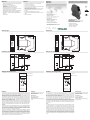
Abmessungen
Dimensions
Elektrischer Anschluss
Electrical connection
Adressen
Addresses
Features
Bestellbezeichnung
Model Number
VBA-4E3A-KE-ZEJ/E2L-LEN
KE-Schaltschrankmodul
4 Eingänge und 3 Ausgänge
KE switch cabinet module
4 inputs and 3 outputs
• Gehäuse mit abziehbaren und farbig codierten Klemmen
• Kommunikationsüberwachung
• Eingänge für 2- und 3-Draht-Sensoren
• Versorgung der Ausgänge aus der externen
Hilfsspannung
• Versorgung der Sensoren aus dem Modul
• Funktionsanzeige für Bus, externe Hilfsspannung, interne
Sensorversorgung, Ein- und Ausgänge
• Kanalbezogene rote LED-Anzeige bei Ausgangsüberlast
• Zuschaltbare Leitungsbrucherkennung (Ausgänge)
• A/B-Slave mit erweiterter Adressiermöglichkeit für bis zu
62 Slaves
• Platine lackiert
• Housing with removable and color coded terminals
• Communication monitoring
• Inputs for 2- and 3-wire sensors
• Power supply of outputs from the external auxiliary voltage
• Supply of sensors from the module
• Function display for bus, external auxiliary voltage, internal
sensor supply, inputs, and outputs
• Red LED per channel, lights up in the event of output
overload
• Switchable lead breakage detection (outputs)
• A/B slave with extended addressing possibility for up to 62
slaves
• PCB lacquer-coated
Zubehör
VBP-HH1-V3.0-KIT
AS-Interface Handheld mit Zubehör
VBP-HH1-V3.0
AS-Interface Handheld
VAZ-PK-1,5M-V1-G
Adapterkabel Modul/Handprogrammier-
gerät
22.5 997
102
22.5 997
102
Accessories
VBP-HH1-V3.0-KIT
AS-Interface Handheld with accessory
VBP-HH1-V3.0
AS-Interface Handheld
VAZ-PK-1,5M-V1-G
Adapter cable module/hand-held pro-
gramming device
für 3-Draht-
Sensoren
Last
FAULT
PWR
4 Eingänge IN1 ... IN4
I+
IN
I-
3 Ausgänge O1 ... O3
O
O-
AUX +
AUX -
IN
AUX
OUT
AS-Interface -
AS-Interface +
INT
4 inputs IN1 ... IN4
I+
IN
I-
3 outputs O1 ... O3
O
O-
Load
FAULT
PWR
for 3-wire
sensors
AUX +
AUX -
IN
AUX
OUT
AS-Interface -
AS-Interface +
INT
Funktion
Das AS-Interface-Anschaltmodul VBA-4E3A-KE-ZEJ/E2L-LEN ist ein Schaltschrank-
modul mit 4 Eingängen und 3 elektronischen Ausgängen. Das nur 22,5 mm breite
Gehäuse belegt wenig Platz im Schaltschrank. Montiert wird das Modul durch Auf-
schnappen auf die 35-mm-Tragschiene gemäß EN 50022.
Der Anschluss erfolgt über steckbare Klemmen. Für die Eingänge werden 4-fach-
Klemmblöcke (schwarz) verwendet. Der Anschluss der Ausgänge, der externen Hilfs-
spannung und AS-Interface erfolgt über 2-fach-Klemmblöcke (Ausgänge schwarz,
Hilfsspannung grau, AS-Interface gelb).
Die Versorgung der Eingänge und der angeschlossenen Sensoren erfolgt aus der
internen Versorgung des Moduls (aus AS-Interface). Die interne Eingangsversorgung
wird über die LED INT angezeigt. Die Anzeige des aktuellen Schaltzustandes für
jeden Ein- und Ausgang erfolgt über die jeweilige LED IN und OUT. Zusätzlich zeigen
die LED OUT eine Überlast oder einen Leitungsbruch am zugehörigen Ausgang an.
Hinweise:
Das Gerät besitzt eine Kommunikationsüberwachung, die die Ausgänge abschaltet,
wenn für mehr als 40 ms keine AS-Interface-Kommunikation mit dem Modul stattge-
funden hat. Die Kommunikationsüberwachung kann über den Parameter P0 deakti-
viert werden. Über den Parameter P1 sind Filter zuschaltbar, die Impulse mit einer
Dauer von bis zu 2 ms an den Eingängen unterdrücken.
Der Parameter P2 aktiviert eine Leitungsbrucherkennung für die Ausgänge. Mit dieser
Funktion wird eine fehlende Last erkannt und gemeldet, solange der jeweilige Aus-
gang abgeschaltet ist. Die Meldung erfolgt optisch über die zugehörige LED OUT
sowie über die Funktion 'Peripheriefehler' zum AS-Interface-Master. Eine Überlastung
der internen Eingangsversorgung oder der Ausgänge wird ebenfalls über die Funktion
'Peripheriefehler' an den AS-Interface-Master gemeldet. Die Kommunikation über AS-
Interface bleibt auch bei gesetztem Peripheriefehler bestehen.
Function
The AS-Interface I/O module VBA-4E3A-KE-ZEJ/E2L-LEN is a control cabinet
module with 4 inputs and 3 electronic outputs. The housing is only 22.5 mm wide and
takes up little space in the control cabinet. The module is mounted by snapping onto
the 35-mm DIN rail in compliance with EN 50022.
The connection is made via plug-in terminals. Four-terminal blocks (black) are used
for the inputs. The connection of the outputs, the external bulk power and AS Interface
is via 2-terminal blocks (outputs black, bulk power grey, AS-Interface yellow).
The supply to the inputs and the connected sensors is fed from the internal supply of
the module (from the AS-Interface). The internal input supply is displayed via the INT
LED. The IN and OUT LEDs display the current switching status of the relevant inputs
and outputs. The OUT LED also indicates an overload or a lead breakage at the asso-
ciated output.
Note:
The device is equipped with a communication monitor, which deactivates the outputs
if the AS-Interface does not communicate with the module for more than 40 ms. The
communication monitor can be deactivated via the parameter P0. Filters that suppress
pulses with a duration of 2 ms or less at the inputs can be connected via the parameter
P1.
Parameter P2 activates a lead breakage detection system for the outputs. This func-
tion detects and reports a missing load, providing the relevant output is deactivated.
The associated OUT LED and the 'peripheral fault' function display the signal transmit-
ted to the AS-Interface master. A signal indicating an overload of the internal input
supply or the outputs is also transmitted to the AS-Interface master via the 'peripheral
fault' function. Communication via the AS-Interface continues even if a peripheral fault
is set.
Anzeigen / Bedienelemente
Beschriftungsfeld
I- 1
IN1
I+ 1
I- 2
IN2
I+ 2
I- 3
IN3
I+ 3
I- 4
IN4
I+ 4
1
1
2
2
3
3
4
IN
FAULT
INT
AUX
PWR
OUT
O1
O3
AS-i+
O-1
O-3
AS-i-
O2
AUX+
O-2
AUX-
Indicating / Operating means
label field
I- 1
IN1
I+ 1
I- 2
IN2
I+ 2
I- 3
IN3
I+ 3
I- 4
IN4
I+ 4
1
1
2
2
3
3
4
IN
FAULT
INT
AUX
PWR
OUT
O1
O3
AS-i+
O-1
O-3
AS-i-
O2
AUX+
O-2
AUX-

VBA-4E3A-KE-ZEJ/E2L-LENAS-Interface-Sensor-/Aktuatormodul
AS-Interface sensor/actuator module
Germany: +49 621 776 4411Pepperl+Fuchs Group
Refer to “General Notes Relating to Pepperl+Fuchs Product Information”.
USA: +1 330 486 0001 Singapore: +65 6779 9091
fa-info@de.pepperl-fuchs.com
Deutschland: +49 621 776 1111
Beachten Sie „Allgemeine Hinweise zu Pepperl+Fuchs-Produktinformationen“.
Pepperl+Fuchs-Gruppe USA: +1 330 486 0001 Singapur: +65 6779 9091
fa-info@de.pepperl-fuchs.com
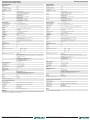
Technische Daten
Allgemeine Daten
Slave-Typ A/B-Slave
AS-Interface-Spezifikation V3.0
Erforderliche Master-Spezifikation ≥ V2.1
UL File Number E223772
Anzeigen/Bedienelemente
LED FAULT Fehleranzeige; LED rot
rot: Kommunikationsfehler bzw. Adresse ist 0
rot blinkend: Überlast interne Eingangsversorgung bzw. Überlast oder Leitungsbruch Ausgänge
LED INT Interne Eingangsversorgung aktiv; LED grün
LED PWR AS-Interface-Spannung; LED grün
grün: Spannung OK
grün blinkend: Adresse 0
LED AUX Ext. Hilfsspannung UAUX; Dual-LED grün/rot
grün: Spannung OK
rot: Spannung verpolt
LED IN Schaltzustand (Eingang); 4 LED gelb
LED OUT Schaltzustand (Ausgang); 3 LED gelb/rot
gelb: Ausgang aktiv
rot: Ausgangsüberlast oder Leitungsbruch
Elektrische Daten
Hilfsspannung (Ausgang) UAUX 20 ... 30 V DC PELV
Bemessungsbetriebsspannung Ue26,5 ... 31,6 V aus AS-Interface
Bemessungsbetriebsstrom Ie≤ 35 mA (ohne Sensoren) / max. 190 mA
Schutzklasse III
Überspannungsschutz UAUX, Ue: Überspannungskategorie III, sicher getrennte Spannungsversorgungen (PELV)
Eingang
Anzahl/Typ 4 Eingänge für 2- oder 3-Drahtsensoren (PNP), DC
Versorgung aus AS-Interface
Spannung 21 ... 31 V DC
Strombelastbarkeit ≤ 150 mA, überlast- und kurzschlussfest
Eingangsstrom ≤ 9 mA (intern begrenzt)
Schaltpunkt gemäß DIN EN 61131-2 (Typ 2)
0 (unbedämpft) ≤ 3 mA
1 (bedämpft) ≥ 5 mA
Signalverzögerung < 1 ms (Eingang/AS-Interface)
Ausgang
Anzahl/Typ 3 Elektronikausgänge, PNP, überlast- und kurzschlussfest
Versorgung aus externer Hilfsspannung UAUX
Strom O1 max. 3 A, O2/O3 max. 1,5 A, Summe 6 A (TB ≤ 40 °C)
O1 max. 2 A, O2/O3 max. 1 A, Summe 4 A (TB ≤ 60 °C)
Spannung ≥ (UAUX - 0,5 V)
Gebrauchskategorie DC-13
Programmierhinweise
Profil S-7.A.0
IO-Code 7
ID-Code A
ID1-Code 7
ID2-Code 0
Datenbit (Funktion über AS-Interface) Eingang Ausgang
D0 IN1 O1
D1 IN2 O2
D2 IN3 O3
D3 IN4 -
Parameterbit (programmierbar über AS-i) Funktion
P0 Kommunikationsüberwachung
P0 = 0 Überwachung = Aus, die Ausgänge behalten den Zustand bei Ausfall der Kommunikation
bei
P0 = 1 Überwachung = Ein, d. h. bei Ausfall der Kommunikation werden die Ausgänge stromlos
geschaltet (Grundeinstellung)
P1 Eingangsfilter
P1 = 0 Eingangsfilter ein, Impulsunterdrückung ≤2 ms
P1 = 1 Eingangsfilter aus (Grundeinstellung)
P2 Leitungsbrucherkennung Ausgänge
P2 = 0 Leitungsbrucherkennung ein
P2 = 1 Leitungsbrucherkennung aus (Grundeinstellung)
P3 nicht verwendet
Umgebungsbedingungen
Umgebungstemperatur -25 ... 60 °C (-13 ... 140 °F)
Lagertemperatur -25 ... 85 °C (-13 ... 185 °F)
Relative Luftfeuchtigkeit 85 % , nicht kondensierend
Klimatische Bedingungen Einsatz nur in Innenräumen
Einsatzhöhe ≤ 2000 m über NN
Verschmutzungsgrad 2
Mechanische Daten
Schutzart IP20
Anschluss abziehbare Klemmen
Bemessungsanschlussvermögen:
starr/flexibel (mit und ohne Aderendhülse): 0,25 mm2... 2,5 mm2
bei Mehrleiteranschluss von 2 Leitern gleichen Querschnitts:
flexibel mit Twin-Aderendhülse: 0,5 mm2... 1,5 mm2
Material
Gehäuse PA 66-FR
Masse 150 g
Befestigung Hutschiene
Anzugsmoment der Klemmschrauben 0,5 ... 0,6 Nm
Normen- und Richtlinienkonformität
Richtlinienkonformität
EMV-Richtlinie 2004/108/EG EN 61000-6-2:2005, EN 61000-6-4:2007, EN 50295:1999
Normenkonformität
Störfestigkeit EN 61000-6-2:2005, EN 61326-1:2006, EN 50295:1999
Störaussendung EN 61000-6-4:2007
Eingang EN 61131-2:2004
Schutzart EN 60529:2000
Feldbusstandard EN 50295:1999, IEC 62026-2:2006
Hinweise
Verbinden Sie bei Ein- und Ausgängen, die über das Modul aus AS-Interface oder über Hilfsenergie versorgt werden, keinen der
Signal- oder Versorgungsanschlüsse mit externen Potentialen.
Technical data
General specifications
Slave type A/B slave
AS-Interface specification V3.0
Required master specification ≥ V2.1
UL File Number E223772
Indicators/operating means
LED FAULT Error display; red LED
red: communication error, i.e. address is 0
red flashing: overload internal input supply, i.e. overload or lead interruption outputs
LED INT Internal input supply active; LED green
LED PWR AS-Interface voltage; green LED
green: voltage OK
flashing green: address 0
LED AUX ext. auxiliary voltage UA UX; dual LED green/red
green: voltage OK
red: reverse voltage
LED IN switching state (input); 4 LED yellow
LED OUT Switching state (output); 3 LED yellow/red
yellow: Output active
red: Output overload or lead breakage
Electrical specifications
Auxiliary voltage (output) UAUX 20 ... 30 V DC PELV
Rated operating voltage Ue26.5 ... 31.6 V from AS-Interface
Rated operating current Ie≤ 35 mA (without sensors) / max. 190 mA
Protection class III
Surge protection UAUX, Uin : Over voltage category III, safe isolated power supplies (PELV)
Input
Number/Type 4 inputs for 2- or 3-wire sensors (PNP), DC
Supply from AS-Interface
Voltage 21 ... 31 V DC
Current loading capacity ≤ 150 mA, overload and short-circuit protected
Input current ≤ 9 mA (limited internally)
Switching point according to DIN EN 61131-2 (Type 2)
0 (unattenuated) ≤ 3 mA
1 (attenuated) ≥ 5 mA
Signal delay < 1 ms (input/AS-Interface)
Output
Number/Type 3 electronic outputs, PNP, overload and short-circuit proof
Supply from external auxiliary voltage UAUX
Current O1 max. 3 A, O2/O3 max. 1.5 A, total 6 A (TB ≤ 40 °C)
O1 max. 2 A, O2/O3 max. 1 A, total 4 A (TB ≤ 60 °C)
Voltage ≥ (UA UX - 0.5 V)
Usage category DC-13
Programming instructions
Profile S-7.A.0
IO code 7
ID code A
ID1 code 7
ID2 code 0
Data bits (function via AS-Interface) input output
D0 IN1 O1
D1 IN2 O2
D2 IN3 O3
D3 IN4 -
Paramete r bits (programmable via AS-i) function
P0 Communication monitoring
P0 = 0 monitoring = off, the outputs maintain the status if communication fails
P0 = 1 monitoring = on, i.e. if communication fails, the outputs are deenergised (basic setting)
P1 Input filter
P1 = 0 input filter on, pulse suppression ≤2 ms
P1 = 1 input filter off (basic setting)
P2 Lead breakage outputs
P2 = 0 lead breakage on
P2 = 1 lead breakage off (basic setting)
P3 not used
Ambient conditions
Ambient temperature -25 ... 60 °C (-13 ... 140 °F)
Storage temperature -25 ... 85 °C (-13 ... 185 °F)
Relative humidity 85 % , noncondensing
Climatic conditions For indoor use only
Altitude ≤ 2000 m above MSL
Pollution Degree 2
Mechanical specifications
Degree of protection IP20
Connection removable terminals
rated connection capacity:
rigid/flexible (with and without wire-end ferrules): 0.25 mm2... 2.5 mm2
for multiple-wire connection with two wires of equal cross-section:
flexible with twin wire-end ferrules: 0.5 mm2... 1.5 mm2
Material
Housing PA 66-FR
Mass 150 g
Mounting DIN mounting rail
Tightening torque of clamping screws 0.5 Nm ... 0.6 Nm
Compliance with standards and directives
Directive conformity
EMC Directive 2004/108/EC EN 61000-6-2:2005, EN 61000-6-4:2007, EN 50295:1999
Standard conformity
Noise immunity EN 61000-6-2:2005, EN 61326-1:2006, EN 50295:1999
Emitted interference EN 61000-6-4:2007
Input EN 61131-2:2004
Degree of protection EN 60529:2000
Fieldbus standard EN 50295:1999, IEC 62026-2:2006
Notes
Do not connect inputs and outputs, which are supplied via the module from AS-interface or via auxiliary power, with power supply
and signal circuits with external potentials.
-
 1
1
-
 2
2


Pepperl+Fuchs VBA-4E3A-KE-ZEJ/E2L-LEN Bedienungsanleitung
- Typ
- Bedienungsanleitung
in anderen Sprachen
Verwandte Artikel
-
Pepperl+Fuchs VBA-4E4A-KE-ZEJQ/E2L Bedienungsanleitung
-
-
-
-
-
-
-
-
-