Pepperl+Fuchs UBE1000-18GM40A-SE2-V1 Bedienungsanleitung
- Typ
- Bedienungsanleitung

Ultraschall-Sensor
Ultrasonic Sensor
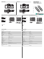
Abmessungen
Elektrischer Anschluss/Kurven/
Zusätzliche Informationen
Electrical Connection / Curves / Additional Information
Dimensions
Technische Daten
Technical data
UBE1000-18GM40A-SE2-V1
67,7
39,2
24,5
10
M12 x 1
M18 x 1
4
24
LED
-
67.7
39.2
24.5
10
M12 x 1
M18 x 1
4
24
LED
+UB
-UB
1
4
2
4
2
3
+UB
-UB
n.c.
1
3
(BN)
(BK)
(WH)
(BK)
(WH)
(BU)
(BN)
(BU)
U
U
Normsymbol/Anschluss:
(Version E2, pnp)
Empfänger:
Sender:
Adernfarben gemäß EN 60947-5-2.
Lerneingang
Schaltausgang
Testeingang
Steckverbinder V1
2
31
4
Abstand X [mm]
Charakteristische Ansprechkurve
Abstand Y [mm]
Hindernis: ebene Platte 100 mm x 100 mm
0 200 400 600 800 1000
20
15
10
5
0
-5
-10
-15
-20
X
Y
Abstand X [mm]
Hindernisgröße
min. Hindernisgröße d [mm]
mit Teach-In
ohne Teach-In
0 200 400 600 800 1000
80
70
60
50
40
30
20
10
0
X
d
distance X [mm]
Obstacle size
min. obstacle size d [mm]
with Teach-In
without Teach-In
0 200 400 600 800 1000
80
70
60
50
40
30
20
10
0
X
d
Distance X [mm]
Characteristic response curve
Distance Y [mm]
Obstacle: flat plate 100 mm x 100 mm
0 200 400 600 800 1000
20
15
10
5
0
-5
-10
-15
-20
X
Y
+UB
-UB
1
4
2
4
2
3
+UB
-UB
n.c.
1
3
(BN)
(BK)
(WH)
(BK)
(WH)
(BU)
(BN)
(BU)
U
U
Standard symbol/Connection:
(version E2, pnp)
Receiver:
Emitter:
Core colours in accordance with EN 60947-5-2.
Teaching input
Test input
Switching output
Connector V1
2
31
4
Part. No.:
Date:
205347
12/03/2009 DIN A3 -> DIN
45-2529C
Doc. No.:
Allgemeine Daten
Erfassungsbereich 15 ... 1000 mm
Normmessplatte 100 mm x 100 mm
Wandlerfrequenz ca. 255 kHz
Anzeigen/Bedienelemente
LED grün Power on
LED gelb Schaltzustand
LED rot Störung, Objekt unsicher
Elektrische Daten
Betriebsspannung UB10 ... 30 V DC , Welligkeit 10 %SS
Leerlaufstrom I0 20 mA
Eingang
Eingangstyp 1 Lerneingang
Luftstrecke: -UB ... +1 V, Objekt: +6 V ... +UB
Eingangsimpedanz: > 4,7 k Lernimpuls: 1 s
Ausgang
Ausgangstyp Schließer pnp
Bemessungsbetriebsstrom Ie200 mA , kurzschluss-/überlastfest
Spannungsfall Ud 3 V
Einschaltverzug ton < 5 ms
Schaltfrequenz f 100 Hz
Umgebungsbedingungen
Umgebungstemperatur -25 ... 70 °C (248 ... 343 K)
Lagertemperatur -40 ... 85 °C (233 ... 358 K)
Mechanische Daten
Schutzart IP67
Anschluss Gerätestecker V1 (M12 x 1), 4-polig
Material
Gehäuse Messing, vernickelt
Wandler Epoxidharz/Glashohlkugelgemisch; Schaum Polyurethan, Deckel PBT
Masse 25 g
Normen- und Richtlinienkonformität
Normenkonformität
Normen EN 60947-5-2:2007
IEC 60947-5-2:2007
General specifications
Sensing range 15 ... 1000 mm
Standard target plate 100 mm x 100 mm
Transducer frequency approx. 255 kHz
Indicators/operating means
LED green Power on
LED yellow switching state
LED red error, object uncertain
Electrical specifications
Operating voltage UB10 ... 30 V DC , ripple 10 %SS
No-load supply current I0 20 mA
Input
Input type 1 program input
free air path: -UB ... +1 V, object: +6 V ... +UB
input impedance: > 4,7 k program pulse: 1 s
Output
Output type NO pnp
Rated operational current Ie200 mA , short-circuit/overload protected
Voltage drop Ud 3 V
Switch-on delay ton < 5 ms
Switching frequency f 100 Hz
Ambient conditions
Ambient temperature -25 ... 70 °C (248 ... 343 K)
Storage temperature -40 ... 85 °C (233 ... 358 K)
Mechanical specifications
Protection degree IP67
Connection V1 connector (M12 x 1), 4-pin
Material
Housing brass, nickel-plated
Transducer epoxy resin/hollow glass sphere mixture; foam polyurethane, cover PBT
Mass 25 g
Compliance with standards and directives
Standard conformity
Standards EN 60947-5-2:2007
IEC 60947-5-2:2007

Adressen / Addresses / Adresses / Direcciónes / Indirizzi
Contact Pepperl+Fuchs GmbH · 68301 Mannheim · Germany · Tel. +49 621 776-4411 · Fax +49 621 776-27-4411 · E-mail: [email protected]l-fuchs.com
Worldwide Headquarters: Pepperl+Fuchs GmbH · Mannheim · Germany · E-mail: info@de.pepperl-fuchs.com
USA Headquarters: Pepperl+Fuchs Inc. · Twinsburg · USA · E-mail: fa-info@us.pepperl-fuchs.com
Asia Pacific Headquarters: Pepperl+Fuchs Pte Ltd · Singapore · E-mail: [email protected]perl-fuchs.com · Company Registration No. 199003130E
For more contact-adresses refer to the catalogue or internet: http://www.pepperl-fuchs.com
Function
A through-beam ultrasonic barrier always consists of a single emitter and a single receiver. The
function of a through-beam ultrasonic barrier is based in the interruption of the sound transmission
to the receiver by the object to be detected.
The emitter sends an ultrasonic signal that is evaluated by the receiver. If the signal is interrupted
or muted by the object to be detected, the receiver switches.
No electrical connections are required between the emitter and receiver.
The function of through-beam ultrasonic barriers is not dependent on the position of their installation.
We recommend, however, to install the emitter below in the case of vertical installations to prevent
the accumulation of dust particles.
Startup and parameterising
For easy alignment of emitter and receiver towards each other, the receiver is equipped with an
alignment aid. To activate the alignment aid, the TEACH-Input of the receiver (pin 2) has to be con-
nected to ground (-UB). The flashing frequency of the yellow LED indicates the strength of the recei-
ved ultrasonic signal. The better the alignment, the stronger the signal.
Simultaneously the ultrasonic barrier evaluates the signal strength of the unobstructed signal path
and generates the optimal switching threshold. When disconnecting the TEACH-input from -UB , this
threshold is stored non-volatile in the receivers memory. In case of clear ultrasonic path (no object),
only the receivers green LED is on.
TEACH-In of very small objects/obstacles
Like shown in the curve "obstacle size", the ultrasonic barrier offers the possibility to detect very
small objects at a distance of more than 300 mm.
- place the object to be detected in the desired distance inside the ultrasonic path
- connect TEACH-input of the receiver to +UB (yellow LED flashes slowly)
- disconnect TEACH-input
In case of successful TEACH-IN (object is detected reliable), the yellow LED is on and the taught
detection threshold is stored non-volatile to the receivers memory.
In case of unsuccessful TEACH-IN (object too small or too porous for ultrasonic sound),the red LED
flashes 5 times and the ultrasonic barrier continues normal operation with unmodified detection
threshold value.
Test function
For test purpose, the ultrasonic emitter is equipped with a test input. In normal operation mode (test
input not connected or connected to -UB), the green LED of the emitter is on. If the test input is con-
nected to +UB , the ultrasonic emitter gets deactivated and its LED changes into red. Simultaneously
the receiver switches and its yellow LED goes on.
LED yellow, flashing frequency Description
slowly (appr. 1.5 Hz) no signal
medium (appr. 3 Hz) weak signal
fast (appr. 9 Hz) strong signal
Funktionsweise
Eine Ultraschall-Einwegschranke besteht immer aus je einem Sender und einem Empfänger. Das
Funktionsprinzip der Ultraschall-Einwegschranken beruht auf der Unterbrechung der Schallübertra-
gung vom Sender zum Empfänger durch das zu erfassende Objekt (Hindernis).
Der Sender erzeugt ein Ultraschall-Signal, welches vom Empfänger ausgewertet wird. Wenn der Ul-
traschall durch das zu erfassende Objekt gedämpft oder unterbrochen wird, schaltet der Empfän-
ger.
Zwischen Sender und Empfänger sind keine elektrischen Verbindungen erforderlich.
Die Funktion der Ultraschall-Einwegschranken ist unabhängig von der Einbaulage. Es empfiehlt
sich dennoch, zur Vermeidung der Ablagerung von Schmutzpartikeln, bei vertikaler Einbaurichtung
den Sender unten zu montieren.
Inbetriebnahme und Parametrierung
Zur einfachen Ausrichtung von Sender und Empfänger zueinander, ist der Schrankenempfänger mit
einer Ausrichthilfe ausgestattet. Hierzu wird der Lerneingang des Empfängers (Pin 2) mit -UB ver-
bunden. Die Blinkfrequenz der gelben LED ist ein Maß für die Stärke des vom Sender empfangenen
Ultraschall-Signals. Je besser die gegenseitige Ausrichtung, desto stärker ist das Signal.
Gleichzeitig wird die Signalstärke der freien Luftstrecke ermittelt und daraus die optimale Ansprech-
schwelle der Ultraschall-Schranke generiert. Beim Trennen des Lerneingangs von -UB wird diese
Ansprechsschwelle nicht flüchtig im Empfänger gespeichert. Befindet sich kein Hindernis in der Ul-
traschall-Strecke leuchtet nur noch die grüne Empfänger-LED.
Einlernen sehr kleiner Objekte/Hindernisse
Wie in der Grafik „Hindernisgröße“ dargestellt, besteht die Möglichkeit bei einem Objektabstand
über 300 mm die Ultraschall-Schranke für die Detektion sehr kleiner Objekte einzulernen.
- das zu erfassende Hindernis im erforderlichen Abstand in der Ultraschall-Strecke positionieren
- Lerneingang des Empfängers mit +UB verbinden (LED gelb blinkt langsam)
- Lerneingang des Empfängers von +UB trennen
War das Lernen erfolgreich, d. h. das Hindernis wird sicher erkannt, so leuchtet die LED gelb und
die eingelernte Ansprechschwelle wird nicht flüchtig gespeichert. Bei nicht erfolgreichem Lernen
(Objekt zu klein oder zu durchlässig für Ultraschall) blinkt die rote LED 5 mal und die Ultraschall-
Schranke setzt den Betrieb mit unveränderter Einstellung der Ansprechschwelle fort.
Testfunktion
Der Sender ist zu Testzwecken mit einem Testeingang ausgestattet. Im Normalbetrieb (Testein-
gang offen oder an -UB) leuchtet die grüne LED. Wird der Testeingang mit +UB verbunden, so wird
der Ultraschall-Sender deaktiviert und die LED wechselt nach rot. Gleichzeitig schaltet der Ultra-
schall-Empfänger und seine LED gelb leuchtet.
LED gelb, Blinkfrequenz Bedeutung
langsam (ca. 1,5 Hz) kein Signal
mittel (ca. 3 Hz) schwaches Signal
schnell (ca. 9 Hz) starkes Signal
-
 1
1
-
 2
2


Pepperl+Fuchs UBE1000-18GM40A-SE2-V1 Bedienungsanleitung
- Typ
- Bedienungsanleitung
in anderen Sprachen
Verwandte Artikel
-
Pepperl+Fuchs UBE1000-18GM40-SE2-V1 Bedienungsanleitung
-
-
-
-
-
-
-
-