ECO Schulte FSA ECO SR-EFR Assembly Instructions Manual
- Typ
- Assembly Instructions Manual

1/18
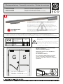
G
S
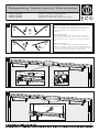
DIN rechts - spiegelbildlich
DIN right - mirror image
DIN droite - inverser l´illustration
F
Für die Montage dürfen ausschließlich Originalteile des Herstellers verwendet werden.
Die Montagearbeiten müssen gemäß Anleitung von einer qualifizierten Person
durchgeführt werden. Bei Nichtbeachtung entfällt jeglicher Garantieanspruch. Diese
Anleitung ist vom Monteur nach der Montage an den Betreiber weiterzugeben!
Only original parts have to be used. The assembly has to be made by a qualified person
according to the mounting instruction. In case of non-respect the guarantee is invalid. This
instruction is to be handed over to the operator by the fitter after assembly!
Impérativement utiliser la notice de montage fournie par le fabricant. La mise en œuvre et
le montage doivent être exécutés par du personnel qualifié. Le non respect de ces règles
annule catégoriquement tout droit de garantie. Cette instruction est à remettre par le
poseur à l’exploitant après montage.
Für die Montage sowie die Ventileinstellungen des Türschließers
beachten Sie bitte die dem Türschließer beiliegende separate
Montageanleitung.
Please refer to the enclosed assembly instruction of the doorcloser
for mounting as well as adjusting the valves of the doorcloser.
Pour le montage et le réglage des ferme-portes, merci d'utiliser la
notice de pose incluse séparément.
Leistungserklärung nach Verordnung (EU) Nr. 305/2011 finden Sie unter http://www.eco-schulte.de/leistungserklaerungen
Declaration of performance according to Regulation (EU) No 305/2011 see http://www.eco-schulte.de/declarationofperformance
Déclaration des performances conformément au règlement (UE) N° 305/2011 voir http://www.eco-schulte.de/declarationdesperformances
!
3-6 01 13 8
06
0432 - CPD - 0147
EN 1158:1997+A1:2002 /
AC:2006
0432 - CPD - 0143
EN 1155:1996+A1:2002 /
AC:2006
ECO Schulte GmbH & Co. KG
Iserlohner Landstraße 89
D-58706 Menden
3-6 31 13 5
max.
3,5mm
Bei Vollpanikfunktion ist eine Mitnehmerklappe
MK Basis 1 zu montieren.
Nicht im Lieferumfang enthalten!
With full panic function, a panic flap MK Basis 1
must be installed.
Not included in the delivery!
En cas de montage d'Anti-paniques sur les deux
vantaux, il faut utiliser l'entraineur MK Basis 1.
(N'est pas compris dans la livraison, à commander
séparément)
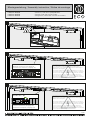
Montageanleitung / Assembly instruction / Notice de montage
FSA ECO SR-EFR
FSA ECO SR-EFR
FSA ECO SR-EFR
(DIN links / DIN rechts spiegelbildlich)
(DIN left / DIN right mirror image)
(DIN gauche / DIN droite inverser l‘illustration)
© ECO Schulte GmbH & Co. KG / Änderungen vorbehalten! / FSA SR-EFR / MTS00566 / 33920000566 / Index: a

2/18
1a
942
93
546
23
142
160
16
42
36
23
595
109,5
142
160
16
42
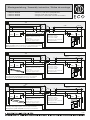
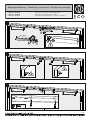
Direktmontage (ohne Unterprofil - Lochgruppe 93/546mm, 595/109,5mm)
Direct mounting (without underprofile - hole group 93/546mm, 595/109,5mm)
Montage direct (sans sous profil - perçage 93/546mm, 595/109,5mm)
Bohrung für elektrischen
Anschluss (230V)
Drilling for electrical
connection (230V)
Alésage pour raccordement
électrique (230V)
1b
120
428,5
23
142
160
36
23
428,5
142
160
16
42
Bohrung für elektrischen
Anschluss (230V)
Drilling for electrical
connection (230V)
Alésage pour raccordement
électrique (230V)
Montage mit Standardprofil 20mm (Lochgruppe 120/428,5mm)
Mounting with standardprofile 20mm (hole group 120/428,5mm)
Montage avec profil standard 20mm (perçage 120/428,5mm)
120
1c
120
428,5
10
142
160
36
10
428,5
142
160
16
42
Bohrung für elektrischen
Anschluss (230V)
Drilling for electrical
connection (230V)
Alésage pour raccordement
électrique (230V)
120
Montage mit Adaptionsprofil 30mm (Lochgruppe 120/428,5mm)
Mounting with adaptor plate 30mm (hole group 120/428,5mm)
Montage avec profil d’adaptation 30mm (perçage 120/428,5mm)
Bohrung für zusätzliche Anschlüsse
Drilling for additional electrical
connections
Alésage pour les connexions
électriques supplémentaires
optional / optional / optionnelle
ø10
ø10
784
942
16
42
Bohrung für zusätzliche Anschlüsse
Drilling for additional electrical
connections
Alésage pour les connexions
électriques supplémentaires
optional / optional / optionnelle
ø10
ø10
784
(optional, optional, optionnelle)
(optional, optional, optionnelle)
942
16
42
Bohrung für zusätzliche Anschlüsse
Drilling for additional electrical
connections
Alésage pour les connexions
électriques supplémentaires
optional / optional / optionnelle
ø10
ø10
784
min. 10mm
min. 10mm
min. 10mm
Montageanleitung / Assembly instruction / Notice de montage
FSA ECO SR-EFR
FSA ECO SR-EFR
FSA ECO SR-EFR
(DIN links / DIN rechts spiegelbildlich)
(DIN left / DIN right mirror image)
(DIN gauche / DIN droite inverser l‘illustration)

3/18
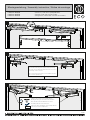
2a
2
2b
2
M5x20
4,8x30
M5x20
4,8x30
M5x20
4,8x30
M5x20
4,8x30
1
1
2
2c
2
M5x20
4,8x30
M5x20
4,8x30
1
1
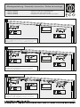
Direktmontage (ohne Unterprofil - Lochgruppe 93/546mm, 595/109,5mm)
Direct mounting (without underprofile - hole group 93/546mm, 595/109,5mm)
Montage direct (sans sous profil - perçage 93/546mm, 595/109,5mm)
Montage mit Standardprofil 20mm (Lochgruppe 120/428,5mm)
Mounting with standardprofile 20mm (hole group 120/428,5mm)
Montage avec profil standard 20mm (perçage 120/428,5mm)
Montage mit Adaptionsprofil 30mm (Lochgruppe 120/428,5mm)
Mounting with adaptor plate 30mm (hole group 120/428,5mm)
Montage avec profil d’adaptation 30mm (perçage 120/428,5mm)
230V AC
+15%/-10%
3 x 1,5mm²
230V AC
+15%/-10%
3 x 1,5mm²
230V AC
+15%/-10%
3 x 1,5mm²
M5x20
4,5x35
M5x20
4,5x35
(optional, optional, optionnelle)
(optional, optional, optionnelle)
Montageanleitung / Assembly instruction / Notice de montage
FSA ECO SR-EFR
FSA ECO SR-EFR
FSA ECO SR-EFR
(DIN links / DIN rechts spiegelbildlich)
(DIN left / DIN right mirror image)
(DIN gauche / DIN droite inverser l‘illustration)

4/18
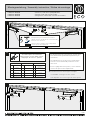
3a
3b
3c
1
2
3
1
2
3
1
2
3
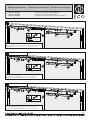
Direktmontage (ohne Unterprofil - Lochgruppe 93/546mm, 595/109,5mm)
Direct mounting (without underprofile - hole group 93/546mm, 595/109,5mm)
Montage direct (sans sous profil - perçage 93/546mm, 595/109,5mm)
Montage mit Standardprofil 20mm (Lochgruppe 120/428,5mm)
Mounting with standardprofile 20mm (hole group 120/428,5mm)
Montage avec profil standard 20mm (perçage 120/428,5mm)
Montage mit Adaptionsprofil 30mm (Lochgruppe 120/428,5mm)
Mounting with adaptor plate 30mm (hole group 120/428,5mm)
Montage avec profil d’adaptation 30mm (perçage 120/428,5mm)
M5x12
M5x12
M5x20
4,5x35
(optional, optional, optionnelle)
(optional, optional, optionnelle)
Montageanleitung / Assembly instruction / Notice de montage
FSA ECO SR-EFR
FSA ECO SR-EFR
FSA ECO SR-EFR
(DIN links / DIN rechts spiegelbildlich)
(DIN left / DIN right mirror image)
(DIN gauche / DIN droite inverser l‘illustration)

2a
5/18
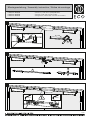
4
5
2a6
SW2,5
Die elektrischen Anschlüsse müssen gemäß Anleitung von einer qualifizierten
Person durchgeführt werden. Bei Nichtbeachtung entfällt jeglicher
Garantieanspruch. Diese Anleitung ist vom Monteur nach der Montage an
den Betreiber weiterzugeben!
The electrical installation has to be made by a qualified person according to
the mounting instruction. In case of non-respect the guarantee is invalid. This
instruction is to be handed over to the operator by the fitter after assembly!
La mise en œuvre,la connection électrique et le montage doivent être
exécutés par du personnel qualifié. Le non respect de ces règles annule
catégoriquement tout droit de garantie. Cette instruction est à remettre par le
poseur à l’exploitant après montage.
230 V AC +15% / -10%
Elektrische Anschlüsse (siehe S. 12)
Electrical connections (see page 12)
Connexions électriques (voir page 12)
Externe Anschlüsse (siehe S. 12)
External connections (see page 12)
Connectiones externes (voir page 12)
Montageanleitung / Assembly instruction / Notice de montage
FSA ECO SR-EFR
FSA ECO SR-EFR
FSA ECO SR-EFR
(DIN links / DIN rechts spiegelbildlich)
(DIN left / DIN right mirror image)
(DIN gauche / DIN droite inverser l‘illustration)

6/18
8
3
2
2
3
9
2a7
1
1
3
SW 2,5
SG/CS/VF
2
1
Schließen der Ventile wie in der beiliegenden
Montageanleitung des Türschließers beschrieben.
Close the valves as described in the enclosed
assembly instruction of the doorcloser.
Fermer les valves de réglages comme indiqué dans la
notice de pose incluse séparément.
2
M3x4
Für die Montage des Türschließers beachten Sie bitte die
dem Türschließer beiliegende separate Montageanleitung.
Refer to the enclosed assemby instruction of the doorcloser
for mounting of the doorcloser.
Pour le montage des ferme-portes, merci d'utiliser la notice
de pose incluse séparément.
Montageanleitung / Assembly instruction / Notice de montage
FSA ECO SR-EFR
FSA ECO SR-EFR
FSA ECO SR-EFR
(DIN links / DIN rechts spiegelbildlich)
(DIN left / DIN right mirror image)
(DIN gauche / DIN droite inverser l‘illustration)

7/18
2
10
2a12
1
2
1
2
Öffnen der Ventile wie in der beiliegenden
Montageanleitung des Türschließers beschrieben.
Open the valves as described in the enclosed assembly
instruction of the doorcloser.
Ouvrir les valves de réglages comme indiqué dans la
notice de pose incluse séparément.
SW 2,5
SG/CS/VF
2
1
11
Die Einstellungen des Türschließers sind der dem
Türschließer beiliegenden Montageanleitung zu
entnehmen.
The adjustments of the doorcloser can be taken
from the enclosed assembly instruction of the
doorcloser.
Pour le réglage des ferme-portes , merci d'utiliser
la notice de pose incluse séparément.
nicht bei allen Türschließertypen verfügbar
not available on all types of door closers
Pas disponible sur tous les types de ferme-portes
*
Einstellungen Türschließer
Adjustments of the door closer
Reglages du ferme - portes
SK
ES
ÖD
SG
Endschlag
Öffnungs-
dämpfung
Schließkraft
CF
Abkürzungen
Abbreviations Abréviations
Closing speed
LS
BC
CS
Latching speed
Back check
Closing force
Vitesse de
fermeture
FF
CF
FO
VF
Coup final
Frein á
l’ouverture
Force de
fermeture
Schließ-
geschwindigkeit
SV
Schließ-
verzögerung
DA
Delay action
TF
Temporisation à
la fermeture
*
*
Montageanleitung / Assembly instruction / Notice de montage
FSA ECO SR-EFR
FSA ECO SR-EFR
FSA ECO SR-EFR
(DIN links / DIN rechts spiegelbildlich)
(DIN left / DIN right mirror image)
(DIN gauche / DIN droite inverser l‘illustration)

8/18
2a
13
X - 1mm
2
2a14
2a15
1
X
1
2
90°
3
SW2,5
SW2,5
Montageanleitung / Assembly instruction / Notice de montage
FSA ECO SR-EFR
FSA ECO SR-EFR
FSA ECO SR-EFR
(DIN links / DIN rechts spiegelbildlich)
(DIN left / DIN right mirror image)
(DIN gauche / DIN droite inverser l‘illustration)

18
9/18
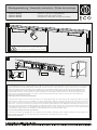
Funktionsprüfung SR
Beide Türen ca. 60° öffnen, Gangflügel (G) muss geöffnet
bleiben. Standflügel (S) schließt. Gangflügel (G) darf erst ab
einem Schließwinkel des Standflügels (S) von ca. 30°
schließen.
Functionality test SR
Open both doors approx. 60°, active leaf (G) has to remain
open. Passive leaf (S) closes. Active leaf (G) is only allowed to
close if the passive leaf (S) reaches a closing angle of approx.
30°.
Test du sélecteur SR
Ouvrir les deux vantaux à 60°, le vantail principal (G) doit se
maintenir en position ouverte. Le vantail secondaire (S) doit se
fermer. Le vantail principal (G) doit se fermer à partir d’un angle
de fermeture du vantail secondaire (S) à partir de 30°.
G
S
2
3
G
S
1
60°
60°
30°
2a16
17
Click
Y
Montageanleitung / Assembly instruction / Notice de montage
FSA ECO SR-EFR
FSA ECO SR-EFR
FSA ECO SR-EFR
(DIN links / DIN rechts spiegelbildlich)
(DIN left / DIN right mirror image)
(DIN gauche / DIN droite inverser l‘illustration)

10/18
19
2
Y - 8mm
1
20
21
M3x6
Montageanleitung / Assembly instruction / Notice de montage
FSA ECO SR-EFR
FSA ECO SR-EFR
FSA ECO SR-EFR
(DIN links / DIN rechts spiegelbildlich)
(DIN left / DIN right mirror image)
(DIN gauche / DIN droite inverser l‘illustration)

11/18
70°
130°
23
Die Feststellanlage ist für einen Türöffnungswinkel von 90° vormontiert. Der Öffnungswinkel lässt sich durch Verschieben der Feststelleinheit
in Richtung Türmitte bis auf 70° und Richtung Türbänder bis auf 130° verstellen. Hierzu wird die Tür auf den gewünschten Feststellwinkel
geöffnet und festgesetzt. Zum Verschieben der Feststelleinheit muss die Klemmschraube gelöst werden. Die Feststelleinheit dann auf
Anschlag an das Gleitstück schieben und Klemmschraube anziehen. Beim max. Türöffnungswinkel kleiner 90° kann das Gleitstück die
Klemmschraube verdecken. In diesem Falle muss die Feststelleinheit vor dem Öffnen und Festsetzen der Tür auf Anschlag in Richtung
Türmitte nach Lösen der Klemmschraube verschoben werden. Klemmschraube wieder festziehen und wie vorher beschrieben den
gewünschten Feststellwinkel einstellen.
Funktionsprüfung der Feststellung durchführen!
The slide rail with hold-open function is premounted for a door opening angle of 90°. The open angle can be changed up to 70° by moving the
hold open unit in the direction of the door middle. It can also be changed up to 130° by moving the hold open unit in the direction of the door
hinges. This is achieved by opening the door until the requested opening angle is achieved and fixing it in this position. In order to move the
hold open unit, you have to loosen the fixing screw. Move the hold-open unit till dead stop of the sliding block and tighten the fixing screw. In
case the max. door opening angle is smaller than 90°, the sliding block might cover the fixing screw. In this case, the hold-open unit has to be
moved till dead stop in direction of door middle after fixing screw has been loosened. This has to be done before the door is opened and fixed
in wished position. Tighten fixing screw and adjust (as described above) the requested hold-open angle.
Carry out a functionality test of hold-open function.
Le sélecteur de fermeture est pré-disposé pour un angle d’ouverture de 90°. Cet angle peut être modifié en dévissant les vis pointeaux et en
déplacant l’arrêt de 70 à 130°. De cette façon la porte peut être maintenue à l’angle d’ouverture souhaité.
Tester le fonctionnement.
SW 2,5
22
Funktionsprüfung des Rauchmelders
Functional check of smoke detector
Test fonctionnel de détecteur de fumée
Montageanleitung / Assembly instruction / Notice de montage
FSA ECO SR-EFR
FSA ECO SR-EFR
FSA ECO SR-EFR
(DIN links / DIN rechts spiegelbildlich)
(DIN left / DIN right mirror image)
(DIN gauche / DIN droite inverser l‘illustration)

12/18
24
24V DC
+15%/-10%
IY (ST) Y 2x2x0,6 /
IY (ST) Y 2x2x0,8
230V AC
+15%/-10%
(optional, optional, optionnelle)
Anschluss von externen Wandhaftmagneten (bei Entfall der Feststelleinheit)
Connection of external wall solenoids (when omitting the hold open unit)
Connection de ventouses de rétention (en cas de suppression de la ventouse intégrée)
L PE N
Blau
Blue
Bleu
Braun
Brown
Brun
Anschluss des Schutzleiters
Connecting the protective earth conductor
Connexion du conducteur de protection
26
25
Grün zu 6
Green to 6
Vert à 6
Braun zu Minus (-)
Brown to minus (-)
Brun à moins (-)
Elektrische Anschlüsse (siehe S. 13-16)
Electrical connections (see pages 13-16)
Connexions électriques (voir pages 13-16)
Montageanleitung / Assembly instruction / Notice de montage
FSA ECO SR-EFR
FSA ECO SR-EFR
FSA ECO SR-EFR
(DIN links / DIN rechts spiegelbildlich)
(DIN left / DIN right mirror image)
(DIN gauche / DIN droite inverser l‘illustration)

13/18
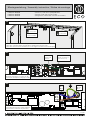
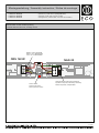
interner Taster
internal push button
bouton poussoir interne
wichtiges Bauteil, zwingend erforderlich!
important component, absolutely necessary!
élément important, indispensable!
NAG 02
ORS 142 W
Brücke 1 auf 5. WICHTIG!
Bridge 1 to 5. IMPORTANT!
Pont 1 sur 5. IMPORTANT!
K
1
B
+
-
Rauchschaltzentrale Auslieferungszustand
Smoke switch control unit factory setting
Centrale détection de fumée, montage d‘usine
Montageanleitung / Assembly instruction / Notice de montage
FSA ECO SR-EFR
FSA ECO SR-EFR
FSA ECO SR-EFR
(DIN links / DIN rechts spiegelbildlich)
(DIN left / DIN right mirror image)
(DIN gauche / DIN droite inverser l‘illustration)

14/18
interner Taster
internal push button
bouton poussoir interne
NAG 02
ORS 142 W
K
1
B
+
-
Brücke 1 auf 5. WICHTIG!
Bridge 1 to 5. IMPORTANT!
Pont 1 sur 5. IMPORTANT!
wichtiges Bauteil, zwingend erforderlich!
important component, absolutely necessary!
élément important, indispensable!
L
HAT
S
Ö
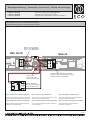
externer Handtaster
external hand push button
bouton poussoir externe
Step 1: Re-wiring of the delivery status
Remove cable of the internal push button from slot 1 of NAG
02 and connect it to slot K of NAG 02
Step 2: Connecting the external hand push button
Connect the external hand push button to slot K and
to slot 1 of NAG 02
Etape 1: Décâblage du montage d'usine
Déconnecter le câble du bornier 1 de NAG 02 et
connecter au bornier K du NAG 02
Etape 2 : Connexion de bouton poussoir externe
Connecter le bouton poussoir externe aux
borniers K et 1 de NAG 02
Schritt 1: Umverdrahten des Auslieferungszustandes
Kabel des internen Tasters vom Steckplatz 1 am NAG 02
entfernen und auf Steckplatz K am NAG 02 stecken
Schritt 2: Anklemmen des externen Handtasters
Kabel des externen Tasters auf Steckplatz K und
Steckplatz 1 am NAG 02 stecken
Rauchschaltzentrale + externen Taster
Smoke switch control unit + external hand push button
Centrale détection de fumée + bouton poussoir externe
Montageanleitung / Assembly instruction / Notice de montage
FSA ECO SR-EFR
FSA ECO SR-EFR
FSA ECO SR-EFR
(DIN links / DIN rechts spiegelbildlich)
(DIN left / DIN right mirror image)
(DIN gauche / DIN droite inverser l‘illustration)

15/18
interner Taster
internal push button
bouton poussoir interne
wichtiges Bauteil, zwingend erforderlich!
important component, absolutely necessary!
élément important, indispensable!
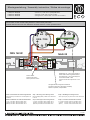
Die Brücke von 1 auf 5 muss immer im
letzten ORS / TDS eingesetzt werden!
The bridge from 1 to 5 must always be
set in the last ORS / TDS!
Toujours connecter le pont entre 1 et 5
à fin.
K
1
B
+
-
-
+
3
BUS
ORS / TDS
2
6
5
1
4
-
+
3
6
BUS
ORS / TDS
5
1
4
2
Rauchschaltzentrale mit Deckenmelder + internen Taster
Smoke switch control unit with ceiling detectors + internal hand push button
Centrale détection de fumée avec détecteurs de fumée externes + bouton poussoir interne
NAG 02
ORS 142 W
Schritt 1: Umverdrahten des Auslieferungszustandes
5 entfernen
Brücke (schwarz) vom ORS 142 W vom Steckplatz 1 zu
Schritt 2: Anklemmen der externen Deckenmelder
1 + (rot) vom ORS / TDS auf 1 ORS 142 W
2 - (blau) vom ORS / TDS auf 2 ORS 142 W
4 (braun) vom ORS / TDS auf 5 ORS 142 W
Step 1: Re-wiring of the delivery status
Remove bridge (black) of ORS 142 W from slot 1
Step 2: Connecting the external ceiling detectors
1 + (red) from ORS / TDS to 1 ORS 142 W
2 - (blue) from ORS / TDS to 2 ORS 142 W
4 (brown) from ORS / TDS to 5 ORS 142 W
4 (brun) de ORS / TDS sur 5 de ORS 142 W
Etape 2 : Connexion des détecteurs externes
2 - (bleu) de ORS / TDS sur 2 de ORS 142 W
1 + (rouge) de ORS / TDS sur 1 de ORS 142 W
Ôter le pont le pont (noir) du bornier 1 à 5 de ORS 142 W
Etape 1: Décâblage du montage d'usine
to slot 5
Montageanleitung / Assembly instruction / Notice de montage
FSA ECO SR-EFR
FSA ECO SR-EFR
FSA ECO SR-EFR
(DIN links / DIN rechts spiegelbildlich)
(DIN left / DIN right mirror image)
(DIN gauche / DIN droite inverser l‘illustration)

16/18
L
HAT
S
Ö
-
+
3
4
BUS
ORS / TDS
2
6
5
1
-
+
3
6
BUS
ORS / TDS
5
1
4
2
externer Handtaster
external hand push button
bouton poussoir externe
interner Taster
internal push button
bouton poussoir interne
wichtiges Bauteil, zwingend erforderlich!
important component, absolutely necessary!
élément important, indispensable!
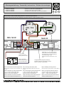
Die Brücke von 1 auf 5 muss immer im
letzten ORS / TDS eingesetzt werden!
The bridge from 1 to 5 must always be
set in the last ORS / TDS!
Toujours connecter le pont entre 1 et 5
à fin.
NAG 02
ORS 142 W
K
1
B
+
-
Rauchschaltzentrale mit Deckenmelder + externen Taster
Smoke switch control unit with ceiling detectors + external hand push button
Centrale détection de fumée avec détecteurs de fumée externes + bouton poussoir externe
Etape 1: Décâblage du montage d'usine
Ôter le pont le pont (noir) du bornier 1 à 5 de ORS 142
Etape 2 : Connexion des détecteurs externes
1 + (rouge) de ORS / TDS sur 1 de ORS 142 W
2 - (bleu) de ORS / TDS sur 2 de ORS 142 W
4 (brun) de ORS / TDS sur K de NAG 02
Etape 3: Connexion de bouton poussoir externe
Connecter le bouton poussoir externe aux borniers 5
de ORS 142 W et K de NAG 02
Step 1: Re-wiring of the delivery status
Remove bridge (black) od ORS 142 W from slot 1
Step 2: Connecting the external ceiling detectors
1 + (red) from ORS / TDS to 1 ORS 142 W
2 - (blue) from ORS / TDS to 2 ORS 142 W
4 (brown) from ORS / TDS to K NAG 02
Step3: Connecting the external hand push button
Connect the external hand push button to slot 5 of
ORS 142 W and to slot K of NAG 02
Schritt 1: Umverdrahten des Auslieferungszustandes
Brücke (schwarz) vom ORS 142 W vom Steckplatz 1 zu 5
entfernen
Schritt 2: Anklemmen der externen Deckenmelder
1 + (rot) vom ORS / TDS auf 1 ORS 142 W
2 - (blau) vom ORS / TDS auf 2 ORS 142 W
4 (braun) vom ORS / TDS auf K NAG 02
Schritt 3: Anklemmen des externen Handtasters
Kabel des externen Tasters auf Steckplatz 5 am
ORS 142 W und Steckplatz K am NAG 02 neu belegen
to slot 5
Montageanleitung / Assembly instruction / Notice de montage
FSA ECO SR-EFR
FSA ECO SR-EFR
FSA ECO SR-EFR
(DIN links / DIN rechts spiegelbildlich)
(DIN left / DIN right mirror image)
(DIN gauche / DIN droite inverser l‘illustration)

17/18
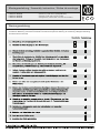
Überprüfung der Leichtgängigkeit der Tür.
1.
Kontrolle der schließfolgerichtigen Selbstschließung (Standflügel vor Gangflügel).
Visuelle Kontrolle der Anlage, feststellen augenscheinlicher Defekte und äußerer
Beschädigungen.
Überprüfung der mechanischen Stabilität bzw. Befestigung und Leichtgängig-
keit aller Anlagenteile. Ggf. nachjustieren bzw. nachspannen der Einstell- und
Befestigungselemente.
Überprüfung der Einstellungen am Türschließer, z. B. Schließgeschwindigkeit, Endschlag,
Öffnungsdämpfung, Schließverzögerung, selbstschließende Eigenschaft.
Kontrolle der Bremsmimik (Gangflügel) auf Abnutzung / Verschleiß.
Verschlissene Teile (speziell Bremskeil, Verdrehkeil - rot) sind auszutauschen.
Defekte Produkte und / oder Bauteile sind sofort zu ersetzen, sobald eine einwandfreie
Funktion nicht mehr sichergestellt ist.
Kontrolle auf Verschmutzungen und mögliche Beeinträchtigungen aus dem Umfeld der
Anlage.
Säubern und entfetten der Gleitschiene, speziell Laufwege der Gleitschuhe /
Bremsbereich.
Säubern und entfetten aller beweglichen Bauteile (außer Gleitschuhe in den Gleitschienen).
Anbringen eines Prüfvermerks.
Ausstellen des Wartungsberichtes.
Normativ (EN 1158) werden 25.000 Öffnungszyklen über die Vollpanikfunktion (Standflügel öffnet Gangflügel über
Mitnehmerklappe) als Prüfzyklen definiert.
SR / SR BG
2.
3.
4.
5.
6.
7.
8.
9.
10.
11.
12.
Wartungshinweise für ECO Schließfolgeregelungen SR und SR BG
an Vollpaniktüren
Aus Art und Nutzung der Drehflügeltüren ergeben sich Umfang und Häufigkeit von Wartungsarbeiten. Bei durch-
schnittlicher Belastung erachtet der Hersteller zumindest eine jährliche Wartung als notwendig. Häufigere Belastung
oder höhere Gewichte als in EN 1158 bzw. durch den Hersteller vorgegeben, erfordern kleinere Intervalle.
Montageanleitung / Assembly instruction / Notice de montage
FSA ECO SR-EFR
FSA ECO SR-EFR
FSA ECO SR-EFR
(DIN links / DIN rechts spiegelbildlich)
(DIN left / DIN right mirror image)
(DIN gauche / DIN droite inverser l‘illustration)

18/18
Wartungsanleitung
Aus Art und Nutzung der Drehflügeltüren ergeben sich Umfang und Häufigkeit von Wartungsarbeiten. Bei durch-
schnittlicher Belastung erachtet der Hersteller zumindest eine jährliche Wartung als notwendig. Häufigere Belastung
erfordert kleinere Intervalle.
Montageanleitung / Assembly instruction / Notice de montage
FSA ECO SR-EFR
FSA ECO SR-EFR
FSA ECO SR-EFR
(DIN links / DIN rechts spiegelbildlich)
(DIN left / DIN right mirror image)
(DIN gauche / DIN droite inverser l‘illustration)
-
 1
1
-
 2
2
-
 3
3
-
 4
4
-
 5
5
-
 6
6
-
 7
7
-
 8
8
-
 9
9
-
 10
10
-
 11
11
-
 12
12
-
 13
13
-
 14
14
-
 15
15
-
 16
16
-
 17
17
-
 18
18


ECO Schulte FSA ECO SR-EFR Assembly Instructions Manual
- Typ
- Assembly Instructions Manual
in anderen Sprachen
- English: ECO Schulte FSA ECO SR-EFR
- français: ECO Schulte FSA ECO SR-EFR
Andere Dokumente
-
norbar 34398 Referenzhandbuch
-
ECO FTA ECO-Vent Assembly Instruction Manual
-
AVENTICS Locking units LU1/LU2 for pneumatic cylinders, diameter 32-100 Bedienungsanleitung
-
-
Maico EFR Series Mounting And Operating Instructions
-
-
Tamiya TT-01D Type-E Bedienungsanleitung
-
-
-
Nikon ファーブル フォト Benutzerhandbuch