Panasonic cy pad 1003 n Bedienungsanleitung
- Kategorie
- Autolautsprecher
- Typ
- Bedienungsanleitung
Dieses Handbuch eignet sich auch für

4 Channel Power Amplifi er
Model:
CY-PA4003N
2 Channel Power Amplifi er
Model:
CY-PA2003N
Digital Mono Amplifi er
Model:
CY-PAD1003N
Operating Instructions
Bedienungsanleitung
Manuel d’instructions
Manuale di istruzioni
Manual de Instrucciones
Please read these instructions carefully before using this product and keep this manual for future reference.
Bitte lesen Sie diese Bedienungsanleitung vor der Verwendung dieses Produktes aufmerksam durch und bewahren Sie sie
danach für spätere Nachschlagzwecke sorgfältig auf.
Prière de lire ces instructions attentivement avant d’utiliser le produit et garder ce manuel pour l’utilisation ultérieure.
Si prega di leggere attentamente queste istruzioni prima di usare questo prodotto e di conservare questo manuale per usi futuri.
Lea con atención estas instrucciones antes de utilizar el producto y guarde este manual para poderlo consultar en el futuro.
(CY-PA4003N)

2
English
CY-PA4003N/PA2003N/PAD1003N
3
English
CY-PA4003N/PA2003N/PAD1003N
Read the operating instructions for the unit and all other
components of your car audio system carefully before
using the system. They contain instructions about
how to use the system in a safe and effective manner.
Panasonic assumes no responsibility for any problems
resulting from failure to observe the instructions given
in this manual.
This manual uses pictographs to show you how to use
the product safely and to alert you to potential dangers
resulting from improper connections and operations.
The meaning of the pictographs are explained below.
It is important that you fully understand the meanings
of the pictographs in order to use this manual and the
system properly.
Safety Information
This pictograph intends to alert you to
the presence of important operating
instructions. Failure to heed the
instructions may result in severe injury
or death.
This pictograph intends to alert you to
the presence of important operating
instructions. Failure to heed the
instructions may result in injury or
material damage.
Warning
Caution
Observe the following warnings when using the
unit.
Use the proper power supply.
This
product
is designed for operation with a negative
grounded 12 V DC battery system. Never operate this
product with other battery system, especially a 24 V DC
battery system.
Do not disassemble or modify the unit.
Do not disassemble, modify the unit or attempt to
repair the product yourself. If the product needs to
be repaired, consult your dealer or an authorised
Panasonic Service Centre.
Do not use the unit when it is out of order.
If the unit is out of order (no power, no sound) or in an
abnormal state (has foreign objects in it, is exposed to
water, is smoking, or smells), turn it off immediately
and consult your dealer.
Refer fuse replacement to qualifi ed service
personnel.
When the fuse blows out, eliminate the cause and have
it replaced with the fuse prescribed for this unit by a
qualifi ed service engineer. Incorrect replacement of
the fuse may lead to smoke, fi re, and damage to the
product.
When replacing one fuse which has blown, replace
other fuses at the same time.
In some cases, fuses may deteriorate without failing.
Using different substitutes or fuses with higher ratings,
or connecting the unit directly without a fuse, could
cause fi re or damage to the unit. If the replacement fuse
fails, contact your nearest Panasonic Service Centre for
service.
Warning
Observe the following warnings when installing.
Disconnect the lead from the negative () battery
terminal before installation.
Wiring and installation with the negative () battery
terminal connected may cause electrical shock and
injury due to a short circuit.
Some cars equipped with the electrical safety
system have specifi c procedures of battery terminal
disconnection.
FAILURE TO FOLLOW THE PROCEDURE MAY
LEAD TO THE UNINTENDED ACTIVATION OF THE
ELECTRICAL SAFETY SYSTEM RESULTING IN
DAMAGE TO THE VEHICLE AND PERSONAL INJURY
OR DEATH.
Never use safety-related components for
installation, grounding, and other such functions.
Do not use safety-related vehicle components (fuel
tank, brake, suspension, steering wheel, pedals
airbags, etc.) for wiring or fi xing the product or its
accessories.
Check for piping, gasoline tank, electric wiring, and
other items before installing the product.
If you need to open a hole in the vehicle chassis to
attach or wire the product, fi rst check where the wire
harness, gasoline tank, and electric wiring are located.
Then open the hole from outside if possible.
After installation and wiring, you should check the
normal operation of other electrical equipment.
The continuation of their using in abnormal conditions
may cause fi re, electrical shock or a traffi c accident.
In the case of installation to an airbag-equipped
car, confi rm warnings and cautions of the vehicle
manufacturer before installation.
Make sure the leads do not interfere with driving or
getting in and out of the vehicle.
Failure to heed this caution may result in an accident
and/or injury.
Warning
Observe the following cautions when using this
unit.
Turn off the power supply before changing the
switch setting.
Keep the sound volume at an appropriate level.
Keep the volume level low enough to be aware of road
and traffi c conditions while driving.
This unit is designed for use exclusively in
automobiles.
Do not operate the unit for a prolonged period with
the engine turned off.
Operating the audio system for a long period of time
with the engine turned off will drain the battery.
Do not expose the unit to direct sunlight or
excessive heat.
Otherwise these will raise the interior temperature
of the unit, and it may lead to smoke, fi re, or other
damage to the unit.
Do not use the product where it will be exposed to
water, moisture, or dust.
Exposure of the unit to water, moisture, or dust may
lead to smoke, fi re, or other damage to the unit. Make
especially sure that the unit does not get wet in car
washes or on rainy days.
Stop to use the unit when the red indicator
(PROTECT) lights up.
If the red indicator lights up, this unit will
automatically shut down. Confi rm the speaker and
other audio system’s wiring.
Do not touch the heat dissipation region of the
amplifi er.
If this unit is operated at a high output continuously,
the upper side of the unit will get very hot. Do not
touch it nor place anything on top of the unit.
Contact your local dealer for information about
battery capacity. (If there is not enough battery
capacity, increase the number of batteries.)
Depending on the way you use this unit, (using at
high volume for extended periods, increasing the
number of amplifi ers etc. ) there may be insuffi cient
battery capacity. There is a danger that the battery will
run fl at, or other electronic parts may stop operating.
Do not knock anything against this unit when
loading or unloading objects from the trunk.
Doing so will cause damage to this unit.
Caution
This unit cannot be used alone.
This unit is a power amplifi er for use with Panasonic
car audio products and speakers.
For more details about safety information, refer to
the operating instructions for the connected devices.
Please follow the laws and regulations
of your province or country for
installation of the unit.
For power connection, use the optional power cord
specially designed for use with Panasonic car-audio/
AV system.
Power cord kit (option): CA-PAC75

4
English
CY-PA4003N/PA2003N/PAD1003N
5
English
CY-PA4003N/PA2003N/PAD1003N
Safety Information
(continued)
Observe the following cautions when installing.
Refer wiring and installation to qualifi ed service
personnel.
Installation of this unit requires special skills and
experience. For maximum safety, have it installed by
your dealer. Panasonic is not liable for any problems
resulting from your own installation of the unit.
Follow the instructions to install and wire the product.
Not following the instructions to properly install and
wire the product could cause an accident or fi re.
Take care not to damage the leads.
Prevent them from getting caught in the vehicle
chassis, screws, and moving parts such as seat rails.
Do not scratch, pull, bend or twist the leads. Do not run
them near heat sources or place heavy objects on them.
If leads must be run over sharp metal edges, protect
the leads by winding them with vinyl tape or similar
protection.
Use the designated parts and tools for installation.
Use the supplied or designated parts and appropriate
tools to install the product. The use of parts other than
those supplied or designated may result in internal
damage to the unit. Faulty installation may lead to an
accident, a malfunction or fi re.
Do not install the product where it is exposed to
strong vibrations or is unstable.
Avoid slanted or strongly curved surfaces for
installation. If the installation is not stable, the unit may
fall down while driving and this can lead to an accident
or injury.
We strongly recommended you to wear gloves for
installation work to protect yourself from injuries.
Failure to heed this caution may result in an accident
and/or injury.
Be sure to grip both sides of this unit securely before
attempting to move it.
Since this unit is quite heavy, the unit may fall down
and this can lead to an accident or injury.
Cover the unused terminals with insulating tape to
prevent them from short circuiting.
When an extension lead is used, it should be as
thick and short as possible; connect it fi rmly with
insulating tape.
Wire breaks and short circuits can cause electrical
shock or fi re.
Caution
Use the spacer included when installing the unit so
that the fan and air hole on the base side of the unit
are not covered. <CY-PAD1003N>
If the fan and air hole on the base side of the unit are
covered, the unit will become extremely hot and may
fail.
Caution for mounting the unit:
Never mount the unit in any of the following locations
to avoid damage due to overheating;
• Near the heater port.
• Places like the dashboard or rear deck, where it may
be exposed to direct sunlight.
Do not mount the unit near the door, where it could be
exposed to rain.
Keep a safe distance between the unit and other
electronic equipment.
When a short circuit occurs, such as in the speaker
output terminal, etc. the overload protection circuit will
operate. This circuit protects the power amplifi er from
further damage when a short circuit occurs. Operation
will temporarily stop. In this case, check the cause of
the short-circuit and if the problem is fi xed, normal
operation will resume.
Since the power amplifi er has a very large output, the
unit should be installed in the trunk of your car.
Do not install this unit under a carpet, otherwise the
unit may fail because of immature heat dissipation.
In case more than one power amplifi er is used, make
sure to employ the power cord and the fuse having
the current capacity larger than the total current
corresponding to the maximum consumption powers
of all the amplifi ers.
Caution for the power cord (option):
Follow an expert’s instruction for the use of the cord
separately sold.
For the power, make sure to use the battery lead (yellow)
separately sold and specially designed for Panasonic
car-audio/AV system, and to connect directly to the car
battery. Use the cord having the fuse capacity larger
than that of this unit. Connect the power cord and other
cords corresponding to the power supply after all the
connections to the speaker are completed.
Keep the battery lead (yellow) away from the speaker
cord.
Make sure to use the ground lead (black) separately
sold and specially designed for car audio system, and
to connect it to the metal portion of the car chassis.
Wire the battery lead (yellow), the ground lead (black),
the speaker cords, and this unit with as much distance
as possible from the antenna, the antenna cords and
the car stereo (car radio).
If the ground wire is common to both left/right and
front/rear speaker wirings, this unit cannot be used.
Always use the independent lead wire for the speakers
to be used. In this case, redo the wiring.
Caution for the speaker cord (option):
The speaker cords and the power amplifi er unit should
be kept away from the antenna and antenna extension
cord.
Do not directly ground the speaker cords; do not share
the negative leads of multiple speakers.
When using the RCA cords, keep away from the
speaker cords.
Caution for the speaker (option):
Use speakers with a suitable maximum input.
In case of 4-channel/3-channel connection
<CY-PA4003N>:
Use speakers with the impedance of 28 .
In case of 2-channel/stereo connection:
Use speakers with the impedance of 48 .
Information on Disposal for Users of
Waste Electrical & Electronic Equipment
(private households)
This symbol on the products and/or accompanying
documents means that used electrical and electronic
products should not be mixed with general household
waste.
For proper treatment, recovery and recycling, please take
these products to designated collection points, where they
will be accepted on a free of charge basis. Alternatively, in
some countries you may be able to return your products
to your local retailer upon the purchase of an equivalent
new product.
Disposing of this product correctly will help to save
valuable resources and prevent any potential negative
effects on human health and the environment which
could otherwise arise from inappropriate waste handling.
Please contact your local authority for further details of
your nearest designated collection point.
Penalties may be applicable for incorrect disposal of this
waste, in accordance with national legislation.
For business users in the European Union
If you wish to discard electrical and electronic equipment,
please contact your dealer or supplier for further
information.
Information on Disposal in other Countries outside the
European Union
This symbol is only valid in the European Union.
If you wish to discard this product, please contact your
local authorities or dealer and ask for the correct method
of disposal.

6
English
CY-PA4003N/PA2003N/PAD1003N
7
CY-PA4003N/PA2003N/PAD1003N
Contents
Safety Information ..................... 2
Before Reading These Instructions
... 6
Before Use .............................. 7
Features ................................. 8
Location of Controls .................. 10
Speaker System Setting
<CY-PA4003N> .................... 14
Speaker System Setting
<CY-PA2003N> .................... 17
Speaker System Setting
<CY-PAD1003N> ................... 18
Note for Bridge Speaker Connection ....
19
Installation ............................. 20
Wiring .................................. 22
Wiring <CY-PA4003N> ............... 24
RCA .......................................................... 24
SPEAKERS INPUT ....................................25
Wiring <CY-PA2003N> ............... 26
RCA .......................................................... 26
SPEAKERS INPUT ....................................27
Wiring <CY-PAD1003N> ............. 28
RCA .......................................................... 28
SPEAKERS INPUT ....................................29
Troubleshooting ....................... 30
Maintenance ........................... 32
Specifi cations ......................... 32
Before Reading These Instructions
Differences among 3 Models
This Operating instruction manual is for 3 models CY-PA4003N, CY-PA2003N and CY-PAD1003N. All illustrations
throughout this manual represent model CY-PA4003N unless otherwise specifi ed. The following table describes the
differences among 3 models.
Models
Features
CY-PA4003N CY-PA2003N CY-PAD1003N
Speaker connection 4/3/2-channel speaker 2/1-channel speaker 1-channel speaker
Maximum power output 250 W4 channel 600 W2 channel 1 100 W1 channel
Input channel 4-channel 2-channel 2-channel
4CH/2CH input selection Yes No No
HPF (High Pass Filter) Yes Yes No
Subsonic fi lter switch No No Yes
Fuse 35 A2 25 A3 25 A3
Speaker input connector 2 (1 for front speaker, 1 for
rear speaker)
1 (for left/right speaker) 1 (for left/right speaker)
Panasonic welcomes you to our constantly growing
family of electronic products owners. We endeavor to give
you the advantages of precise electronic and mechanical
engineering, manufactured with carefully selected
components, and assembled by people who are proud
of the reputation their work has built for our company.
We know this product will bring you many hours of
enjoyments, and after you discover the quality, value and
reliability we have built into it, you too will be proud to be
a member of our family.
CY-PA4003N
4 Channel Power Amplifi er
CY-PA2003N
2 Channel Power Amplifi er
CY-PAD1003N
Digital Mono Amplifi er
Accessories
Item Diagram Qty.
Operating Instructions
(YEFM285831A)
1
PAN EUROPEAN
GUARANTEE
(Warranty Card)
1
Installation Hardware (screws, cords, etc.) (page 20)
Note:
The number in parenthesis underneath each accessory
part name is the part number for maintenance and
service.
Accessories and their parts numbers are subject to
modifi cation without prior notice due to improvements.
English 2
Deutsch 34
Français 66
Italiano 98
Español 130
Check the connections according to the manual of
the device you have connected, and switch on the
connected device’s power supply.
Adjust the GAIN to a satisfactory volume. (page 11, 12)
Refer to individual instruction and installation manuals
for each device for detailed installation and wiring.
Before Use

8
English
CY-PA4003N/PA2003N/PAD1003N
9
English
CY-PA4003N/PA2003N/PAD1003N
Features
CY-PA4003N
250 W 4 channel maximum power output
Total 1 000 W maximum power output
An amplifi er connected to the 4-, 3- or
2-channel speaker
2CH/4CH input selection:
The 4-channel speaker output is available under the
2-channel speaker input setting.
Low-Pass Filter for subwoofer, High Pass
Filter:
Switchover of LPF/OFF/HPF is available.
CY-PA2003N
600 W 2 channel maximum power output
Total 1 200 W maximum power output
Low-Pass Filter for subwoofer, High Pass
Filter:
Switchover of LPF/OFF/HPF is available.
CY-PAD1003N
1 100 W 1 channel maximum power output
Low-Pass Filter for subwoofer:
Switchover of LPF/OFF is available.
Head Unit
(In-dash color LCD monitor/
DVD player):
CQ-VD7003N, option
or
CQ-VD6503N, option
Center speaker:
EAB-CF2, option
4 Channel Power Amplifi er:
CY-PA4003N
Digital Mono Amplifi er (for
subwoofer):
CY-PAD1003N
Subwoofer: CJ-SW3003N, option
5.1-channel Surround System (Combination with other Panasonic car audio products)
You can enjoy a powerful 5.1-channel surround system by connecting Head Unit (CQ-VD7003N, CQ-VD6503N, option),
4-channel amplifi er (CY-PA4003N) and monaural amplifi er for subwoofer (CY-PAD1003N).
For more details, refer to the operating instructions for the connected devices.
<Common features of 3 models>
High Level Speaker Input connection:
The high-quality playback sound is produced when
connecting the unit to the speaker output lead of the Head
Unit.
Use it when the Head Unit is not equipped with the
terminal for the RCA output lead.
Bass boost control system:
The bass boost circuit is employed to play back the deep
bass on the front and rear speakers.
Crossover Frequency Control:
The frequency band in the treble and the bass, which
are played back on the front and rear speakers, can be
adjusted.
RCA output terminals:
Equipped with RCA output for adding a power amplifi er.
Front speakers:
CJ-DA1733N, option
Surround Speakers:
CJ-DA6943N, option

10
English
CY-PA4003N/PA2003N/PAD1003N
11
English
CY-PA4003N/PA2003N/PAD1003N
High level speaker input terminal (SPEAKERS
INPUT)
When connecting Head Unit without RCA output
terminals.
Power/protection indicator (PWR/PROTECT)
Lights green: When the Head Unit power is on.
Lights red:
• When the speaker cords are short-circuited.
• When the speaker output line comes contact with the
car grounding wire.
• When this unit fails and the speaker output generates
a DC power source.
• When the amplifi er internally creates a high-pitched
sound.
• When the connection of the Head Unit or this unit is
not completed.
Location of Controls
Caution
Turn off the power supply before changing the
switch setting.
Stop to use the unit when the red indicator
(PROTECT) lights up.
If the red indicator lights up, this unit will
automatically shut down. Confi rm the speaker and
other audio system’s wiring.
BASS BOOST control knob
Turn this knob to boost the 45 Hz frequency sound.
It enhances the low-pitched sound.
For some speakers, the sound may be distorted
because of the excessive power input to them. In that
case, turn down the bass level until the distortion
stops.
Setting range: 0 dB to 15 dB
GAIN control knob
In some instances, the acoustical output from each
speaker may not be balanced properly depending upon
the type of speakers or Head Unit being used.
Up: Turn up the knob when the sound volume is not
satisfactory even though the volume of the Head
Unit is increased.
Down: Turn down the knob when the sound is
distorted.
Input select switch (LINE, SPEAKERS)
LINE: When using RCA INPUT connectors.
SPEAKERS: When using SPEAKER INPUT connectors.
Channel A speaker output connector (SPEAKERS)
Left Side ()
Left Side ()
Right Side ()
Right Side ()
Fuses (FUSES) (35 A2)
Upper cover
Channel B speaker output connector (SPEAKERS)
Left Side ()
Left Side ()
Right Side ()
Right Side ()
Battery connector (12 V)
To the car battery, continuous 12 V DC.
Amplifi er control connector (CONT)
To the head unit’s external amplifi er control power
lead or to the car battery, continuous 12 V DC.
Ground connector (GND)
To a clean, bare metallic part of the car chassis.
Crossover fi lter switch (LPF, OFF, HPF)
LPF (Low Pass Filter): LPF cuts off the treble, and
outputs only a low-pitched sound for the subwoofer.
OFF: All frequency bands are output without fi ltering.
Select when a subwoofer is not connected.
HPF (High Pass Filter): Sound is output from the
speakers for a high-pitched sound and midrange
sound after deleting the low-pitched sound.
Crossover frequency control knob (FREQUENCY)
The frequency band of the treble and the bass played
back on the front and rear speakers is adjusted.
Setting range: 50 Hz to 250 Hz
Speaker output terminals (For CH A)
Equipped with RCA output for adding a power
amplifi er.
It is not a Speaker input terminal.
Channel A input terminals (LEFT, RIGHT)
Channel B input terminals (LEFT, RIGHT)
Speaker channel select switch (4CH, 2CH)
4CH: When connecting Head Unit with 2 preout leads.
2CH: When connecting Head Unit with 1 preout lead.
The upper cover can be reinstalled along with the
reinstallation of the main body of the unit, such that
the cover is aligned with other devices for neat and
better look.
For channel A (except ) For channel B (except )
How to dismount:
Unscrew the terminal screw
with Allen wrench .
<CY-PA4003N>
Note:
Do not insert anything between the upper cover and
this unit. Doing so will cause damage to this unit.

12
English
CY-PA4003N/PA2003N/PAD1003N
13
English
CY-PA4003N/PA2003N/PAD1003N
High level speaker input terminal (SPEAKERS
INPUT)
When connecting Head Unit without RCA output
terminals.
Speaker output terminals
Equipped with RCA output for adding a power
amplifi er.
It is not a Speaker input terminal.
Speaker input terminals (LEFT, RIGHT)
Input select switch (LINE, SPEAKERS)
LINE: When using RCA INPUT connectors.
SPEAKERS: When using SPEAKER INPUT connectors.
Location of Controls
(continued)
Caution
Turn off the power supply before changing the
switch setting.
Stop to use the unit when the red indicator
(PROTECT) lights up.
If the red indicator lights up, this unit will
automatically shut down. Confi rm the speaker and
other audio system’s wiring.
Crossover frequency control knob (FREQUENCY)
The frequency band of the treble and the bass played
back on the front and rear speakers is adjusted.
Setting range: 50 Hz to 250 Hz
Power/protection indicator (PWR/PROTECT)
Lights green: When the Head Unit power is on.
Lights red:
• When the speaker cords are short-circuited.
• When the speaker output line comes contact with the
car grounding wire.
• When this unit fails and the speaker output generates
a DC power source.
• When the amplifi er internally creates a high-pitched
sound.
• When the connection of the Head Unit or this unit is
not completed.
Speaker output connector
<CY-PA2003N>
Left Side ()
Left Side ()
Right Side ()
Right Side ()
Fuses (FUSES) (25 A3)
Upper cover
Battery connector (12 V)
To the car battery, continuous 12 V DC.
Amplifi er control connector (CONT)
To the head unit’s external amplifi er control power
lead or to the car battery, continuous 12 V DC.
Ground connector (GND)
To a clean, bare metallic part of the car chassis.
<CY-PAD1003N>
Subsonic fi lter switch (OFF, ON)
Switch ON to remove noise from subwoofer.
GAIN control knob
In some instances, the acoustical output from each
speaker may not be balanced properly depending upon
the type of speakers or Head Unit being used.
Up: Turn up the knob when the sound volume is not
satisfactory even though the volume of the Head
Unit is increased.
Down: Turn down the knob when the sound is
distorted.
BASS BOOST control knob
Turn this knob to boost the 45 Hz frequency sound.
It enhances the low-pitched sound.
For some speakers, the sound may be distorted
because of the excessive power input to them. In that
case, turn down the bass level until the distortion
stops.
Setting range: 0 dB to 15 dB
Crossover fi lter switch (LPF, OFF, HPF)
LPF (Low Pass Filter): LPF cuts off the treble, and
outputs only a low-pitched sound for the subwoofer.
OFF: All frequency bands are output without fi ltering.
Select when a subwoofer is not connected.
<CY-PA2003N>
HPF (High Pass Filter): Sound is output from the
speakers for a high-pitched sound and midrange
sound after deleting the low-pitched sound.
<CY-PA2003N> <CY-PA2003N>
<CY-PAD1003N> <CY-PAD1003N>
<CY-PAD1003N>
SP ()
SP ()
SP ()
SP ()
The upper cover can be reinstalled along with the
reinstallation of the main body of the unit, such that
the cover is aligned with other devices for neat and
better look.
How to dismount:
Unscrew the terminal screw
with Allen wrench .
Note:
Do not insert anything between the upper cover and
this unit. Doing so will cause damage to this unit.

14
English
CY-PA4003N/PA2003N/PAD1003N
15
English
CY-PA4003N/PA2003N/PAD1003N
Speaker System Setting <CY-PA4003N>
4CH Input
4-channel Speaker System
3-channel Speaker System
2-channel Speaker System (Monaural)
INPUT CH A
RCA cord (option)
(from Head Unit output terminal)
INPUT CH B
Speaker output CH A
Speaker output CH B
Left
(min. 2 )
INPUT CH A INPUT CH B
RCA cord (option)
(from Head Unit output terminal)
Speaker output CH A
Speaker output CH B
Subwoofer
(Bridge connection)
(Monaural)
RCA cord (option)
(from Head Unit output terminal)
Speaker output CH A
LeftRight
(min. 4 )
INPUT CH A INPUT CH B
Subwoofer
(Bridge connection)
(Monaural)
LeftRight
(min. 4 )
Speaker output CH B
Subwoofer
(Bridge connection)
(Monaural)
LeftRight (min. 4 )
Switch to 4CH.
Switch to 4CH.
Switch to 4CH.
Right
(min. 2 )
Left (min. 2 )
Right (min. 2 )
Left
(min. 2 )
Right
(min. 2 )
RCA cord (option)
(from Head Unit output terminal)
Speaker output CH A
(Outputs left channel audio.)
Input the front left channel
(white)/rear left channel
(white).
Input the front right channel (red)/rear right
channel (red).
(Bridge connection)
Left
(min. 4 )
Speaker output CH B
(Outputs right channel audio.)
(Bridge connection)
Right
(min. 4 )
2-channel Speaker System (Stereo)
Switch to 4CH.
Note:
When the Head Unit is connected to the RCA cord, note
that the RCA white and red leads differ in color from the
unit terminals.
Connect both front left/rear left and front right/rear
right inputs. Using a single input connection halves the
output.
Special Application
Example: Connecting left channel audio output to
CH A and right channel audio output to CH B.

16
English
CY-PA4003N/PA2003N/PAD1003N
17
English
CY-PA4003N/PA2003N/PAD1003N
Speaker System Setting <CY-PA4003N>
(continued)
Speaker System Setting <CY-PA2003N>
1-channel Speaker System (Monaural)
2-channel Speaker System (Stereo)
Subwoofer
(Bridge connection)
(Monaural)
INPUT
RCA cord (option)
(from Head Unit output terminal)
Speaker output
Left
(min. 2 )
Right
(min. 2 )
INPUT
RCA cord (option)
(from Head Unit output terminal)
Speaker output
LeftRight
(min. 4 )
2CH Input
4-channel Speaker System
2-channel Speaker System
Input the left channel (white).
RCA cord (option)
(from Head Unit output terminal)
Input the right channel (red).
Speaker output CH A
Speaker output CH B
Input the left channel (white). Input the right channel (red).
Not used.
Speaker output CH A
Left (min. 4 )
Speaker output CH B
(Bridge connection)
Note:
The fader control is ineffective.
The speaker outputs A and B are at the same
level.
The 3-channel speaker output is not allowed
with the 2-channel input connection.
When the Head Unit is connected to the RCA
cord, note that the RCA white and red leads
differ in color from the unit terminals.
(Bridge connection)
Right (min. 4 )
Note:
This is not a monaural output.
The 3-channel speaker output is not allowed
with the 2-channel input connection.
When the Head Unit is connected to the RCA
cord, note that the RCA white and red leads
differ in color from the unit terminals.
Switch to 2CH.
Switch to 2CH.
Left
(min. 2 )
Right
(min. 2 )
Left (min. 2 )
Right (min. 2 )
Not used.
Special Application
Example: If the Head Unit only has a single pre-out,
connect it to this unit for 4-channel audio output.
RCA cord (option)
(from Head Unit output terminal)
Special Application
Example: If the Head Unit only has a single pre-out,
connect it to this unit for 2-channel audio output.

18
English
CY-PA4003N/PA2003N/PAD1003N
19
English
CY-PA4003N/PA2003N/PAD1003N
In case of 2-channel/stereo connection:
In case of multiple speakers to be mounted in a bridge
connection, confi rm the summed impedance to be 48
in order to avoid ignition, smoking, or damage.
Do not make a connection in such a manner.
Total impedance: 4
Speaker: 2
Speaker: 2
Speaker: 8
Speaker: 8
Total impedance: 4
Total impedance: 2
Speaker: 4
Speaker: 4
Speaker System Setting <CY-PAD1003N>
1-channel (Monaural) Speaker System
2-channel (Monaural) Speaker System
INPUT
Speaker output
Right
(min. 4 )
Left
(min. 4 )
INPUT
Speaker output
Subwoofer (Monaural)
Note:
Connect the right and left RCA output terminals of the
Head Unit to the input terminals of this unit.
RCA cord (option)
(from Head Unit output terminal)
RCA cord (option)
(from Head Unit output terminal)
(min. 2 )
Note for Bridge Speaker Connection
Speaker output
<CY-PA4003N>
Note for RCA Input Connection:
Selectively assign each front and rear output to either
RCA INPUT A or B, in accordance with the system from
which the output is coming.
In case of a single line coming from the RCA output of
Head Unit, connect the line to RCA INPUT A.
Do not connect it to RCA INPUT B.
Switch to ON.

20
English
CY-PA4003N/PA2003N/PAD1003N
21
English
CY-PA4003N/PA2003N/PAD1003N
Installation
Preparation
Caution
Please follow the laws and regulations of your
province or country for installation of the unit.
We strongly recommended you to wear gloves for
installation work to protect yourself from injuries.
Be sure to grip both sides of this unit securely
before attempting to move it.
Since this unit is quite heavy, the unit may fall down
and this can lead to an accident or injury.
Disconnect the cable from the negative () battery
terminal (see caution below).
Caution
If your car is equipped with air bag and/or anti-
theft systems specifi c procedures may be required
for connection and disconnection of the battery to
install this product.
Before attempting installation of this electronic
component contact your car dealer or manufacturer
to determine the required procedure and strictly
follow their instructions.
FAILURE TO FOLLOW THE PROCEDURE MAY
RESULT IN THE UNINTENDED DEPLOYMENT OF
AIR BAGS OR ACTIVATION OF THE ANTI-THEFT
SYSTEM RESULTING IN DAMAGE TO THE VEHICLE
AND PERSONAL INJURY.
Installation Hardware
(For Installation)
No. Item Diagram Qty.
Tapping Screw
(5 mm20 mm)
4
Plain Washer
(5 mm)
4
Allen wrench 1
Installation Hardware
(For Wiring)
Note:
For power connection, use the optional power cord
specially designed for use with Panasonic car-audio/
AV system.
Use only the supplied screws for installation. If parts
are missing please consult with your Panasonic dealer
for advice.
No. Item Diagram Qty.
Speaker input
connector
2
Terminal cover
for short-circuit
prevention
2
CY-PA4003N: 2 (1 for front speaker, 1 for rear speaker)
CY-PA2003N, CY-PAD1003N: 1 (for left/right speaker)
Mounting the Unit
Caution
Never mount the unit in any of the following locations
to avoid damage due to overheating;
• Near the heater port.
• Places like the dashboard or rear deck, where it may
be exposed to direct sunlight.
Do not mount the unit near the door, where it could
be exposed to rain.
You run the risk of interfering with the mounting or
causing damage by drilling into the gas tank, a wiring
harness, or other component.
Keep a safe distance between the unit and other
electronic equipment.
If this unit is operated at a high output continuously,
the upper side of the unit will get very hot. Do not
touch it nor place anything on top of the unit.
When a short circuit occurs, such as in the speaker
output terminal, etc. the overload protection circuit
will operate. This circuit protects the power amplifi er
from further damage when a short circuit occurs.
Operation will temporarily stop. In this case, check
the cause of the short-circuit and if the problem is
fi xed, normal operation will resume.
Since the power amplifi er has a very large output, the
unit should be installed in the trunk of your car.
Do not install this unit under a carpet, otherwise the
unit may fail because of immature heat dissipation.
Use the spacer included when installing the unit so
that the fan and air hole on the base side of the unit
are not covered. <CY-PAD1003N>
If the fan and air hole on the base side of the unit are
covered, the unit will become extremely hot and may
fail.
<CY-PAD1003N> Installation
Hardware
(For Installation)
No. Item Diagram Qty.
Spacer 4
Tapping Screw
(5 mm40 mm)
4
Before Mounting the Unit
1 Make the temporary connections.
2 Confi rm the proper operation of the unit.
Confi rm the proper connection and setting, and no
blowout of the fuses.
3 Confi rm after the installation of the unit that the spare
tires, the jack, the tools, etc. can be picked up without
obstruction.
Install the unit to a metallic portion of the car
Since the power amplifi er has a very large output, the
unit should be installed in the boot of your car.
<CY-PA4003N, CY-PA2003N>
Tapping Screw
(5 mm20 mm)
Plain Washer (5 mm)
Drill four holes
3.5 mm
Metallic panel
(thickness: more
than 15 mm)
321 mm
178 mm
<CY-PAD1003N>
Tapping Screw
(5 mm40 mm)
Plain Washer (5 mm)
Drill four holes
3.5 mm
Metallic panel
(thickness: more than 15 mm)
291 mm
178 mm
Spacer
Note:
If you wish to install the unit without using the spacer
included, drill holes in the Metallic panel etc so that the
fan and air holes on the base side of the unit are not
covered.
Base side of CY-PAD1003N:
Fan
Air hole

22
English
CY-PA4003N/PA2003N/PAD1003N
23
English
CY-PA4003N/PA2003N/PAD1003N
Wiring
Caution
This unit is designed for use in a car having a 12 V
negative ground battery system.
Be sure to insulate any exposed wires to prevent short
circuiting with the car chassis. Bundle all cables, and
prevent cable terminals from touching any metal parts.
Note that if your car has a driving computer or a
navigation computer, disconnecting the cable from the
battery may clear the memory.
Run the cords avoiding the spots where the
temperature can be extremely high.
Continuous use of a system that exceeds the maximum
permissible input levels may damage the speakers.
Since the power amplifi er has a very large output, the
unit should be installed in the trunk of your car.
Do not install this unit under a carpet, otherwise the
unit may fail because of immature heat dissipation.
Caution for the power cord (option):
Follow an expert’s instruction for the use of the cord
separately sold.
For the power, make sure to use the battery lead (yellow)
separately sold and specially designed for Panasonic
car-audio/AV system, and to connect directly to the car
battery. Use the cord having the fuse capacity larger
than that of this unit. Connect the power cord and other
cords corresponding to the power supply after all the
connections to the speaker are completed.
Keep the battery lead (yellow) away from the speaker
cord.
Make sure to use the ground lead (black) separately
sold and specially designed for car audio system, and
to connect it to the metal portion of the car chassis.
Wire the battery lead (yellow), the ground lead (black),
the speaker cords, and this unit with as much distance
as possible from the antenna, the antenna cords and
the car stereo (car radio).
If the ground wire is common to both left/right and
front/rear speaker wirings, this unit cannot be used.
Always use the independent lead wire for the speakers
to be used. In this case, redo the wiring.
Caution for the speaker cord (option):
The speaker cords and the power amplifi er unit should
be kept away from the antenna and antenna extension
cord.
Do not directly ground the speaker cords; do not share
the negative leads of multiple speakers.
When using the RCA cords, keep away from the
speaker cords.
Caution for the speaker (option):
Use speakers with a suitable maximum input.
In case of 4-channel/3-channel connection
<CY-PA4003N>:
Use speakers with the impedance of 28 .
In case of 2-channel/stereo connection:
Use speakers with the impedance of 48 .
Terminal Cover for Short-circuit Prevention
This terminal cover is for preventing short-circuit between adjacent terminals. Before connecting each lead, pass it through
the terminal cover. After connecting the leads to the terminals, cover the speaker output terminals and power terminals
with this cover. Make sure that the projections to prevent slipping out are facing down.
Terminal cover for short-circuit prevention
<CY-PA4003N>
Terminal cover for short-circuit prevention
Speaker Output Terminal Screw Connection
Power Terminal Screw Connection
For power connection, use the optional battery lead
(yellow) specially designed for car-audio system and
connect it directly to the car battery.
Use the cord having the fuse capacity larger than that of
this unit.
Securely tighten each lead with a terminal screw.
1 Unscrew the terminal screw.
2 Insert the screw into the terminal of the lead. Securely
fasten the screw.
If the battery lead has to be routed through high
temperature area, protect it with a corrugated tube
(option).
Battery Lead (Yellow)
Corrugated tube
(10 mm)
Speaker terminal
Speaker cord
Terminal screw
Terminal screw Battery terminal
External amplifi er control terminal
Ground terminal
Battery Lead (Yellow)
External Amplifi er Control Lead
(Blue/white stripe)
Ground Lead (Black)
Terminal screw
<CY-PA2003N, CY-PAD1003N>
<CY-PA4003N>
<CY-PA2003N, CY-PAD1003N>
1 Using a nipper or cutter, expose approximately 10 mm
long of the core of the speaker cord and twist its end.
2 Attach the speaker terminal onto the speaker cord.
3 Unscrew the terminal screw.
4 Insert the screw into the terminal of the cord. Securely
fasten the screw.

24
English
CY-PA4003N/PA2003N/PAD1003N
25
English
CY-PA4003N/PA2003N/PAD1003N
Wiring <CY-PA4003N>
Speaker Connections with RCA cord
Example: 4 channel speaker connection (4CH input)
Note for RCA Input Connection:
Selectively assign each front and rear output to either RCA INPUT A or B, in accordance with the system from which the
output is coming.
In case of a single line coming from the RCA output of Head Unit, connect the line to RCA INPUT A.
Do not connect it to RCA INPUT B.
Head UnitPower amplifi er
PRE-OUT
(Rear)
PRE-OUT
(Front)
RCA cord
(option)
CH B
SPEAKERS INPUT
Not used.
Front (L) (min. 2 )
Front (R) (min. 2 )
Rear (L)
(min. 2 )
Rear (R)
(min. 2 )
Battery Lead (Yellow)
To the car battery,
continuous 12 V DC.
External Amplifi er Control Lead
(Blue/white stripe)
To Head Unit’s external amplifi er control
power lead.
Ground Lead (Black)
To a clean, bare metallic
part of the car chassis.
CH A
SPEAKERS INPUT
Not used.
OUTPUT
(For CH A)
When connecting
another power
amplifi er:
INPUT CH A
INPUT CH B
LPF/OFF/HPF
OFF
4/2 CHANNEL SWITCH
4CH
INPUT SELECT
LINE
RCA cord
(option)
R (Red)
L (White)
R (Red)
L (White)
L (White)
R (Red)
Speaker output CH A
Speaker output CH B
Speaker Connections with SPEAKERS INPUT Connectors
Example: 4 channel speaker connection (4CH input)
INPUT CH A (Not used.)
INPUT CH B (Not used.)
Head Unit
Battery Lead (Yellow)
To the car battery, continuous 12 V DC.
Ground Lead (Black)
To a clean, bare metallic part of the car
chassis.
External Amplifi er Control Lead
(Blue/white stripe)
To Head Unit’s external amplifi er control power lead.
Front (L)
(min. 2 )
Front (R)
(min. 2 )
Rear (L)
(min. 2 )
Rear (R)
(min. 2 )
CH A
SPEAKERS
INPUT
CH B
SPEAKERS INPUT
Rear Speaker Output
Front Speaker Output
CH A
Speaker lead’s color Channel
White Front left ()
White/black stripe Front left ()
Gray Front right ()
Gray/black stripe Front right ()
CH B
Speaker lead’s color Channel
Green Rear left ()
Green/black stripe Rear left ()
Violet Rear right ()
Violet/black stripe Rear right ()
4/2 CHANNEL SWITCH
4CH
INPUT SELECT
SPEAKERS
Speaker output CH A
Speaker output CH B
Speaker input
connector
Ground lead
Note for the ground lead of the speaker input
connector:
Connect to the Head Unit’s earth.
Do not allow the speaker output and ground to
short out. Doing so will cause damage to this
unit.
Ground lead

26
English
CY-PA4003N/PA2003N/PAD1003N
27
English
CY-PA4003N/PA2003N/PAD1003N
Wiring <CY-PA2003N>
Speaker Connections with RCA cord
Example: 2 channel speaker connection
Head Unit
Power amplifi er
PRE-OUT
Left (min. 2 ) Right (min. 2 )
Battery Lead (Yellow)
To the car battery,
continuous 12 V DC.
External Amplifi er Control Lead
(Blue/white stripe)
To Head Unit’s external amplifi er control
power lead.
Ground Lead (Black)
To a clean, bare metallic
part of the car chassis.
SPEAKERS INPUT
Not used.
OUTPUT
When connecting another
power amplifi er:
INPUT INPUT SELECT
LINE
RCA cord
(option)
L (White)
L (White)
L (White)
R (Red)
RCA cord
(option)
R (Red)
R (Red)
Speaker output
Speaker Connections with SPEAKERS INPUT Connectors
Example: 2 channel speaker connection
INPUT
(Not used.)
Head Unit
Battery Lead (Yellow)
To the car battery, continuous
12 V DC.
Ground Lead (Black)
To a clean, bare metallic part of the
car chassis.
External Amplifi er Control Lead
(Blue/white stripe)
To Head Unit’s external amplifi er control power lead.
Left (min. 2 ) Right (min. 2 )
SPEAKERS
INPUT
Speaker Output
INPUT SELECT
SPEAKERS
Speaker output
Speaker input connector
Speaker lead’s color Channel
White Left ()
White/black stripe Left ()
Gray Right ()
Gray/black stripe Right ()
Ground lead
Note for the ground lead of the speaker input
connector:
Connect to the Head Unit’s earth.
Do not allow the speaker output and ground
to short out. Doing so will cause damage to
this unit.

28
English
CY-PA4003N/PA2003N/PAD1003N
29
English
CY-PA4003N/PA2003N/PAD1003N
Wiring <CY-PAD1003N>
Speaker Connections with RCA cord
Example: 2 channel Input System
Head Unit
Power amplifi er
PRE-OUT
Left (min. 4 )
Right (min. 4 )
Battery Lead (Yellow)
To the car battery,
continuous 12 V DC.
External Amplifi er Control Lead
(Blue/white stripe)
To Head Unit’s external amplifi er control
power lead.
Ground Lead (Black)
To a clean, bare metallic
part of the car chassis.
SPEAKERS INPUT
Not used.
OUTPUT
When connecting another
power amplifi er:
INPUT
INPUT SELECT
LINE
RCA cord
(option)
L (White)
L (White)
L (White)
R (Red)
RCA cord
(option)
R (Red)
R (Red)
Speaker Connections with SPEAKERS INPUT Connectors
Example: 2 channel Input System
INPUT
(Not used.)
Head Unit
Battery Lead (Yellow)
To the car battery, continuous
12 V DC.
Ground Lead (Black)
To a clean, bare metallic part of the
car chassis.
External Amplifi er Control Lead
(Blue/white stripe)
To Head Unit’s external amplifi er control power lead.
Right (min. 4 )
SPEAKERS
INPUT
Speaker Output
INPUT SELECT
SPEAKERS
Speaker input connector
Speaker lead’s color Channel
White Left ()
White/black stripe Left ()
Gray Right ()
Gray/black stripe Right ()
Ground lead
Note for the ground lead of the speaker input
connector:
Connect to the Head Unit’s earth.
Do not allow the speaker output and ground to
short out. Doing so will cause damage to this unit.

30
English
CY-PA4003N/PA2003N/PAD1003N
31
English
CY-PA4003N/PA2003N/PAD1003N
Troubleshooting
If You Suspect Something Wrong
Check and take steps as described below.
If the described suggestions do not solve the problem,
it is recommended to take the unit to your nearest
authorized Panasonic Service Centre. The product should
be serviced only by qualifi ed personnel. Please refer
checking and repair to professionals.
Panasonic shall not be liable for any accidents arising out
of neglect of checking the unit or your own repair after
your checking.
Never take measures especially those other than
indicated by italic letters in “Possible solution”
described below because those are too dangerous for
users to handle themselves.
No sound available. The power cord (battery, power and ground) is connected in the wrong way.
Check the wiring.
The contact of the ground lead is poor.
Make sure that the ground lead is connected to an unpainted part of the chassis
securely.
The speaker cord is short-circuited.
Check the speaker cord, and replace the fuse.
The speaker received damage because of too small input capacity.
Obtain the right speaker allowed to connect this unit, and replace the fuse. (page
32)
The speaker cord is not properly connected.
Properly reconnect so that the polarity matches between the speaker cord and
the terminal.
The speaker cord is bitten with a screw of the vehicle.
Correct the wiring of the speaker cord.
The knob for sound volume control is not properly adjusted.
Properly adjust it.
Adjust the volume of the Head Unit.
Input Select (LINE/SPEAKERS) is not set in accordance with the speaker output cord
of the Head Unit.
Check the Input Select (LINE/SPEAKERS) setting.
Problem Possible cause Possible solution
Warning
Do not use the unit in abnormal condition, for
example, without sound, or with smoke or foul
smell, which can cause ignition or electric shock.
Immediately stop using the unit and consult your
dealer.
Never try to repair the unit by yourself because it is
dangerous to do so.
Bad sound quality
(Distorted sound)
Noise
The bass is too much enhanced.
Set the bass boost appropriately.
Problem Possible cause Possible solution
No sound available.
(continued)
There is an electromagnetic-wave generator such as a cellular phone near the unit or
its electrical lines.
Keep the electromagnetic-wave generator such as a cellular phone away from
the unit and the wiring of the unit. If noise cannot be eliminated due to the wiring
harness of the car, consult your dealer.
Fuse blows out.
Eliminate the cause of fuse blowout and replace the fuse with new one. Consult
your dealer.
Sound comes out from
only either the Front
2CH or the Rear 2CH.
<CY-PA4003N>
The 2CH/4CH setting of the speaker input is incorrect.
Set it correctly.
Only the bass is
available.
<CY-PA4003N, CY-PA2003N>
The Crossover Filter Switch (LPF/OFF/HPF) is turned off.
Set it on LPF or HPF according to the speaker connection.
<CY-PAD1003N>
The Crossover Filter Switch (LPF/OFF) is turned off.
Set it on LPF according to the speaker connection.
Only the treble is
available.
The setting of Crossover Frequency Control is incorrect.
Check the Crossover Frequency Control setting.
The Protect lamp lights
red.
The speaker cord is short-circuited.
Check the speaker cord, and replace the fuse.
The speaker received damage because of too small input capacity.
Obtain the right speaker allowed to connect this unit, and replace the fuse. (page
32)
The speaker cord is not properly connected.
Properly reconnect so that the polarity matches between the speaker cord and
the terminal.
Fuse blows out.
Eliminate the cause of fuse blowout and replace the fuse with new one. Consult
your dealer.

32
English
CY-PA4003N/PA2003N/PAD1003N
33
English
CY-PA4003N/PA2003N/PAD1003N
Maintenance
Caution on Cleaning
Your product is designed and manufactured to require
minimum maintenance. Use a dry soft cloth for routine
exterior cleaning. Never use benzine, thinner or other
solvents.
Pesticide
Alcohol
Thinner
Benzine
Wax
Specifi cations
<CY-PA4003N>
Power Supply: DC 12 V (11 V–16 V), test
voltage 14.4 V,
Negative Ground
Current Consumption: 32 A (at 64 W4)
Speaker Impedance: 4
Power Output (“EIA” Power):
2-CH: 190 W2 (20 Hz20 000 Hz, 1 %, 4 )
3-CH: 64 W2190 W (20 Hz20 000 Hz, 1 %, 4 )
4-CH: 64 W4 (20 Hz20 000 Hz, 1 %, 4 )
Maximum Power Output:
2-CH: 220 W2 (20 Hz20 000 Hz, 10 %)
3-CH: 85 W2220 W (20 Hz20 000 Hz, 10 %)
4-CH: 85 W4 (20 Hz20 000 Hz, 10 %)
Total Harmonic Distortion: 0.08 % (1 000 Hz, at 10 W)
Low Pass Filter: 50 Hz250 Hz
High Pass Filter: 50 Hz250 Hz
Bass Boost : 0 dB15 dB (Middle
Frequency: 45 Hz)
Signal to Noise Ratio: 90 dB (IHF, A)
Frequency Response: 20 Hz20 kHz
Input Sensitivity: 0.2 V6 V
Input Impedance: More than 46 k
Dimensions (WHD): 28062333 mm
Weight: 4.4 k
Note:
Specifi cations and design are subject to modifi cation
without notice due to improvements.
Some fi gures and illustrations on this manual may be
different from your product.
Sales and Support Information
For UK and Ireland customers only.
Customer Care Centre
For customers within the UK: 08705 357357
For customers within the Republic of Ireland: 01 289
8333
Visit our website for product information
E-mail: [email protected]
Direct Sales at Panasonic UK
Order accessories and consumable items for your
product with ease and confi dence by phoning our
Customer Care Centre Monday - Thursday 9:00am -
5:30pm, Friday 9:30am - 5:30pm. (Excluding public
holidays).
Or go on line through our Internet Accessory ordering
application at www.panasonic.co.uk.
Most major credit and debit cards accepted.
All enquiries transactions and distribution facilities are
provided directly by Panasonic UK Ltd.
It couldn’t be simpler!
Also available through our Internet is direct shopping
for a wide range of fi nished products, so take a browse
on our website for further details.
Troubleshooting (continued)
Product Servicing
If the suggestions in the charts do not solve the problem,
we recommend that you take it to your nearest authorized
Panasonic Service Centre. The product should be serviced
only by a qualifi ed technician.
Replacing the Fuse
<CY-PAD1003N>
Power Supply: DC 12 V (11 V–16 V), test
voltage 14.4 V,
Negative Ground
Current Consumption: 29 A (at 350 W1)
Speaker Impedance: 4
Power Output (“EIA” Power):
1-CH (Monaural): 350 W1 (10 Hz8 000 Hz, 1 %, 4 )
Maximum Power Output:
1-CH (Monaural): 600 W1 (10 Hz8 000 Hz, 10 %)
Total Harmonic Distortion: 0.2 % (1 000 Hz, at 10 W)
Low Pass Filter: 50 Hz250 Hz
Bass Boost: 0 dB15 dB (Middle
Frequency: 45 Hz)
Subsonic Filter: 20 Hz, 3 dB, 12 dB/oct
Signal to Noise Ratio: 90 dB (IHF, A)
Frequency Response: 10 Hz8 kHz
Input Sensitivity: 0.2 V6 V
Input Impedance: More than 22 k
Dimensions (WHD): 28062303 mm
Weight: 4.0 k
Note:
Specifi cations and design are subject to modifi cation
without notice due to improvements.
Some fi gures and illustrations on this manual may be
different from your product.
<CY-PA2003N>
Power Supply: DC 12 V (11 V–16 V), test
voltage 14.4 V,
Negative Ground
Current Consumption: 44 A (at 200 W2)
Speaker Impedance: 4
Power Output (“EIA” Power):
1-CH (Monaural): 480 W1 (20 Hz20 000 Hz, 1 %, 4 )
2-CH (Stereo): 200 W2 (20 Hz20 000 Hz, 1 %, 4 )
Maximum Power Output:
1-CH (Monaural): 550 W1 (20 Hz20 000 Hz, 10 %)
2-CH (Stereo): 260 W2 (20 Hz20 000 Hz, 10 %)
Total Harmonic Distortion: 0.08 % (1 000 Hz, at 10 W)
Low Pass Filter: 50 Hz250 Hz
High Pass Filter: 50 Hz250 Hz
Bass Boost: 0 dB15 dB (Middle
Frequency: 45 Hz)
Signal to Noise Ratio: 90 dB (IHF, A)
Frequency Response: 20 Hz20 kHz
Input Sensitivity: 0.2 V6 V
Input Impedance: More than 43 k
Dimensions (WHD): 28062333 mm
Weight: 4.5 k
Note:
Specifi cations and design are subject to modifi cation
without notice due to improvements.
Some fi gures and illustrations on this manual may be
different from your product.
Warning
Use fuses of the same specifi ed rating.
CY-PA4003N: 35 A2
CY-PA2003N: 25 A3
CY-PAD1003N: 25 A3
When replacing one fuse which has blown, replace
other fuses at the same time.
In some cases, fuses may deteriorate without failing.
Using different substitutes or fuses with higher
ratings, or connecting the unit directly without a fuse,
could cause fi re or damage to the unit.
If the replacement fuse fails, contact your nearest
Panasonic Service Centre for service.

34
Deutsch
CY-PA4003N/PA2003N/PAD1003N
35
Deutsch
CY-PA4003N/PA2003N/PAD1003N
Sicherheitshinweise
Beachten Sie beim Betrieb des Geräts folgende
Warnhinweise.
Verwenden Sie die richtige Stromversorgung.
Dieses Produkt wurde für den Betrieb mit einem
negativ geerdeten Batteriesystem mit 12 V
Gleichstrom entwickelt. Es darf niemals mit einem
anderen Batteriesystem verwendet werden. Dies gilt
insbesondere für Batteriesysteme mit 24 V Gleichstrom.
Das Gerät darf nicht zerlegt oder abgeändert werden.
Sie dürfen das Gerät weder zerlegen noch Änderungen
an ihm vornehmen oder versuchen, es selbst zu
reparieren. Falls eine Reparatur des Produkts
erforderlich ist, wenden Sie sich an Ihren Fachhändler
oder ein autorisiertes Panasonic-Servicecenter.
Ein nicht ordnungsgemäß funktionierendes Gerät darf
nicht verwendet werden.
Wenn das Gerät nicht ordnungsgemäß funktioniert
(kein Strom, kein Ton) oder Sie etwas Ungewöhnliches
feststellen (wenn z.B. ein Fremdkörper in das Gerät
eingedrungen ist, sich Wasser darauf befi ndet, das
Gerät qualmt oder merkwürdig riecht), schalten Sie es
sofort aus, und wenden Sie sich an Ihren Fachhändler.
Überlassen Sie den Austausch von Sicherungen
entsprechend qualifi ziertem Fachpersonal.
Wenn die Sicherung durchbrennt, beseitigen Sie
die Fehlerursache. Lassen Sie dann die für dieses
Gerät empfohlene Sicherung von einem qualifi zierten
Servicefachmann austauschen. Wenn die Sicherung
nicht ordnungsgemäß ausgetauscht wird, kann es zu
Rauchbildung, einem Brand und einer Beschädigung
des Produkts kommen.
Wenn Sie eine durchgebrannte Sicherung
austauschen, müssen Sie die übrigen Sicherungen
ebenfalls ersetzen.
In manchen Fällen kann die Leistung von Sicherungen
abnehmen, ohne dass sie gleich durchbrennen. Bei
der Verwendung von Ersatzmitteln oder Sicherungen
mit höheren Werten oder bei direktem Anschluss
ohne Sicherung kann es zu Bränden und zu Schäden
am Gerät kommen. Wenn die Ersatzsicherung nicht
funktioniert, fragen Sie im nächsten Panasonic-
Servicecenter nach Service.
Achtung
Beachten Sie beim Einbau folgende Warnhinweise.
Klemmen Sie vor dem Einbau die negative Seite ()
der Batterie ab.
Wenn Sie das Gerät mit angeschlossener negativer
() Seite der Batterie verkabeln und einbauen, kann
es zu einem Stromschlag und zu Verletzungen auf
Grund eines Kurzschlusses kommen.
Bei einigen Fahrzeugen mit elektrischem
Sicherheitssystem können besondere Arbeitsschritte
zum Abklemmen der Batterie erforderlich sein.
WERDEN DIESE ARBEITSSCHRITTE NICHT
EINGEHALTEN, WIRD MÖGLICHERWEISE
DAS ELEKTRISCHE SICHERHEITSSYSTEM
VERSEHENTLICH AKTIVIERT. DIES KANN ZU
EINER BESCHÄDIGUNG DES FAHRZEUGS UND
VERLETZUNGEN BIS HIN ZUM TOD FÜHREN.
Verwenden Sie niemals sicherheitsrelevante
Bestandteile für Einbau, Erdung und ähnliche
Funktionen.
Zur Verkabelung oder Befestigung des Produkts und
seines Zubehörs dürfen keine sicherheitsrelevanten
Fahrzeugteile (Treibstofftank, Bremse, Aufhängung,
Lenkrad, Pedale, Airbags usw.) verwendet werden.
Überprüfen Sie vor dem Einbau des Produkts, ob
dort Rohrleitungen, der Benzintank, eletrische
Verkabelung oder sonstige Teile verlaufen.
Wenn Sie zur Befestigung oder Verkabelung des
Produkts ein Loch in das Fahrgestell bohren
müssen, prüfen Sie zuerst, an welcher Stelle sich der
Kabelbaum, Benzintank und elektrische Verkabelungen
befi nden. Falls möglich, bohren Sie dann das Loch
von außen.
Überprüfen Sie nach dem Einbau und der
Verkabelung, ob das übrige elektrische Zubehör
ordnungsgemäß funktioniert.
Wenn dies nicht der Fall ist und dieses Zubehör
dennoch weiterhin verwendet wird, besteht die Gefahr
eines Brands, Stromschlags oder Verkehrsunfalls.
Bei einem Einbau in ein Fahrzeug mit Airbags
müssen vor dem Einbau unbedingt die
Warnhinweise des Fahrzeugherstellers beachtet
werden.
Vergewissern Sie sich, dass die Kabel keine
Behinderung beim Fahren oder Ein- und Aussteigen
darstellen.
Wenn dieser Sicherheitshinweis ignoriert wird,
besteht eine Unfall- und/oder Verletzungsgefahr.
Achtung
Beachten Sie beim Betrieb des Geräts folgende
Vorsichtshinweise.
Schalten Sie die Stromzufuhr aus, bevor Sie die
Schaltereinstellung ändern.
Halten Sie die Lautstärke auf einem vernünftigen Pegel.
Die Lautstärke muss so niedrig sein, dass Sie sich
während der Fahrt voll auf die Straße und den Verkehr
konzentrieren können.
Dieses Gerät wurde für die ausschließliche
Verwendung in Automobilen entwickelt.
Lassen Sie das Gerät nicht für längere Zeit bei
ausgeschaltetem Motor laufen.
Wenn Sie das Audiosystem über einen längeren
Zeitraum bei ausgeschaltetem Motor nutzen, wird die
Batterie geschwächt.
Das Gerät darf weder direktem Sonnenlicht noch
starker Hitze ausgesetzt werden.
Andernfalls erhöht sich die Innentemperatur des
Geräts, was zu Rauchbildung, Bränden oder sonstigen
Beschädigungen des Geräts führen kann.
Verwenden Sie das Produkt nicht in einer
Umgebung, in der es Wasser, Feuchtigkeit oder
Staub ausgesetzt ist.
Andernfalls kann es zu Rauchbildung, Bränden oder
sonstigen Beschädigungen des Geräts kommen. Achten
Sie besonders beim Reinigen des Fahrzeugs oder an
Regentagen darauf, dass das Gerät nicht nass wird.
Brechen Sie den Betrieb des Geräts ab, wenn die
rote Anzeige (PROTECT) aufl euchtet.
Wenn die rote Anzeige aufl euchtet, wird das Gerät
automatisch ausgeschaltet. Überprüfen Sie den
Lautsprecher und die Verkabelung des übrigen
Audiosystems.
Vermeiden Sie eine Berührung des
Hitzeableitungsbereichs.
Wenn dieses Gerät dauerhaft mit hoher Leistung
betrieben wird, wird die Oberseite des Geräts sehr
heiß. Berühren Sie das Gerät nicht, und stellen Sie
keine Gegenstände auf das Gerät.
Bei Ihrem Fachhändler vor Ort erhalten Sie
Informationen zur Batteriekapazität. (Falls diese nicht
ausreicht, erhöhen Sie die Anzahl der Batterien.)
Je nach Nutzung dieses Geräts (hohe Lautstärke
über einen längeren Zeitraum, erhöhte Anzahl
an Verstärkern usw.) reicht die Batteriekapazität
möglicherweise nicht aus. Es besteht die Gefahr, dass
sich die Batterie entleert oder sonstige elektrische
Teile nicht mehr funktionieren.
Achten Sie beim Be- und Entladen des Kofferraums
darauf, dass Sie nicht gegen das Gerät stoßen.
Andernfalls wird das Gerät beschädigt.
Vorsicht
Bei der Stromversorgung müssen Sie darauf achten,
dass Sie das separat erhältliche Stromkabel, das
speziell für Fahrzeug-A/V-Systeme von Panasonic
konzipiert ist, verwenden.
Stromkabel-Kit (optional): CA-PAC75
Lesen Sie die Bedienungsanleitungen für das Gerät
und alle anderen Komponenten des Audiosystems
Ihres Wagens sorgfältig durch, bevor Sie das System
in Betrieb nehmen. Sie enthalten Anweisungen zum
sicheren und effektiven Betrieb des Systems. Panasonic
übernimmt keine Verantwortung für Probleme, die aus
der Missachtung von in diesem Handbuch enthaltenen
Anweisungen entstanden sind.
In diesem Handbuch werden Piktogramme dazu
verwendet, Ihnen den sicheren Betrieb des Produkts zu
erklären und Sie auf mögliche Gefahren hinzuweisen,
die durch nicht ordnungsgemäße Anschlüsse
und fehlerhafte Bedienung entstehen können. Die
Bedeutung der Piktogramme wird unten erklärt. Das
Verständnis der Piktogramme und ihrer Bedeutungen
ist Voraussetzung für die korrekte Verwendung dieses
Handbuchs und des Systems.
Dieses Piktogramm weist Sie auf wichtige
Bedienungsanweisungen hin. Das
Nichtbeachten der Anweisungen kann zu
Verletzungen und Materialschäden führen.
Vorsicht
Dieses Gerät kann nicht einzeln verwendet werden.
Bei diesem Gerät handelt es sich um einen
Verstärker, der in Verbindung mit sonstigen
Fahrzeug-Audioprodukten und Lautsprechern von
Panasonic verwendet wird.
Sie fi nden detaillierte Informationen zu den
Sicherheitshinweisen in der Bedienungsanleitung
der angeschlossenen Geräte.
Beachten Sie die in Ihrem Landkreis
oder Land geltenden Gesetze und
Bestimmungen hinsichtlich der
Montage des Geräts.
Dieses Piktogramm weist Sie auf
wichtige Bedienungsanweisungen hin.
Das Nichtbeachten der Anweisungen
kann zu schweren Verletzungen bis hin
zum Tod führen.
Achtung

36
Deutsch
CY-PA4003N/PA2003N/PAD1003N
37
Deutsch
CY-PA4003N/PA2003N/PAD1003N
Sicherheitshinweise
(Fortsetzung)
Beachten Sie beim Einbau folgende
Vorsichtshinweise.
Überlassen Sie die Verkabelung und den Einbau
entsprechend qualifi ziertem Fachpersonal.
Für den Einbau dieses Geräts sind spezielle Fähigkeiten
und auch die entsprechende Erfahrung erforderlich.
Am sichersten ist es, wenn Sie das Gerät von Ihrem
Fachhändler einbauen lassen. Panasonic haftet nicht
für Probleme, die sich auf Grund Ihres eigenen Einbaus
des Geräts ergeben.
Befolgen Sie die Anweisungen zu Montage und
Verkabelung des Produkts.
Das Nichtbefolgen der Anweisungen zum
ordnungsgemäßen Einbau und der Verkabelung des
Geräts kann zu Unfällen und Bränden führen.
Achten Sie darauf, dass die Kabel nicht beschädigt
werden.
Achten Sie darauf, dass sie sich nicht im Fahrgestell, in
Schrauben und beweglichen Teilen wie beispielsweise
Sitzschienen verfangen. Die Kabel dürfen nicht zerkratzt,
gezogen, gebogen oder gedreht werden. Verlegen
Sie die Kabel nicht in der Nähe von Wärmequellen,
und stellen Sie keine schweren Gegenstände darauf
ab. Wenn die Kabel über scharfe Metallkanten verlegt
werden müssen, wickeln Sie ein Vinylband oder einen
ähnlichen Schutz um die Kabel.
Verwenden Sie die angegebenen Teile und
Werkzeuge für den Einbau.
Verwenden Sie zum Einbau des Produkts die
mitgelieferten oder empfohlenen Teile sowie geeignete
Werkzeuge. Andernfalls kann es im Innenraum des
Geräts zu Beschädigungen kommen. Ein fehlerhafter
Einbau kann zu Unfällen, Fehlfunktionen oder Bränden
führen.
Montieren Sie das Gerät nicht an einer Stelle, an der
es starken Vibrationen ausgesetzt ist, oder an einem
instabilen Ort.
Vermeiden Sie beim Einbau schräge oder stark
gewölbte Oberfl ächen. Wenn der Einbau nicht stabil ist,
kann das Gerät während der Fahrt herunterfallen und
Unfälle oder Verletzungen verursachen.
Es wird dringend empfohlen, beim Einbau
Handschuhe zu tragen, um Verletzungen zu
vermeiden.
Wenn dieser Sicherheitshinweis ignoriert wird, besteht
eine Unfall- und/oder Verletzungsgefahr.
Wenn Sie das Gerät bewegen möchten, müssen Sie
es an beiden Seiten mit festem Griff halten.
Da es ziemlich schwer ist, besteht die Gefahr, dass das
Gerät herunterfällt und somit Unfälle oder Verletzungen
verursachen kann.
Vorsicht
Sicherheitshinweis zur Montage des Geräts:
Befestigen Sie das Gerät niemals an einer der folgenden
Stellen, um Beschädigungen durch Überhitzung zu
vermeiden:
• In der Nähe des Heizungsports.
• An Orten wie beispielsweise auf dem Armaturenbrett
oder hinteren Deck, an denen das Gerät direktem
Sonnenlicht ausgesetzt ist.
Das Gerät darf nicht in der Nähe der Tür befestigt
werden, da es dort eventuell dem Regen ausgesetzt
wird.
Halten Sie einen Sicherheitsabstand zwischen dem
Gerät und sonstigem elektrischen Zubehör ein.
Wenn es beispielsweise beim Anschluss des
Lautsprecherausgangs usw. zu einem Kurzschluss
kommt, schaltet sich der Überlastungsschutz ein.
Diese Schaltung schützt den Verstärker im Fall eines
Kurzschlusses vor weiteren Schäden. Der Betrieb wird
vorübergehend ausgesetzt. Überprüfen Sie in diesem
Fall die Ursache des Kurzschlusses. Wenn das Problem
behoben ist, wird der normale Betrieb fortgesetzt.
Da der Verstärker über eine enorme Ausgangsleistung
verfügt, sollte das Gerät im Kofferraum Ihres Fahrzeugs
eingebaut werden.
Dieses Gerät darf nicht unter einem Teppich
installiert werden, da es ansonsten auf Grund einer
unzureichenden Hitzeableitung gestört wird.
Bei Verwendung mehrerer Verstärker müssen Sie
sicherstellen, dass Sie das Stromkabel und die
Sicherung verwenden, deren Stromkapazität höher
als der Gesamtstrom ist, der laut der maximalen
Leistungsaufnahme aller Verstärker benötigt wird.
Sicherheitshinweis zum Stromkabel (optional):
Befolgen Sie die Anweisungen eines Fachmanns
hinsichtlich der Verwendung des separat erhältlichen
Kabels.
Bei der Stromversorgung müssen Sie darauf achten,
dass Sie das separat erhältliche Batteriekabel (gelb),
das speziell für Fahrzeug-A/V-Systeme von Panasonic
konzipiert ist, verwenden. Der Anschluss muss direkt
an der Autobatterie erfolgen. Verwenden Sie ein Kabel
mit einer höheren Sicherungskapazität als der Kapazität
dieses Geräts. Schließen Sie nach dem vollständigen
Anschluss des Lautsprechers das Stromkabel und
sonstige Kabel an, die mit der Stromversorgung in
Zusammenhang stehen.
Halten Sie das (gelb) Batteriekabel vom
Lautsprecherkabel fern.
Vergewissern Sie sich, dass das separat erhältliche
(schwarze) Massekabel verwendet wird, das speziell für
Fahrzeug-Audiosysteme konzipiert wurde. Verbinden
Sie dieses mit dem Metallbereich des Autochassis.
Halten Sie bei der Verkabelung des (gelb)
Batteriekabels, des (schwarzen) Massekabels, der
Lautsprecherkabel und dieses Geräts möglichst viel
Abstand zu Antenne, Antennenkabeln und Fahrzeug-
Stereosystem (Autoradio).
Wenn das Massekabel für die Verkabelungen sowohl
des linken/rechten als auch des vorderen/hinteren
Lautsprechers identisch ist, kann dieses Gerät
nicht verwendet werden. Verwenden Sie stets für
die einzusetzenden Lautsprecher die unabhängige
Anschlussleitung. Nehmen Sie in diesem Fall die
Verkabelung erneut vor.
Sicherheitshinweis zum Lautsprecherkabel (optional):
Die Lautsprecherkabel und die Verstärkereinheit sollten
von der Antenne und dem Antennenverlängerungskabel
fern gehalten werden.
Die Lautsprecherkabel dürfen nicht direkt geerdet
werden; die negativen Leitungen mehrerer Lautsprecher
dürfen nicht gemeinsam genutzt werden.
Halten Sie eventuell verwendete Cinch-Kabel von den
Lautsprecherkabeln fern.
Sicherheitshinweis zum Lautsprecher (optional):
Verwenden Sie Lautsprecher mit einem geeigneten
maximalen Eingangswert.
Bei einem 4-Kanal/3-Kanal-Anschluss <CY-PA4003N>
gilt Folgendes:
Verwenden Sie Lautsprecher mit einer Impedanz von 28 .
Bei einem 2-Kanal/Stereo-Anschluss gilt Folgendes:
Verwenden Sie Lautsprecher mit einer Impedanz von 48 .
Benutzerinformationen zur Entsorgung
von Elektro- und Elektronikschrott
(Privathaushalte)
Dieses Symbol auf den Produkten und/oder dem
Begleitmaterial bedeutet, dass verbrauchte elektrische
und elektronische Geräte nicht in den Hausmüll geworfen
werden dürfen.
Damit diese Produkte einer fachgerechten
Wiederverwertung und einem ordnungsgemäßen
Recycling-Verfahren zugeführt werden, bringen Sie die
Geräte zu den dafür vorgesehenen Sammelstellen, wo sie
kostenlos entgegengenommen werden. In einigen Ländern
ist es auch möglich, die Produkte beim Erwerb eines
gleichwertigen neuen Produkts zu Ihrem Einzelhändler vor
Ort zurückzubringen.
Die korrekte Entsorgung dieses Produkts trägt zum
Schutz wertvoller Ressourcen bei. Darüber hinaus werden
mögliche negative Auswirkungen auf die Gesundheit
von Personen sowie auf die Umwelt verhindert, die sich
aus einer falschen Abfallbeseitigung ergeben können.
Erfragen Sie bei Ihrer Gemeindeverwaltung nähere
Einzelheiten zur nächstgelegenen Sammelstelle, die für
die Entsorgung dieses Produkts verantwortlich ist.
Je nach Landesgesetz können für die falsche Entsorgung
dieses Abfalls Strafen verhängt werden.
Für Geschäftsleute in der EU gilt Folgendes:
Wenn Sie elektrisches und elektronisches Zubehör
entsorgen müssen, wenden Sie sich an Ihren Fachhändler
oder Lieferanten. Dort erhalten Sie weitere Informationen.
Informationen zur Entsorgung in Ländern, die nicht der
EU angehören
Dieses Symbol gilt nur in der Europäischen Union.
Wenn Sie dieses Produkt entsorgen müssen, wenden
Sie sich an Ihre Gemeindeverwaltung oder Ihren
Fachhändler. Dort erhalten Sie Informationen zur richtigen
Entsorgungsmethode.
Decken Sie nicht verwendete Anschlüsse mit
Isolierband ab, um Kurzschlüsse zu vermeiden.
Eventuell verwendete Verlängerungskabel müssen
möglichst dick und kurz sein; verbinden Sie diese fest
mit Isolierband.
Beschädigte Drähte und Kurzschlüsse stellen eine
Stromschlag- oder Brandgefahr dar.
Verwenden Sie bei der Montage des Geräts den
mitgelieferten Abstandshalter, damit der Lüfter und
die Belüftungsöffnung auf der Unterseite des Geräts
frei liegen. <CY-PAD1003N>
Falls der Lüfter und die Belüftungsöffnung auf der
Unterseite des Geräts nicht frei liegen, wird das Gerät
sehr heiß und funktioniert möglicherweise nicht mehr
ordnungsgemäß.

38
Deutsch
CY-PA4003N/PA2003N/PAD1003N
39
CY-PA4003N/PA2003N/PAD1003N
Inhalt
Sicherheitshinweise .................. 34
Hinweise vor dem Lesen dieser
Anleitung ........................... 38
Vor der Inbetriebnahme ............. 39
Produktmerkmale ..................... 40
Position der Steuerelemente ....... 42
Einstellung des Lautsprechersystems
<CY-PA4003N> .................... 46
Einstellung des Lautsprechersystems
<CY-PA2003N> .................... 49
Einstellung des Lautsprechersystems
<CY-PAD1003N> ................... 50
Hinweis zur Brückenverbindung
beim Lautsprecher ................ 51
Montage ................................ 52
Verkabelung ........................... 54
Verkabelung <CY-PA4003N> ........ 56
RCA ......................................................... 56
SPEAKERS INPUT ................................... 57
Verkabelung <CY-PA2003N> ........ 58
RCA ......................................................... 58
SPEAKERS INPUT ................................... 59
Verkabelung <CY-PAD1003N> ...... 60
RCA ......................................................... 60
SPEAKERS INPUT ................................... 61
Fehlerbehebung ....................... 62
Wartung ................................ 64
Technische Angaben ................. 64
Überprüfen Sie die Anschlüsse mit Hilfe des Handbuchs
des angeschlossenen Geräts, und schalten Sie die
Stromzufuhr des angeschlossenen Geräts ein.
Stellen Sie den GAIN-Wert auf die gewünschte
Lautstärke. (Seite 43, 44)
Installieren Sie das Lautsprechersystem, das sonstige
Audiozubehör und dieses Gerät, und schließen Sie die
Produkte an.
Vor der Inbetriebnahme
Hinweise vor dem Lesen dieser Anleitung
Unterschiede zwischen den 3 Modellen
Die vorliegende Bedienungsanleitung bezieht sich auf die 3 Modelle CY-PA4003N, CY-PA2003N und CY-PAD1003N.
Nahezu alle Abbildungen in dieser Bedienungsanleitung, bis auf vereinzelte Ausnahmen, stellen das Modell CY-PA4003N
dar. Die folgende Tabelle beschreibt die Unterschiede zwischen den 3 Modellen.
Modelle
Produktmerkmale
CY-PA4003N CY-PA2003N CY-PAD1003N
Lautsprecheranschluss 4/3/2-Kanal-Lautsprecher 2/1-KanalLautsprecher 1-KanalLautsprecher
Max. Power-Output 250 WKanal 4 600 WKanal 2 1 100 WKanal 1
Eingabekanal 4-Kanal 2-Kanal 2-Kanal
4-Kanal/2-Kanal-
Eingangsauswahl
Ja Nein Nein
HPF (Hochpassfi lter) Ja Ja Nein
Ultraschallfi lterschalter Nein Nein Ja
Sicherung 35 A2 25 A3 25 A3
Konnektor für
Lautsprechereingang
2 (1 für den vorderen
Lautsprecher, 1 für den
hinteren Lautsprecher)
1 (für linken/rechten
Lautsprecher)
1 (für linken/rechten
Lautsprecher)
Panasonic heißt Sie in der stetig wachsenden Familie der
Eigentümer von elektronischen Produkten willkommen.
Wir haben es uns zur Aufgabe gemacht, Ihnen die Vorteile
unserer präzisen elektronischen und mechanischen
Technik zu bieten, die aus sorgfältig ausgewählten
Komponenten hergestellt und von Menschen montiert
wird, die stolz auf ihre Arbeit sind. Dieses Gerät wird
Ihnen sicher viele vergnügliche Stunden bereiten. Wenn
Sie die Qualität, die Zuverlässigkeit und den Wert erkannt
haben, die dieses Produkt ausmachen, werden auch Sie
stolz darauf sein, zu unserer Familie zu gehören.
CY-PA4003N
4-Kanal-Leistungsverstärker
CY-PA2003N
2-Kanal-Leistungsverstärker
CY-PAD1003N
Digitaler Mono-Verstärker
Zubehör
Posten Darstellung
Menge
Bedienungsanleitung
(YEFM285831A)
1
PAN EUROPEAN
GUARANTEE
(Garantiekarte)
1
Montagezubehör (Schrauben, Kabel usw.) (Seite
52
)
Hinweis:
Bei den Zahlen in Klammern unter den Zubehörteilen
handelt es sich um die Teilenummern für Wartung und
Service.
Änderungen an Zubehör und Teilenummern
vorbehalten.
Englisch 2
Deutsch 34
Französisch 66
Italienisch 98
Spanisch 130
Seite wird geladen ...
Seite wird geladen ...
Seite wird geladen ...
Seite wird geladen ...
Seite wird geladen ...
Seite wird geladen ...
Seite wird geladen ...
Seite wird geladen ...
Seite wird geladen ...
Seite wird geladen ...
Seite wird geladen ...
Seite wird geladen ...
Seite wird geladen ...
Seite wird geladen ...
Seite wird geladen ...
Seite wird geladen ...
Seite wird geladen ...
Seite wird geladen ...
Seite wird geladen ...
Seite wird geladen ...
Seite wird geladen ...
Seite wird geladen ...
Seite wird geladen ...
Seite wird geladen ...
Seite wird geladen ...
Seite wird geladen ...
Seite wird geladen ...
Seite wird geladen ...
Seite wird geladen ...
Seite wird geladen ...
Seite wird geladen ...
Seite wird geladen ...
Seite wird geladen ...
Seite wird geladen ...
Seite wird geladen ...
Seite wird geladen ...
Seite wird geladen ...
Seite wird geladen ...
Seite wird geladen ...
Seite wird geladen ...
Seite wird geladen ...
Seite wird geladen ...
Seite wird geladen ...
Seite wird geladen ...
Seite wird geladen ...
Seite wird geladen ...
Seite wird geladen ...
Seite wird geladen ...
Seite wird geladen ...
Seite wird geladen ...
Seite wird geladen ...
Seite wird geladen ...
Seite wird geladen ...
Seite wird geladen ...
Seite wird geladen ...
Seite wird geladen ...
Seite wird geladen ...
Seite wird geladen ...
Seite wird geladen ...
Seite wird geladen ...
Seite wird geladen ...
Seite wird geladen ...
-
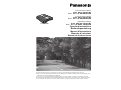 1
1
-
 2
2
-
 3
3
-
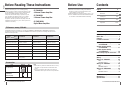 4
4
-
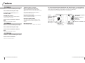 5
5
-
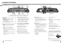 6
6
-
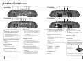 7
7
-
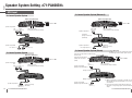 8
8
-
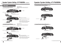 9
9
-
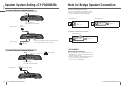 10
10
-
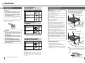 11
11
-
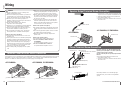 12
12
-
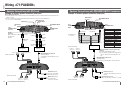 13
13
-
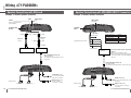 14
14
-
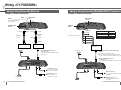 15
15
-
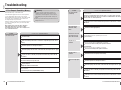 16
16
-
 17
17
-
 18
18
-
 19
19
-
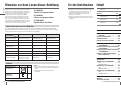 20
20
-
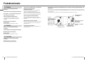 21
21
-
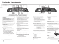 22
22
-
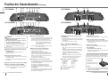 23
23
-
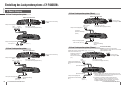 24
24
-
 25
25
-
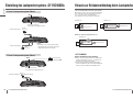 26
26
-
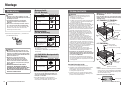 27
27
-
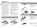 28
28
-
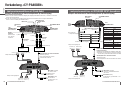 29
29
-
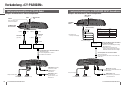 30
30
-
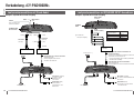 31
31
-
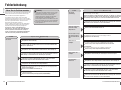 32
32
-
 33
33
-
 34
34
-
 35
35
-
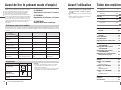 36
36
-
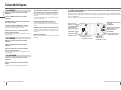 37
37
-
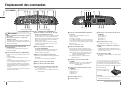 38
38
-
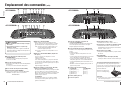 39
39
-
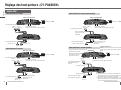 40
40
-
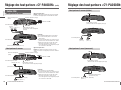 41
41
-
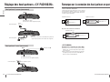 42
42
-
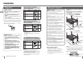 43
43
-
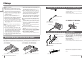 44
44
-
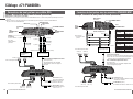 45
45
-
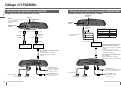 46
46
-
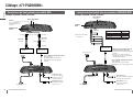 47
47
-
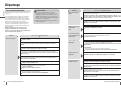 48
48
-
 49
49
-
 50
50
-
 51
51
-
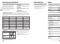 52
52
-
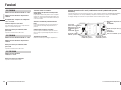 53
53
-
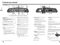 54
54
-
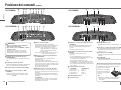 55
55
-
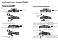 56
56
-
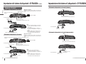 57
57
-
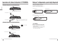 58
58
-
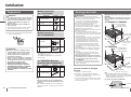 59
59
-
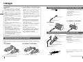 60
60
-
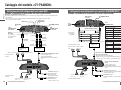 61
61
-
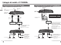 62
62
-
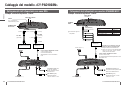 63
63
-
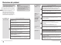 64
64
-
 65
65
-
 66
66
-
 67
67
-
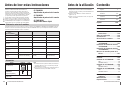 68
68
-
 69
69
-
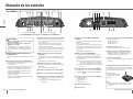 70
70
-
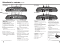 71
71
-
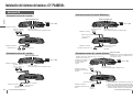 72
72
-
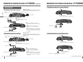 73
73
-
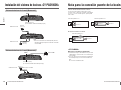 74
74
-
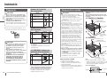 75
75
-
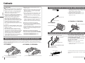 76
76
-
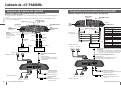 77
77
-
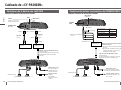 78
78
-
 79
79
-
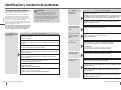 80
80
-
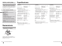 81
81
-
 82
82


Panasonic cy pad 1003 n Bedienungsanleitung
- Kategorie
- Autolautsprecher
- Typ
- Bedienungsanleitung
- Dieses Handbuch eignet sich auch für
in anderen Sprachen
Verwandte Artikel
Andere Dokumente
-
Pioneer GM-D1004 Benutzerhandbuch
-
-
AXTON A470 Bedienungsanleitung
-
-
-
Hifonics TRITON IV Bedienungsanleitung
-
Clarion APA4204 Benutzerhandbuch
-
Hifonics MERCURY IV Bedienungsanleitung
-
Audio Design SX-4120 Bedienungsanleitung
-
Clarion APA4300HX Installationsanleitung