Danfoss Electronic Oil Burner Controls BHO 71A.10 Installationsanleitung
- Typ
- Installationsanleitung

520F0730 DKBD.PI.021.E1.5B 11-2007
057R9872
057R9872
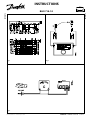
Fig. 1 Fig. 2
Fig. 3
INSTRUCTIONS
BHO 71A.10
Produced by Danfoss A/S © - G1 Advertising 07.11 FO/Bi/E

Oil Burner Control
Type BHO 71A.10
Application
The oil burner control BHO 71A.10 is used for
monitoring and control of 1-stage oil burners
with or without an oil preheater.
According to the existing standards (ISO 3544
and EN 230:2005) the BHO 71A.10 with 10 s
safety time can only be used for burners with r-
ing rates of less than 30 kg oil per hour.
The ame is monitored by a photo unit type LD
or type LDS. The photo unit LD has normal light
sensitivity. The photo unit LDS has increased
light sensitivity.
Classication codes
BHO 71A.10 classied according to EN 230:2005
and EN 267:1991 cl. 5.1.3.2.
Type Classication code
BHO 71A.10 FMCLXN
Compatibility
The BHO 71A.10 is compatible with the BHO 64
in 1-stage applications.
Symbols
Hold relay
When operating with oil preheater, the hold
relay above terminals 3 and 8 will make sure that
the burner stays in operation, if the OTR thermo-
stat brakes.
Note: When operating without preheater, terminal
3 and 8 must be short-circuited.
Base
The base is tted with 12 terminals for the con-
tact plugs of the burner control. Furthermore, it
is tted with:
• 3 extra neutral terminals connected to terminal 2
• 4 interconnected earth terminals, which can
be connected directly to the burner housing
by a plate
• 2 loop terminals marked 31 and 32
• 2 ∅5.4 mm holes for fastening of the base
The base is available with 2 dierent front plates.
One front plate has one knockout on each side
and three identical ones and an oval one on the
front. The other front plate is designed for 5 Pg
11 screwed connections.
Upper part/base
The upper part and the base are kept together
by a spring system. The upper part is released by
pressing a screw driver down into the slot. See
g. 2.
Mounting
The base is mounted with 2 screws through
the ∅5.4 mm holes. The burner control can be
mounted in any position.
Electrical connection
The BHO 71A.10 must be connected as shown
in gure 1.
Note: Remote reset may only be connected to a
push button switch.
Technical data
Rated voltage: 230 V ~
Voltage range: 195-253 V ~
Frequency: 50-60 Hz
Supply fuse max.: 10 A
Enclosure: IP 40
Ambient temperature: –20 to +60°C
Transportation- and
storage temperature: –30 to +70°C
Undervoltage protection: <170 V
Protection class: II
Pollution degree: 2
Terminal loads
Terminal Max. current
3 5 A
4 1 A
5 1 A
6/7 1 A
8 5 A
10 1 A
Note: Total current max. 10 A.
Function
Normal start
When operating with oil preheater, start signal
from the preheater must be given before starting.
After the pre-ignition and prepurge time, the oil
will be released and the ame is ignited.
After the post-ignition time, the burner will be
in normal operation.
Type Code no.
Pre-
purge
t1* t3
Post-
igni-
tion
t3n
Inter-
vals
V1-V2
Safety
time
t2
max.
BHO
71A.10
057H6108 13 15 10
* Prepurge time and pre-ignition time are coincident.
But due to the initialization of the electronics, it will last
up to two seconds before the ignition is switched on.
Safety time
See the table above.
Undervoltage protection
(European standard EN 230:2005)
In the event of under voltage <185 V, the BHO
burner control will prevent the burner from
starting. If undervoltage <170 V occurs during
operation, the BHO burner control will cut o
the oil supply and stop the burner.
In the two undervoltage situations the burner con-
trol reset button will show a ash code (8 ashes).
The burner control will automaticly restart the
burner as described under “normal start”, when
the voltage has again reached 185 V.
Overvoltage
If the mains voltage should reach 264 V, the BHO
burner control will lockout and a ash code can
be read in the reset button, see the paragraphs
Alarm/reset-function and Flash codes.
Max. preheating time
When a BHO burner control has a preheater that
is connected to the mains voltage, it will wait for
a starting signal on terminal 3. If this does not
happen within 10 min., the burner control will
lockout and a ash code can be read in the reset
button, see the paragraphs Alarm/reset-function
and Flash codes.
False light during start up
If the photo unit is exposed to light before the
end of the prepurge time, the burner control will
not release oil and will lockout. A ash code can
be read in the reset button, see the paragraphs
Alarm/reset-function and Flash codes.
No ame formation during start up
If the oil is released and no ame has formed in
the safety time, the burner control will lockout.
A ash code can be read in the reset button, see the
paragraphs Alarm/reset-function and Flash codes.
Flame failure during operation
In the event of ame failure during operation,
the oil supply is cut o after max. 1 sec. and the
burner control restarts the burner as described
under “normal start”. In case of more than 3
ame failures during the same operating period,
the burner control will lockout and a ash code
can be read in the reset button, see the para-
graphs Alarm/reset-function and Flash codes.
Alarm/reset-function
If a fault occurs, the burner control will lockout.
This is shown by a constant red light in the reset
button. To reset the burner control press the but-
ton and keep it down for min. 0.5 sec and max.
3 sec. The burner control will then restart.
Note! If the mains voltage is less than 160 V, the
burner control cannot be reset.
Flash codes
The reason for the burner control lockout can be
read by means of ash codes (see the table below).
Press the button and keep it down for min. 5 sec.
The ash code will be shown as a number of
ashes which will be repeated at intervals of 2 sec.
It is not possible to reset the burner control in this
mode. To stop the ash code, keep the reset button
down again for min. 5 sec. It will then be possible
to reset the burner control.
Flash codes
Event Code
False light 2 ashes
No ame when safety time elapses 3 ashes
More than three restarts in the same
cycle
4 ashes
Max. waiting time on preheater overrun
(10 min)
5 ashes
Supply voltage above 264 V AC 6 ashes
In case of undervoltage, a ash code of 8 ashes
is shown automatically (without changing over
to ash mode).
Flame monitoring
The ame is monitored by a photo unit type LD
or type LDS. These units are compatible with
photo units of the BHO 64 series.
It is, however, always recommended to change
LD/LDS when changing the burner control.
Important! LD/LDS must be connected to terminals
11 and 12.
Note! According to ISO and EN standards, the
burner control will lockout and stop the burner, if
LD/LDS is exposed to light before the end of the
prepurge time.
Max. cable length between BHO 71A.10 and LD/
LDS: 20 m.
Max. permissible ambient temperature for LD/
LDS: -20 to +70ºC.
Control of ame signal g. 3
The photo current must be at least 65 μA at 230 V.
Control of false light signal
With no ame, the photo current must not exceed
5 µA at 230 V.
Time function/explanation
Output signals of control
Required input signals
A'
Initiation of burner with oil preheater OFV
A
Initiation of burner without oil preheater
B
Flame formation
C
Operating position
D
Burner stop
tw
Heating of oil preheater until OTR switches
on
t1
Prepurge
t2
Safety time
t3
Pre-ignition
t3n
Post-ignition
t4
Interval between ame formation and
release of valve V2 (terminal 5)
ENGLISH
Boiler thermostat
High temperature cutout
Ignition unit transformer
Burner motor
Solenoid valve
Photo unit
External alarm
L Phase wire
N Neutral wire
Oil preheater
Oil preheater thermostat
Hold relay

Ölfeuerungsautomat
Typ BHO 71A.10
Anwendung
Ölfeuerungsautomat BHO 71A.10 wird zur
Steuerung und Überwachung von 1- stufigen
Brennern mit oder ohne Ölvorwärmer verwen-
det.
Im Hinblick auf geltende Normen (ISO 3544 und
EN 230:2005) kann BHO 71A.10 (mit 10 sek.
Sicherheitszeit) nur für Brenner mit einer einge-
feuerten Ölmenge bis 30 kg/h verwendet werden.
Die Flammenüberwachung geschieht mit der
Fotozelle LD oder LDS. Die Fotozelle LD hat eine
normale Lichtempndlichkeit. Die Fotozelle LDS
hat eine erhöhte Lichtempndlichkeit.
Klassikation:
Die BHO 70 – Automatenserie wurde gemäß EN
230:2005 und EN 267:1991 Abschn. 5.1.3.2 klassi-
ziert.
Kompatibilität
Die BHO 71A.10 ist kompatibel mit der BHO 64
Serie in 1-stugen Anwendungen.
Symbolerklärung
Halterelais
Im Betrieb mit Ölvorwärmer haben alle Typen
eine Haltefunktion, die während des Betriebs
den OTR kurzschließen (Klemme 3 uns 8).
Achtung: Bei Betrieb ohne Ölvorwärmer müssen die
Klemmen 3 und 8 gebrückt sein.
Unterteil
Das Unterteil ist mit 12 Klemmen für die Stecker
des Automaten versehen. Weiter ist es versehen mit:
• 3 extra Nullklemmen, verbunden mit Klemme 2
• 4 eingegossene und verbundene Erdungsklem-
men, die mit einer Platte direkt mit dem Brenner-
gehäuse verbunden werden können
• 2 Schleifenklemmen, markiert mit 31 und 32
• 2 Stück Löcher 5,4 Ø zur Befestigung des Unterteils
Das Unterteil kann mit 2 verschiedenen Front-
platten geliefert werden. Die eine Frontplatte
hat Ausstoßblenden, je eine seitlich, sowie drei
gleiche und eine ovale auf der Frontseite. Die
andere Frontplatte ist vorgesehen für 5 Stück
PG 11 Verschraubungen.
Oberteil/Unterteil
Das Ober- und Unterteil werden mit einem
Federsystem zusammengehalten. Das Oberteil
wird freigegeben indem ein Schraubenzieher in
den Spalt gesteckt wird, siehe Bild 5.
Montage
Das Unterteil wird mit 2 Schrauben durch die
Löcher 5,4 Ø befestigt.
Der Automat kann in willkürlicher Position
montiert werden.
Elektrische Anschlüsse
BHO 71A.10 wird gemäß Fig. 1 angeschlossen.
Achtung: Die Fernentriegelung darf
nur mit Tasterkontakt angeschlossen werden.
Technische Daten
Nennspanung: 230 V ~
Arbeitsbereich: 195-253 V ~
Frequenz: 50-60 Hz
Netzsicherung max.: 10 A
Schutzart: IP 40
Umgebungstemperatur: –20 bis +60°C
Transport- und Lagerungstemp.: –30 bis +70°C
Unterspannungssicherheit: <170 V
Schutzklasse: II
Dichtheitsklasse: 2
Klemmenbelastung
Achtung: Der Gesamtstrom an Klemme 1 darf 10 A
nicht überschreiten.
Funktion
Normaler Start
Bei Betrieb mit Ölvorwärmer wird das Freigabe-
signal vom Ölvorwärmer abgewartet.
Nach der Vorzündungs- und Vorbelüftungszeit
wird das Öl freigegeben, und die Flamme wird
gebildet. Nach der Nachzündungszeit ist der
Brenner im normalen Betrieb.
Sicherheitszeit
Siehe Obenstehendes Schema
Unterspannungssicherheit
(Europäische Norm EN230:2005)
Unterspannungssichere Automaten sind mit
einer elektronischen Sicherung versehen, die
den Automaten bei Netzstörungen mit Unter-
spannung (<185 V) daran hindern den Brenner
zu starten.
Sollten Unterspannungen <170 V während einer
Betriebsperiode vorkommen, wird der Automat
die Ölzufuhr stoppen und den Brenner abschalten.
In beiden Unterspannungs-Situationen erscheint
automatisch ein Blinksignal mit 8 mal blinken im
Resetknopf
Der Automat startet wieder mit „normalem Start“
wenn die Netzspannung wieder 185 V erreicht.
Überspannung
Wenn die Netzspannung 264 V oder mehr errei-
chen sollte, wird der Automat auf Alarm gehen
und es ist ein Blinkcode im Resetknopf abzulesen
(siehe Abschnitte Alarm-/Resetfunktion und
Blinkcode).
Max. Vorwärmerzeit
Wenn der Automat mit angeschlossenem Vor-
wärmer an Netzspannung gelegt wird, wird ein
Freigabesignal auf Klemme 3 erwartet. Wenn
dies nicht innerhalb von 10 Minuten geschieht
geht der Automat auf Alarm, und es ist ein Blink-
code im Resetknopf abzulesen (siehe Abschnitte
Alarm-/Resetfunktion und Blinkcode).
Fremdlicht bei Start
Wenn der Fotowiderstand im letzten Teil der
Vorbelüftungsphase Licht sieht, wird der Automat
das Öl nicht freigeben und auf Alarm gehen.
Es ist ein Blinkcode im Resetknopf abzulesen
(siehe Abschnitte Alarm-/Resetfunktion und
Blinkcode).).
Keine Flammenbildung im Start
Wenn das Öl freigegeben wurde und innerhalb
der Sicherheitszeit keine Flamme gebildet wird,
wird der Automat auf Alarm gehen. Es ist ein
Blinkcode im Resetknopf abzulesen (siehe Ab-
schnitt „Blinkcode“).
Flammenversagen im Betrieb
Bei Flammenversagen im Betrieb wird die
Ölzufuhr nach max. 1 sek. unterbrochen und
der Automat führt einen „normalen“ Wiederstart
durch. Bei mehr als drei Flammenversagen in
der gleichen Betriebsperiode wird der Automat
auf Alarm gehen und es ist ein Blinkcode im
Resetknopf abzulesen (siehe Abschnitte Alarm-/
Resetfunktion und Blinkcode).
Alarm-/Resetfunktion
Bei Fehlern wird der Automat auf Alarm gehen.
Dieses wird durch konstant rotes Licht im Re-
setknopf angezeigt. Durch drücken des Reset-
knopfes für min. 0,5 bis max. 3 sek. wird der Reset
des Automaten durchgeführt.
Hiernach wird der Automat wieder einen Start
durchführen.
Achtung: Bei Netzspannungen unter 160 V kann
kein Reset des Automaten durchgeführt werden
Blinkcode
Wenn der Automat auf Alarm geht, gibt es die
Möglichkeit die Ursache als Blinkcode abzulesen
(siehe untenstehendes Schema). Dies geschieht,
indem der Resetknopf für min. 5 sek. gedrückt
wird. Danach wird ein Blinkcode gezeigt, der mit
2 sek. Pause wiederholt wird. In diesem Zustand
ist es nicht möglich einen Reset des Automaten
durchzuführen. Um den Zustand der Blinkco-
deanzeige wieder zu verlassen muss der Knopf
wieder für min. 5 sek. gedrückt werden. Danach
ist es möglich den Reset durchzuführen.
Blinkcodes
Ereignis Kode
Falschlicht 2 Blinkcode
Keine Flamme bei Ende von ts 3 Blinkcode
Mehr als drei Wiederstarts
im gleichen Zyklus
4 Blinkcode
Max. Wartezeit vom Vorwärmer
überschritten (10 min.)
5 Blinkcode
Netzspannung über 264 V AC 6 Blinkcode
Bei Unterspannung wird automatisch ein Blink-
code mit 8 Mal blinken angezeigt (ohne Einschalten
des Blinkzustandes).
Flammenüberwachung
Die Flamme wird mit einem Fotowiderstand Typ
LD oder Typ LDS überwacht. Diese sind kompati-
bel mit den Fotowiderständern der BHO 64 Serie.
Es wird aber empfohlen, bei jedem Wechsel
eines Automaten den Fotowiderstand mit aus-
zuwechseln.
Achtung: Es ist wichtig, dass der Fotowiderstand an
den Klemmen 11 und 12 im Unterteil angeschlossen
wird.
Achtung: Im Hinblick auf ISO und EN Normen wird
der BHO Automat abschalten, wenn der Fotowider-
stand im letzten Teil der Vorbelüftungsphase Licht
erkennt.
Max. Kabellänge zwischen BHO 71A.10 und LD/
LDS: 20 m
Max. zul. Umgebungstemperatur für LD/LDS:
-20°C bis 70°C.
Kontrolle des Flammensignals Bild 6
Der Flammenstrom soll für die BHO 70 Serie min.
65µA bei 230 V betragen.
DEUTSCH
Typ Klassikation
BHO 71A.10 FMCLXN
Kesselthermostat
Sicherheitstemperaturbegrenzer
Zündung
Brennermotor
Magnetventil
Fotozelle
Externer Alarm
L Phase
N Null
Ölvorwärmer
Ölvorwärmerthermostat
Halterelais
Klemme Max. Betriebsstrom
3 5 A
4 1 A
5 1 A
6/7 1 A
8 5 A
10 1 A
Typ Bestell. Nr.
Vorbe-
lüftung
t1* t3
Nach-
zün-
dung
t3n
Inter-
vall
V1-V2
Sicher-
heits-
zeit
t2 max.
BHO
71A.10
057H6108 13 15 10
* Vorbelüftungszeit und Vorzündungszeit fallen zusam-
men. Durch die Initialisierung der Elektronik können
aber bis zu 2 Sekunden vergehen bevor die Zündung
eingeschaltet wird.

Kontrolle auf Falschlicht
Ohne Flamme darf der Fotostrom max. 5 µA bei
230 V betragen.
Zeitfunktion/Erklärung
Zeitfunktion/Erklärung
Erforderliche Eingangssignale
A' Start des Brenners mit Ölvorwärmer OFV
A Start des Brenners mit Ölvorwärmer OFV
B Flammenbildung
C Betriebsstellung
D Brennerabschaltung
tw Aufheizen des Ölvorwärmers bis zur
Freigabe über den Kontakt OTR
t1 Vorbelüftung
t2 Sicherheitszeit
t3 Vorzündung
t3n Vorzündung
t4 Intervall zwischen Flammenbildung und
Freigabe der Ventilklemme 5 (V2)
-
 1
1
-
 2
2
-
 3
3
-
 4
4


Danfoss Electronic Oil Burner Controls BHO 71A.10 Installationsanleitung
- Typ
- Installationsanleitung
in anderen Sprachen
Verwandte Artikel
-
Danfoss Oil Burner Controls BHO 70 series Installationsanleitung
-
Danfoss Oil Burner Controls BHO 80 series Installationsanleitung
-
-
-
-
-
