
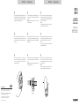
4. Schrauben Sie die montierte Kabelbuchse in die Schiebehülse und drehen
Sie das Gewinde der Schiebehülse
fest. Achten Sie dabei darauf, dass die
Verriegelung der XLR-Buchse nach dem Festdrehen auf einen der beiden
Markierungspfeile der Schiebehülse
gerichtet ist.
Achtung:
Möchten Sie die Schiebehülse
gegen ein späteres Herausdrehen sichern,
bestreichen Sie das Gewinde mit einem Schraubensicherungslack. Danach ist
kein Öffnen des Gewindes mehr möglich!
4. Screw the mounted cable connector
into the sliding sleeve and tighten it.
Make sure that the locking of the XLR socket points to one of the two arrows on
the sliding sleeve
after tightening.
Warning:
If you want to secure the sliding sleeve
against a subsequent unscrewing, apply
a locking paint to the thread. After this the thread cannot be opened anymore!
4. Vissez la prise montée
dans le manchon coulissant et serrez le filetage du
manchon coulissant
. À cet effet, veillez à ce que le verrouillage de la prise
XLR, après le serrage, soit dirigé vers l’une des deux flèches du manchon
coulissant
.
Attention :
Si vous souhaitez empêcher que le manchon coulissant
ne se dévisse
ultérieurement, appliquez sur le filetage un vernis d’arrêt de vis. Un desserrage
du filetage est ensuite impossible !
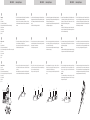
1. Ziehen Sie das Mikrofonkabel durch die Schiebehülse . Das kurze Kabelende
befindet sich auf der Gewindeseite der Schiebehülse
.
Manteln Sie das Kabel vorschriftsmäßig ab. Kabelschirm zur Seite legen,
verdrillen und verzinnen. Die einzelnen Litzen abisolieren, verdrillen und ebenfalls
verzinnen.
1. Pull the microphone cable through the sliding sleeve
. The short end of the
cable is at the threaded end of the sliding sleeve
.
Strip the cable properly. Put the cable shield aside, twist and tin-plate it. Strip
the individual wires, twist and tin-plate them.
1. Faites passer le câble de microphone dans le manchon coulissant
. À cet
effet, l’extrémité de câble courte doit se trouver sur le côté fileté du manchon
coulissant
.
Dénuder dûment le câble avec précaution. Mettre de côté le blindage de câble,
le torsader et l’étamer. Dénuder les différents brins, torsader et également étamer.
2. Löten Sie das Kabel an den Buchseneinsatz
an. Halten Sie dabei die korrekte
Belegung der Kontakte ein. Vermeiden Sie Brücken und Kurzschlüsse. Verbinden
Sie die Schirmung des Kabels zusätzlich mit der Massefahne des Buchsenein-
satzes
.
Schieben Sie die Kabelsicherung
über das Kabel.
2. Solder the cable to the socket insert
. Observe the correct assignment of the
contacts. Avoid bridges and short circuits. Connect the shielding of the cable also
with the ground pin of the socket insert
.
Put the cable protection
over the cable.
2. Soudez le câble sur l’insert de prise
. Observez la bonne affectation des
contacts. Évitez les ponts et courts-circuits. Raccordez de plus le blindage du
câble à la cosse de masse de l’insert de prise
.
Faites glisser le fusible de câble
sur le câble.
GMS 32
•
GMS 52 deutsch
•
english
•
français GMS 32
•
GMS 52 deutsch
•
english
•
français
3. Schieben Sie den Buchseneinsatz mit der Kabelsicherung komplett in das
Buchsengehäuse
ein. Die Führungsnase am Buchseneinsatz muss dabei in
die Führungsnut des Buchsengehäuses
fassen.
Im eingeschobenen Zustand sollte der Buchseneinsatz
mit dem oberen Rand
des Buchsengehäuses
bündig sein.
3. Slide the socket insert
complete with the cable protection into the female
connector housing
. The guide lug on the socket insert must grip into the
groove of the female connector housing
.
In the inserted state of the socket insert
it must meet with the upper edge of
the female connector housing
.
3. Insérez complètement l’insert de prise avec le fusible de câble dans le
boîtier
de prise . L’ergot de guidage sur l’insert de prise doit à cet effet
s’enclencher dans l’encoche du boîtier de prise
.
Une fois inséré, l’insert de prise
doit affleurer le bord supérieur du boîtier de
prise
.
DE
EN
FR
DE
EN
FR
DE
EN
FR
Lieferumfang:
Deckel
Einbaumodul
Schiebehülse (für Einbaumodul)
Buchsengehäuse (Kabeltülle der XLR-Buchse wird nicht benötigt)
Buchseneinsatz
Kabelsicherung
Unterlegscheibe
Mutter
Supplied accessories:
Lid
Installation module
Sliding sleeve (for installation module)
Female connector housing (the cable sleeve of the XLR socket is not required)
Socket insert
Cable protection
Washer
Nut
Contenu de la livraison :
Couvercle
Module encastré
Manchon coulissant (pour module encastré)
Boîtier de prise (passe-câble de la prise XLR n’est pas nécessaire)
Insert de prise
Fusible de câble
Rondelle
Écrou
DE
EN
FR
GMS 32
•
GMS 52 deutsch
•
english
•
français
5. Führen Sie die Schiebehülse von unten in das Einbaumodul ein. Achten Sie
darauf, dass die Entriegelungsnase der Kabelbuchse auf derselben Position ist
wie die Bohrung für die Deckelbefestigung. Die beiden Rastnasen der Schiebe-
hülse
müssen hörbar in den Führungen einrasten. Falls notwendig können Sie
die Schiebehülse
hierfür etwas drehen.
5. Insert the sliding sleeve
from below into the installation module. Make sure
that the release of the cable socket points to the same position as the hole for
the lid fastening. The two clips of the sliding sleeve
must audibly lock into the
slots. If necessary you can slightly turn the sliding sleeve
for this.
5. Insérez le manchon coulissant
par le bas dans le module encastré. Veillez à ce
que l’ergot de déverrouillage de la prise se trouve dans la même position que
l’orifice pour la fixation du couvercle. Les deux ergots d’encliquetage du manchon
coulissant
doivent s’enclencher de façon audible dans les glissières. Au besoin,
vous pouvez légèrement tourner le manchon coulissant
.
DE
EN
FR
DE
EN
FR

8. Montieren Sie den Deckel durch Eindrücken der Kugelbefestigung in die
Bohrung des Einbaumoduls
. Achten Sie darauf, dass Einbaumodul und
Deckel
konzentrisch zueinander ausgerichtet sind. Der Deckel kann durch
Drehen geöffnet oder geschlossen werden.
Achtung:
Um Beschädigungen zu vermeiden, sollten Sie den Deckel
erst nach der
Installation des Einbaumoduls
im Tisch montieren.
8. Attach the lid
by pressing the ball mount into the hole of the installation
module
. Make sure that the installation module and lid are concentrically
aligned with each other. The lid
can be opened or closed by turning.
Caution:
In order to avoid damages, you should attach the lid
after the installation of
the installation module
into the table.
8. Montez le couvercle en pressant la fixation à bille dans l’orifice du module
encastré
. Veillez à ce que le module encastré et le couvercle soient
positionnés concentriquement l’un par rapport à l’autre. Le couvercle
peut être
ouvert ou fermé par rotation.
Attention :
Pour éviter un endommagement, nous vous recommandons de ne monter le
couvercle
qu’après l’installation du module encastré dans la table.
6. Kontrollieren Sie, ob die Kabelbuchse korrekt eingeschoben wurde. Siehe hierfür
Abbildung unten. Bei Bedarf kann die Buchse durch Drücken der seitlichen Rast-
nasen an der Schiebehülse
nochmals herausgeschoben und durch Verdrehen
der Buchse in der Schiebehülse
nachjustiert werden.
6. Check if the cable socket has been inserted correctly. For this refer to the
illustration below. If necessary you can push out the socket once again by pressing
the two clips on the sliding sleeve
and adjust it by turning the socket in the
sliding sleeve
.
6. Vérifiez si la prise a correctement été insérée. Cf. à ce propos l’illustration
ci-dessous. Au besoin, la prise peut, en pressant les deux ergots d’encliquetage
latéraux sur le manchon coulissant
, être retirée et, sur rotation dans le
manchon coulissant
, réajustée.
GMS 32
•
GMS 52 deutsch
•
english
•
français
7. Setzen Sie das Einbaumodul von oben in die Möbelbohrung (ø 49 - 50 mm) ein
und befestigen Sie es an der Unterseite mit der beigelegten Unterlegscheibe
und Mutter .
Wichtig: Die Tischplatte sollte eine Stärke zwischen 11 mm (Minimum) und
55 mm (Maximum) haben.
7. Insert the installation module
from above into the hole of the furniture
(ø 49 - 50 mm) and fix it at the bottom with the supplied washer
and nut .
Important: The table should have a thickness between 11 mm (minimum) and
55 mm (maximum).
7. Placez le module encastré
par le haut dans l’orifice pratiqué dans le meuble
(ø 49 - 50 mm) et fixez-le sur le dessous à l’aide de la rondelle
et de l’écrou
fournis.
Important : le plateau de table doit avoir une épaisseur minimale de 11 mm et
une épaisseur maximale de 55 mm.
GMS 32
•
GMS 52 deutsch
•
english
•
français
DE
EN
FR
DE
EN
FR
DE
EN
FR
11 - 55 mm
GMS 32
GMS 52
EINBAUHALTERUNG
INSTALLATION HOLDER
FIXATION DE MONTAGE
MONTAGEANLEITUNG
INSTALLATION INSTRUCTION
INSTRUCTIONS DE MONTAGE
www.beyerdynamic.com
beyerdynamic GmbH & Co. KG .• Theresienraße 8 •
74072 Heilbronn • Germany • Phone +49 7131 617-300 • info@beyerdynamic.de
Weitere Veriebspaner weltweit finden Sie im Internet unter www.beyerdynamic.com
Abbildungen nicht veragsbindend. Änderungen vorbehalten.
For fuher diributors worldwide, please go to www.beyerdynamic.com
Non-contractual illurations. Subject to change without notice.
DE-EN-FR 2 / GMS 32 - GMS 52 / 654.922 (04.19)
-
 1
1
-
 2
2


Beyerdynamic GMS 52 w Benutzerhandbuch
- Typ
- Benutzerhandbuch
in anderen Sprachen
- English: Beyerdynamic GMS 52 w User manual
- français: Beyerdynamic GMS 52 w Manuel utilisateur