Baumer HOG 10 + DSL Installation and Operating Instructions
- Typ
- Installation and Operating Instructions

HOG 10 + DSL
Kombination
Inkrementaler Drehgeber mit integriertem
programmierbaren, digitalen Drehzahlschalter
Combination
Incremental encoder with integrated
programmable, digital speed switch
Montage- und Betriebsanleitung
Mounting and operating instructions
MB143T1 - 11070464
Baumer_HOG10-DSL-T1_II_DE-EN (20A1)

Baumer_HOG10-DSL-T1_II_DE-EN (20A1)
MB143T1 - 11070464
Inhaltsverzeichnis
Inhaltsverzeichnis
1 Allgemeine Hinweise ..........................................................................................................................................................1
2 Betrieb in explosionsgefährdeten Bereichen
................................................................................................... 3
3 Sicherheitshinweise
........................................................................................................................................................... 5
4 Vorbereitung
............................................................................................................................................................................ 7
4.1 Lieferumfang
............................................................................................................................................................... 7
4.2 Zur Montage erforderlich (nicht im Lieferumfang enthalten)
............................................................. 9
4.3 Zur Demontage erforderlich (nicht im Lieferumfang enthalten)
.....................................................10
4.4 Erforderliches Werkzeug (nicht im Lieferumfang enthalten)
...........................................................10
5 Montage
.....................................................................................................................................................................................11
5.1 Schritt 1
.......................................................................................................................................................................11
5.2 Schritt 2
.......................................................................................................................................................................11
5.3 Schritt 3
.......................................................................................................................................................................12
5.4 Schritt 4
.......................................................................................................................................................................13
5.5 Schritt 5 - Drehmomentstütze
..........................................................................................................................14
5.6 Hinweis zur Vermeidung von Messfehlern
................................................................................................15
5.7 Schritt 6
.......................................................................................................................................................................16
5.8 Montagehinweis
......................................................................................................................................................16
6 Abmessung
.............................................................................................................................................................................17
7 Elektrischer Anschluss
..................................................................................................................................................18
7.1 HOG 10
........................................................................................................................................................................18
7.1.1 Beschreibung der Anschlüsse
.....................................................................................................................18
7.1. 2 Ausgangssignale
.................................................................................................................................................18
7.1.3 Kabelanschluss
....................................................................................................................................................19
7.1.4 Klemmenbelegung
............................................................................................................................................ 22
7.1.5 Sensorkabel HEK 8 (Zubehör)
.................................................................................................................... 22
7.2 DSL.R für den Betrieb mit einem externen Relaismodul DS 93 R (Zubehör)
....................... 23
7.2.1 Kabelanschluss
................................................................................................................................................... 23
7.2.2 Klemmenbelegung
............................................................................................................................................ 25
7.2.3 Blockschaltbild
.................................................................................................................................................... 26
7.2.4 Ausgangsschaltverhalten
.............................................................................................................................. 26
7.2.5 DS 93 R Relaismodul (Zubehör)
................................................................................................................ 27
7.3 DSL.E mit drei internen elektronischen Relais
...................................................................................... 28
7.3.1 Kabelanschluss
................................................................................................................................................... 28
7.3.2 Klemmenbelegung
............................................................................................................................................ 30
7.3.3 Blockschaltbild
.....................................................................................................................................................31
8 Demontage
............................................................................................................................................................................. 32
9 Technische Daten
...............................................................................................................................................................37
9.1 Technische Daten - elektrisch
.........................................................................................................................37
9.2 Technische Daten - elektrisch (Drehgeber)
..............................................................................................37
9.3 Technische Daten - elektrisch (Drehzahlschalter)
................................................................................37
9.4 Technische Daten - mechanisch
................................................................................................................... 38
10 Zubehör
.....................................................................................................................................................................................41
11 EU-Konformitätserklärung
...........................................................................................................................................42

MB143T1 - 11070464
Baumer_HOG10-DSL-T1_II_DE-EN (20A1)
Table of contents
Table of contents
1 General notes .......................................................................................................................................................................... 2
2 Operation in potentially explosive environments
........................................................................................... 4
3 Security indications
............................................................................................................................................................ 6
4 Preparation
............................................................................................................................................................................... 7
4.1 Scope of delivery
...................................................................................................................................................... 7
4.2 Required for mounting (not included in scope of delivery)
................................................................. 9
4.3 Required for dismounting (not included in scope of delivery)
.........................................................10
4.4 Required tools (not included in scope of delivery)
................................................................................10
5 Mounting
...................................................................................................................................................................................11
5.1 Step 1
...........................................................................................................................................................................11
5.2 Step 2
...........................................................................................................................................................................11
5.3 Step 3
...........................................................................................................................................................................12
5.4 Step 4
...........................................................................................................................................................................13
5.5 Step 5 - Torque arm
..............................................................................................................................................14
5.6 How to prevent measurement errors
............................................................................................................15
5.7 Step 6
...........................................................................................................................................................................16
5.8 Mounting instruction
.............................................................................................................................................16
6 Dimension
................................................................................................................................................................................17
7 Electrical connection
.......................................................................................................................................................18
7.1 HOG 10
........................................................................................................................................................................18
7.1.1 Terminalsignicance
........................................................................................................................................18
7.1.2 Output signals
.......................................................................................................................................................18
7.1.3 Cable connection
................................................................................................................................................19
7.1.4 Terminal assignment
........................................................................................................................................ 22
7.1.5 Sensor cable HEK 8 (accessory)
............................................................................................................... 22
7.2 DSL.R suitable for operation with the external relay modul DS 93 R (accessory)
............. 23
7.2.1 Cable connection
............................................................................................................................................... 23
7.2.2 Terminal assignment
........................................................................................................................................ 25
7.2.3 Block diagramm
.................................................................................................................................................. 26
7.2. 4 Switching characteristics
............................................................................................................................... 26
7.2.5 DS 93 R relay modul (accessory)
.............................................................................................................. 27
7.3 DSL.E with three internal electronic relays
.............................................................................................. 28
7.3.1 Cable connection
............................................................................................................................................... 28
7.3.2 Terminal assignment
........................................................................................................................................ 30
7.3.3 Block diagramm
...................................................................................................................................................31
8 Dismounting
.......................................................................................................................................................................... 32
9 Technical data
...................................................................................................................................................................... 39
9.1 Technical data - electrical ratings
................................................................................................................. 39
9.2 Technical data - electrical ratings (encoder)
........................................................................................... 39
9.3 Technical data - electrical ratings (speed switches)
........................................................................... 39
9.4 Technical data - mechanical design
............................................................................................................ 40
10 Accessories
............................................................................................................................................................................41
11 EU Declaration of Conformity
................................................................................................................................... 42

1
Baumer_HOG10-DSL-T1_II_DE-EN (20A1)
MB143T1 - 11070464
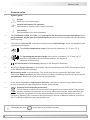
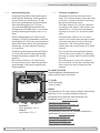
1 Allgemeine Hinweise
1 Allgemeine Hinweise
1.1 Zeichenerklärung:
Gefahr
Warnung bei möglichen Gefahren
Hinweis zur Beachtung
Hinweis zur Gewährleistung eines einwandfreien Betriebes des Gerätes
i
Information
Empfehlung für die Gerätehandhabung
1.2 Die Kombination HOG 10 + DSL ist ein opto-elektronisches Prä zi sionsmessgerät und ein
programmierbares, digital wirkendes Schaltgerät, das mit Sorgfalt nur von technisch quali-
ziertem Per sonal gehandhabt werden darf.
1.3 Die zu erwartende Lebensdauer des Gerätes hängt von den Kugellagern ab, die mit einer
Dauerschmierung ausgestattet sind.
1.4
Der Lagertemperaturbereich des Gerätes liegt zwischen -15 °C bis +70 °C.
1.5
Der Betriebstemperaturbereich des Gerätes liegt zwischen -30 °C bis +85 °C,
eingeschränkt im Ex-Bereich, siehe Abschnitt 2,
am Gehäuse gemessen.
1.6
EU-Konformitätserklärung gemäß den europäischen Richtlinien.
1.7 Wir gewähren 2 Jahre Gewährleistung im Rahmen der Bedingungen des Zentralverbandes der
Elektroindustrie (ZVEI).
1.8 Wartungsarbeiten sind nicht erforderlich. Das Gerät darf nur wie in dieser Anleitung beschrie-
ben geöffnet werden. Reparaturen, die ein vollständiges Öffnen des Gerätes erfordern, sind
ausschließlich vom Hersteller durchzuführen. Am Gerät dürfen keine Veränderungen vorge-
nommen werden.
1.9 Bei Rückfragen bzw. Nachlieferungen sind die auf dem Typenschild des Gerätes angege-
benen Daten, insbesondere Typ und Seriennummer, unbedingt anzugeben.
1.10
Entsorgung (Umweltschutz):
Gebrauchte Elektro- und Elektronikgeräte dürfen nicht im Hausmüll entsorgt werden.
Das Produkt enthält wertvolle Rohstoffe, die recycelt werden können. Wenn immer
möglich sollen Altgeräte lokal am entsprechenden Sammeldepot entsorgt werden. Im
Bedarfsfall gibt Baumer den Kunden die Möglichkeit, Baumer-Produkte fachgerecht zu entsor-
gen. Weitere Informationen siehe www.baumer.com.
i
Achtung!
Beschädigung des auf dem Gerät bendlichen Siegels führt zu Gewährleistungsver-
lust.

MB143T1 - 11070464
Baumer_HOG10-DSL-T1_II_DE-EN (20A1)
2
General notes 1
1 General notes
1.1 Symbol guide:
Danger
Warnings of possible danger
General information for attention
Informations to ensure correct device operation
i
Information
Recommendation for device handling
1.2 The combination HOG 10 + DSL is an opto electro nic precision measurement device and a
programmable, digital operated switching device which must be handled with care by skilled
personnel only.
1.3 The expected service life of the device depends on the ball bearings, which are equipped with
a permanent lubrication.
1.4
The storage temperature range of the device is between -15 °C and +70 °C.
1.5
The operating temperature range of the device is between -30 °C and +85 °C,
restricted in potentially explosive environments, see section 2,
measured at the housing.
1.6
EU Declaration of Conformity meeting to the European Directives.
1.7 We grant a 2-year warranty in accordance with the regulations of the ZVEI (Central Association
of the German Electrical Industry).
1.8 Maintenance work is not necessary. The device may be only opened as described in this
instruction. Repair work that requires opening the device completely must be carried out by the
manufacturer. Alterations of the device are not permitted.
1.9 In the event of queries or subsequent deliveries, the data on the device type label must be
quoted, especially the type designation and the serial number.
1.10
Disposal (environmental protection):
Do not dispose of electrical and electronic equipment in household waste. The product
contains valuable raw materials for recycling. Whenever possible, waste electrical and
electronic equipment should be disposed locally at the authorized collection point. If
necessary, Baumer gives customers the opportunity to dispose of Baumer products profession-
ally. For further information see www.baumer.com.
i
Warning!
Damaging the seal on the device invalidates warranty.

3
Baumer_HOG10-DSL-T1_II_DE-EN (20A1)
MB143T1 - 11070464
2 Betrieb in explosionsgefährdeten Bereichen
2 Betrieb in explosionsgefährdeten Bereichen
Das Gerät entspricht der Richtlinie 2014/34/EU für explosionsgefährdete Bereiche.
Der Einsatz ist gemäß den Gerätekategorien 3 G (Ex-Atmosphäre Gas) und 3 D (Ex-Atmo-
sphäre Staub) zulässig.
Das Relaismodul DS 93 R (als Zubehör erhältlich, siehe Abschnitt 7.2.5) darf nicht in explosions-
gefährdeten Bereichen eingesetzt werden.
Gerätekategorie 3 G: - Ex-Kennzeichnung: II 3 G Ex nA IIC T4 Gc
- Normenkonformität: EN 60079-0:2012 + A11:2013
EN 60079-15:2010
- Zündschutzart: nA
- Temperaturklasse: T4
- Gerätegruppe: II
Gerätekategorie 3 D: - Ex-Kennzeichnung: II 3 D Ex tc IIIC T135°C Dc
- Normenkonformität: EN 60079-31:2014
- Schutzprinzip: Schutz durch Gehäuse
- Max. Oberächentemperatur: +135 °C
- Gerätegruppe: III
Der Einsatz in anderen explosionsgefährdeten Bereichen ist nicht zulässig.
2.1 Der maximale Umgebungstemperaturbereich für den Einsatz des Gerätes im Ex-Bereich
beträgt -20 °C bis +40 °C.
2.2 Der Anlagenbetreiber hat zu gewährleisten, dass eine mögliche Staubablagerung eine maxi-
male Schichtdicke von 5 mm nicht überschreitet (gemäß EN 60079-14).
2.3 Eine gegebenenfalls an anderen Stellen aufgeführte UL-Listung gilt nicht für den Einsatz im
Ex-Bereich.
2.4 Das Gerät darf nur in Betrieb genommen werden, wenn ...
– die Angaben auf dem Typenschild des Gerätes mit dem zulässigen Ex-Einsatzbereich vor
Ort übereinstimmen (Gerätegruppe, Kategorie, Zone, Temperaturklasse bzw. maximale
Oberächentemperatur),
– die Angaben auf dem Typenschild des Gerätes mit dem Spannungsnetz übereinstimmen,
– das Gerät unbeschädigt ist (keine Schäden durch Transport und Lagerung) und
– sichergestellt ist, dass keine explosionsfähige Atmosphäre, Öle, Säure, Gase, Dämpfe,
Strahlungen etc. bei der Montage vorhanden sind.
2.5 An Betriebsmitteln, die in explosionsgefährdeten Bereichen eingesetzt werden, darf keine
Veränderung vorgenommen werden. Reparaturen dürfen nur durch vom Hersteller autorisierte
Stellen ausgeführt werden. Bei Zuwiderhandlung erlischt die Ex-Zulassung.
2.6 Bei der Montage und Inbetriebnahme ist die Norm EN 60079-14 zu beachten.
Das Gerät ist entsprechend den Angaben in der Montage- und Betriebsanleitung zu
betreiben. Die für die Verwendung bzw. den geplanten Einsatzzweck zutreffenden
Gesetze, Richtlinien und Normen sind zu beachten.

MB143T1 - 11070464
Baumer_HOG10-DSL-T1_II_DE-EN (20A1)
4
Operation in potentially explosive environments 2
2 Operation in potentially explosive environments
The device complies with the directive 2014/34/EU for potentionally explosive atmospheres.
It can be used in accordance with equipment categories 3 G (explosive gas atmosphere) and
3 D (explosive dust atmosphere).
The relais module DS 93 R (available as accessory, see section 7.2.5) must not be used in
potentionally explosive atmospheres.
Equipment category 3 G: - Ex labeling: II 3 G Ex nA IIC T4 Gc
- Conforms to standard: EN 60079-0:2012 + A11:2013
EN 60079-15:2010
- Type of protection: nA
- Temperature class: T4
- Group of equipment: II
Equipment category 3 D: - Ex labeling: II 3 D Ex tc IIIC T135°C Dc
- Conforms to standard: EN 60079-31:2014
- Protective principle: Protection by enclosure
- Max. surface temperature: +135 °C
- Group of equipment: III
The operation in other explosive atmospheres is not permissible.
2.1 In Ex areas the device must only be used within the ambient temperature range from -20 °C to
+40 °C.
2.2 The plant operator must ensure that any possible dust deposit does not exceed a thickness of
5 mm (in accordance with EN 60079-14).
2.3 An UL listing that may be stated elsewhere is not valid for use in explosive environments.
2.4 Operation of the device is only permissible when ...
– the details on the type label of the device match the on-site conditions for the permissible
Ex area in use (group of equipment, equipment category, zone, temperature class or maxi-
mum surface temperature),
– the details on the type label of the device match the electrical supply network,
– the device is undamaged (no damage resulting from transport or storage), and
– it has been checked that there is no explosive atmosphere, oils, acids, gases, vapors,
radiation etc. present when mounting.
2.5 It is not permissible to make any alteration to equipment that is used in potentially explosive en-
vironments. Repairs may only be carried out by authorized authorities provided by the manufac-
turer. Contravention invalidates the EX approval.
2.6 Attend the norm EN 60079-14 during mount and operation.
The device must be operated in accordance with the stipulations of the mounting and
operating instructions. The relevant laws, regulations and standards for the planned
application must be observed.

5
Baumer_HOG10-DSL-T1_II_DE-EN (20A1)
MB143T1 - 11070464
3 Sicherheitshinweise
3 Sicherheitshinweise
3.1 Verletzungsgefahr durch rotierende Wellen
Haare und Kleidungsstücke können von rotierenden Wellen erfasst werden.
• Vor allen Arbeiten alle Betriebsspannungen ausschalten und Maschinen stillsetzen.
3.2 Zerstörungsgefahr durch elektrostatische Auadung
Die elektronischen Bauteile im Gerät sind empndlich gegen hohe Spannungen.
• Steckkontakte und elektronische Komponenten nicht berühren.
• Ausgangsklemmen vor Fremdspannungen schützen.
• Maximale Betriebsspannung nicht überschreiten.
3.3 Zerstörungsgefahr durch mechanische Überlastung
Eine starre Befestigung kann zu Überlastung durch Zwangskräfte führen.
• Die Beweglichkeit des Gerätes niemals einschränken.
Unbedingt die Montagehinweise beachten.
• Die vorgegebenen Abstände und/oder Winkel unbedingt einhalten.
3.4 Zerstörungsgefahr durch mechanischen Schock
Starke Erschütterungen, z. B. Hammerschläge, können zur Zerstörung der Abtastung führen.
• Niemals Gewalt anwenden.
Bei sachgemäßer Montage lässt sich alles leichtgängig zusammenfügen.
• Für die Demontage geeignetes Abziehwerkzeug benutzen.
3.5 Zerstörungsgefahr durch Verschmutzung
Schmutz kann im Gerät zu Kurzschlüssen und zur Beschädigung der Abtastung führen.
• Während aller Arbeiten am Gerät auf absolute Sauberkeit achten.
• Niemals Öl oder Fett in das Innere des Gerätes gelangen lassen.
3.6 Zerstörungsgefahr durch klebende Flüssigkeiten
Klebende Flüssigkeiten können die Abtastung und die Kugellager beschädigen. Die Demontage
eines mit der Achse verklebten Gerätes kann zu dessen Zerstörung führen.
3.7 Explosionsgefahr
Das Gerät darf in explosiongefährdeten Bereichen der Kategorien 3 D und 3 G eingesetzt wer-
den. Der Betrieb in anderen explosionsgefährdeten Bereichen ist nicht zulässig.

MB143T1 - 11070464
Baumer_HOG10-DSL-T1_II_DE-EN (20A1)
6
Security indications 3
3 Security indications
3.1 Risk of injury due to rotating shafts
Hair and clothes may become tangled in rotating shafts.
• Before all work switch off all voltage supplies and ensure machinery is stationary.
3.2 Risk of destruction due to electrostatic charge
Electronic parts contained in the device are sensitive to high voltages.
• Do not touch plug contacts or electronic components.
• Protect output terminals against external voltages.
• Do not exceed maximum voltage supply.
3.3 Risk of destruction due to mechanical overload
Rigid mounting may give rise to constraining forces.
• Never restrict the freedom of movement of the device.
The mounting instructions must be followed.
• Itisessentialthatthespeciedclearancesand/oranglesareobserved.
3.4 Risk of destruction due to mechanical shock
Violent shocks, e. g. due to hammer impacts, can lead to the destruction of the sensing system.
• Never use force.
Mounting is simple when correct procedure is followed.
• Use suitable puller for dismounting.
3.5 Risk of destruction due to contamination
Dirt penetrating inside the device can cause short circuits and damage the sensing system.
• Absolute cleanliness must be maintained when carrying out any work on the device.
• Never allow lubricants to penetrate the device.
3.6 Risk of destruction due to adhesive uids
Adhesiveuidscandamagethesensingsystemandtheballbearings.Dismountingadevice,
secured to a shaft by adhesive may lead to the destruction of the device.
3.7 Explosion risk
You can use the device in areas with explosive atmospheres of category 3 D and 3 G. The op-
eration in other explosive atmospheres is not permissible.

7
Baumer_HOG10-DSL-T1_II_DE-EN (20A1)
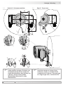
MB143T1 - 11070464
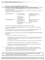
1
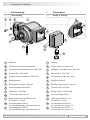
Gehäuse
2
Stützblech für Drehmomentstütze
3
Sechskantschraube M6x18 mm, ISO 4017
4
Scheibe B6,4, ISO 7090
5
Selbstsichernde Mutter M6, ISO 10511
6
Spannelement
7
Erdungsband, Länge ~230 mm
8
Klemmenkastendeckel DSL
9
Federring 4, DIN 7980
10
Torxschraube M4x25 mm
11
Kabelverschraubung M20x1,5 mm
für Kabel ø5...13 mm
12a
Anschlussplatine DSL.R
(je nach Bestellung), siehe Abschnitt 7.2.
12b
Anschlussplatine DSL.E
(je nach Bestellung), siehe Abschnitt 7.3.
1
Housing
2
Support plate for torque arm
3
Hexagon screw M6x18 mm, ISO 4017
4
Washer B6.4, ISO 7090
5
Self-locking nut M6, ISO 10511
6
Clamping element
7
Earthing strap, length ~230 mm
8
Terminal box cover DSL
9
Spring washer 4, DIN 7980
10
Torx screw M4x25 mm
11
Cable gland M20x1.5 mm
for cable ø5...13 mm
12a
Connecting board DSL.R
(as ordered), see section 7.2.
12b
Connecting board DSL.E
(as ordered), see section 7.3.
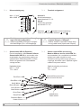
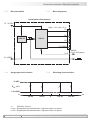
4 Vorbereitung
4.1 Lieferumfang
4 Preparation
4.1 Scope of delivery
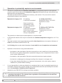
4 Vorbereitung/Preparation
1
2
6
3 4 5
7
8
9
10
11
12a
12b

MB143T1 - 11070464
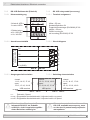
Baumer_HOG10-DSL-T1_II_DE-EN (20A1)
8
Vorbereitung/Preparation 4
4.1 Lieferumfang 4.1 Scope of delivery
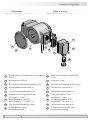
13
Einseitig offene Hohlwelle mit Schlüsseläche
SW 17
14
Abdeckung mit O-Ring
15
Ejot-Innensechskantschraube M4x14 mm
16
Klemmenkastendeckel HOG 10
17
Torx-/Schlitzschraube M4x32 mm
18
Kabelverschraubung M20x1,5 mm
für Kabel ø5...13 mm
19
Anschlussplatine HOG 10,
siehe Abschnitt 7.1.3.3 und 7.1.4.
20
Torx-/Schlitzschraube M3x10 mm
21
D-SUB Stecker 9-polig
am Gerätegehäuse
13
Blindhollowshaftwithspannerat
17a/f
14
Cover with o-ring
15
Ejot hexagon socket screw M4x14 mm
16
Terminal box cover HOG 10
17
Torx/slottedscrewM4x32mm
18
Cable gland M20x1.5 mm
for cable ø5...13 mm
19
Connecting board HOG 10,
see section 7.1.3.3 and 7.1.4.
20
Torx/slottedscrewM3x10mm
21
D-SUB connector (male) 9-pin
on the device housing
13
14
15
16
17
18
19
20
21

9
Baumer_HOG10-DSL-T1_II_DE-EN (20A1)
MB143T1 - 11070464
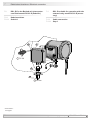
4 Vorbereitung/Preparation
4.2 Zur Montage erforderlich
(nicht im Lieferumfang enthalten)
4.2 Required for mounting
(not included in scope of delivery)
22
25a
25e
25d
25b
25c
26a
26b
23 24
3x
3x
25
26
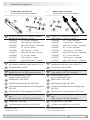
22
Drehmomentstütze, als Zubehör erhältlich:
Bestellnummer Länge L, Version
11043628 67...70 mm, Standard
11004078 125 (±5) mm
1)
, Standard
11002915 440 (+20/-15) mm
2)
, Standard
11054917 67...70 mm, isoliert
11072795 125 (±5) mm
1)
, isoliert
11082677 440 (+20/-15) mm
2)
, isoliert
11054918 67...70 mm, rostfrei
11072787 125 (±5) mm
1)
, rostfrei
11072737 440 (+20/-15) mm
2)
, rostfrei
23
Sensorkabel HEK 8,
als Zubehör erhältlich, siehe Abschnitt 7.1.5.
24
Anschlusskabel für DSL
25
Montageset als Zubehör erhältlich:
Bestellnummer 11077197, bestehend aus ...
25a
Gewindestange M6 (1.4104),
Länge variabel (≤210 mm)
25b
Scheibe B6,4, ISO 7090
25c
Selbstsichernde Mutter M6, ISO 10511
25d
Zylinderschraube M6x8 mm für Erdungsband,
ISO 1207
25e
Scheibe B6,4 für Erdungsband, ISO 7090
26
Montage-/Demontageset als Zubehör erhält-
lich:
Bestellnummer 11077087, bestehend aus ...
26a
Federring 6, DIN 7980
26b
Zylinderschraube M6x30 mm, ISO 4762
1)
Kürzbar auf ≥71 mm
2)
Kürzbar auf ≥131 mm
22
Torque arm, available as accessory:
Order number Length L, version
11043628 67...70 mm, standard
11004078 125 (±5) mm
1)
, standard
11002915 440(+20/-15)mm
2)
, standard
11054917 67...70 mm, insulated
11072795 125 (±5) mm
1)
, insulated
11082677 440(+20/-15)mm
2)
, insulated
11054918 67...70 mm, stainless
11072787 125 (±5) mm
1)
, stainless
11072737 440(+20/-15)mm
2)
, stainless
23
Sensor cable HEK 8,
available as accessory, see section 7.1.5.
24
Connecting cable for DSL
25
Mounting kit available as accessory:
Order number 11077197, including ...
25a
Thread rod M6 (1.4104),
lengthvariable(≤210mm)
25b
Washer B6.4, ISO 7090
25c
Self-locking nut M6, ISO 10511
25d
Cylinder screw M6x8 mm for earthing strap,
ISO 1207
25e
Washer B6.4 for earthing strap, ISO 7090
26
Mounting/dismountingkitavailableasacces-
sory:
Order number 11077087, including ...
26a
Spring washer 6, DIN 7980
26b
Cylinder screw M6x30 mm, ISO 4762
1)
Canbeshortenedto≥71mm
2)
Canbeshortenedto≥131mm
L

MB143T1 - 11070464
Baumer_HOG10-DSL-T1_II_DE-EN (20A1)
10
Vorbereitung/Preparation 4
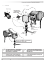
4.3 Zur Demontage erforderlich
(nicht im Lieferumfang enthalten)
4.3 Required for dismounting
(not included in scope of delivery)
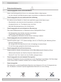
4.4 Erforderliches Werkzeug
(nicht im Lieferumfang enthalten)
4.4 Required tools
(not included in scope of delivery)
26
26c 26d
26
Montage-/Demontageset als Zubehör erhält-
lich:
Bestellnummer 11077087, bestehend aus ...
26c
Gewindestift M6x10 mm, ISO 7436
26d
Zylinderschraube M8x45 mm, ISO 4762
26
Mounting/dismountingkitavailableasacces-
sory:
Order number 11077087, including ...
26c
Setscrew M6x10 mm, ISO 7436
26d
Cylinder screw M8x45 mm, ISO 4762
3, 5 und 6 mm
1,6x8 mm und 0,8x4 mm
10 (2x), 17 und 22 mm
TX 10, TX 20
27
Werkzeugset als Zubehör erhältlich,
Bestellnummer: 11068265
3, 5 and 6 mm
1.6x8 mm and 0.8x4 mm
10 (2x), 17 and 22 mm
TX 10, TX 20
27
Tool kit available as accessory,
order number: 11068265

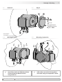
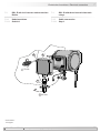
5 Montage / Mounting
11
Baumer_HOG10-DSL-T1_II_DE-EN (20A1)
MB143T1 - 11070464
5.2 Schritt 2 5.2 Step 2
5 Montage
5.1 Schritt 1
5 Mounting
5.1 Step 1
22
*
*
* *
14
15
*
*
* Siehe Seite 7, 8 oder 9
See page 7, 8 or 9
3
5 4
10 mm
10 mm
3 mm

Montage / Mounting 5
MB143T1 - 11070464
Baumer_HOG10-DSL-T1_II_DE-EN (20A1)
12
5.3 Schritt 3 5.3 Step 3
Antriebswelle einfetten. Lubricate drive shaft.
Die Antriebswelle sollte einen
möglichst kleinen Rundlauffehler
aufweisen, da dieser zu einem
Winkelfehler führen kann, siehe
Abschnitt 5.6.
Rundlauffehler verursachen Vibrati-
onen, die die Lebensdauer des
Gerätes verkürzen können.
The drive shaft should have as less
runout as possible because this can
otherwise result in an angle error, see
section 5.6.
Runouts can cause vibrations, which
can shorten the service life of the
device.
52 mm (40...52 mm)
ø16
h6
mm
Zentrierbohrung
Center hole
DIN 332-D, M6x16 mm
6
*
M6
≥ ø20 mm
ø16
h6
mm
52 mm
(40...52 mm)
53 mm
16 mm
6
13
*
*
* Siehe Seite 7 oder 8
See page 7 or 8

5 Montage / Mounting
13
Baumer_HOG10-DSL-T1_II_DE-EN (20A1)
MB143T1 - 11070464
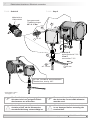
5.4 Schritt 4 5.4 Step 4
Anzugsmoment:
Tightening torque:
M
t
= 6 Nm
26b26a
25a
22
25b 25b
22
21b
25c25b
25d
25d
**
*
*
* * **
**
*
*
* Siehe Seite 9
See page 9
25c
*
17 mm
10 mm
5 mm
1.6x8 mm

Montage / Mounting 5
MB143T1 - 11070464
Baumer_HOG10-DSL-T1_II_DE-EN (20A1)
14
5.5 Schritt 5 - Drehmomentstütze 5.5 Step 5 - Torque arm
15°
15°
9°
9°
9°
9°
L1
L2 (≥L1)
Die Montage der Drehmomentstütze
sollte spielfrei erfolgen. Ein Spiel von
beispielsweise ±0,03 mm entspricht
einem Rundlauffehler des Gerätes von
0,06 mm, was zu einem großen
Winkelfehler führen kann, siehe
Abschnitt 5.6.
The torque arm should be mounted
free from clearance. A play of just
±0.03 mm, results in a runout of the
combination of 0.06 mm. That may lead
to a large angle error, see section 5.6.

5 Montage / Mounting
15
Baumer_HOG10-DSL-T1_II_DE-EN (20A1)
MB143T1 - 11070464
5.6 Hinweis zur Vermeidung von Messfeh-
lern
Für einen einwandfreien Betrieb des
Gerätes ist eine korrekte Montage, ins-
besondere auch der Drehmomentstütze,
notwendig, wie beschrieben in Abschnitt
5.1 bis 5.5.
Der Rundlauffehler der Antriebswelle
sollte möglichst nicht mehr als 0,2 mm
(0,03 mm empfohlen) betragen, da hier-
durch Winkelfehler verursacht werden.
Solche Winkelfehler können durch einen
größeren Abstand L1 reduziert werden
3)
.
Dabei ist zu beachten, dass die Länge L2
der Drehmomentstütze, siehe Abschnitt
5.5, mindestens gleich L1 sein sollte
4)
.
Der Winkelfehler kann wie folgt berechnet
werden:
Δρ
mech
= ± 90°/π · R/L1
mit R:
Rundlauffehler in mm
L1:
Abstand der Drehmomentstütze zum
Gerätemittelpunkt in mm
Berechnungsbeispiel:
Für R = 0,06 mm und L1 = 69,5 mm ergibt
sich ein Winkelfehler
Δρ
mech
von ± 0,025°.
i
Weitere Informationen erhalten Sie
unter der Telefon-Hotline
+49 (0)30 69003-111
5.6 How to prevent measurement errors
To ensure that the device operates cor-
rectly, it is necessary to mount it accu-
rately as described in section 5.1 to 5.5,
which includes correct mounting of the
torque arm.
The radial runout of the drive shaft should
not exceed 0.2 mm (0.03 mm
recommended), if at all possible, to pre-
vent an angle error.
An angle error may be reduced by
increasing the length of L1
3)
. Make sure
that the length L2 of the torque arm, see
section 5.5, is at least equal to L1
4)
.
The angle error can be calculated as
follows:
Δρ
mech
=±90°/π · R/L1
with R:
Radial runout in mm
L1:
Distance of the torque arm to the center
point of the device in mm
Example of calculation:
For R = 0.06 mm and L1 = 69.5 mm the
resulting angle error
Δρ
mech
equals ± 0.025°.
i
For more information,
call the telephone hotline at
+49 (0)30 69003-111
3)
Auf Anfrage sind hierzu verschiedene Stützbleche für die
Drehmomentstütze erhältlich.
4)
Wenn L2 < L1 muss mit der Länge L2 gerechnet werden.
3)
For this different braces for the torque arm are
available on request.
4)
If L2 < L1, L2 must be used in the calculation formula.

Montage / Mounting 5
MB143T1 - 11070464
Baumer_HOG10-DSL-T1_II_DE-EN (20A1)
16
5.7 Schritt 6 5.7 Step 6
5.8 Montagehinweis 5.8 Mounting instruction
15 14
* *
* Siehe Seite 8
See page 8
Anzugsmoment
Tightening torque
M
t
= 2...3 Nm
i
Wir empfehlen, das Gerät so zu
montieren, dass der Kabelanschluss
keinem direkten Wassereintritt
ausgesetzt ist.
i
It is recommended to mount the device
with cable connection facing down-
ward and being not exposed to water.
3 mm

17
Baumer_HOG10-DSL-T1_II_DE-EN (20A1)
MB143T1 - 11070464
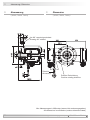
6 Abmessung/Dimension
6 Abmessung
(74069, 74650, 74661)
6 Dimension
(7406 9, 74650, 74661)
Positive Drehrichtung
Positive rotating direction
Zubehör
Accessory
Um 90° versetzt gezeichnet
Drawing 90° rotated
Alle Abmessungen in Millimeter (wenn nicht anders angegeben)
All dimensions in millimeters (unless otherwise stated)
Seite wird geladen ...
Seite wird geladen ...
Seite wird geladen ...
Seite wird geladen ...
Seite wird geladen ...
Seite wird geladen ...
Seite wird geladen ...
Seite wird geladen ...
Seite wird geladen ...
Seite wird geladen ...
Seite wird geladen ...
Seite wird geladen ...
Seite wird geladen ...
Seite wird geladen ...
Seite wird geladen ...
Seite wird geladen ...
Seite wird geladen ...
Seite wird geladen ...
Seite wird geladen ...
Seite wird geladen ...
Seite wird geladen ...
Seite wird geladen ...
Seite wird geladen ...
Seite wird geladen ...
Seite wird geladen ...
Seite wird geladen ...
Seite wird geladen ...
Seite wird geladen ...
-
 1
1
-
 2
2
-
 3
3
-
 4
4
-
 5
5
-
 6
6
-
 7
7
-
 8
8
-
 9
9
-
 10
10
-
 11
11
-
 12
12
-
 13
13
-
 14
14
-
 15
15
-
 16
16
-
 17
17
-
 18
18
-
 19
19
-
 20
20
-
 21
21
-
 22
22
-
 23
23
-
 24
24
-
 25
25
-
 26
26
-
 27
27
-
 28
28
-
 29
29
-
 30
30
-
 31
31
-
 32
32
-
 33
33
-
 34
34
-
 35
35
-
 36
36
-
 37
37
-
 38
38
-
 39
39
-
 40
40
-
 41
41
-
 42
42
-
 43
43
-
 44
44
-
 45
45
-
 46
46
-
 47
47
-
 48
48


Baumer HOG 10 + DSL Installation and Operating Instructions
- Typ
- Installation and Operating Instructions
in anderen Sprachen
- English: Baumer HOG 10 + DSL
Verwandte Artikel
-
Baumer HOG 165 + DSL Installation and Operating Instructions
-
-
-
-
-
-
-
-
-