
Dell EMC DCPMM
Benutzerhandbuch
February 2020
Rev. A04

Hinweise, Vorsichtshinweise und Warnungen
ANMERKUNG: Eine ANMERKUNG macht auf wichtige Informationen aufmerksam, mit denen Sie Ihr Produkt besser
einsetzen können.
VORSICHT: Ein VORSICHTSHINWEIS warnt vor möglichen Beschädigungen der Hardware oder vor Datenverlust und
zeigt, wie diese vermieden werden können.
WARNUNG: Mit WARNUNG wird auf eine potenziell gefährliche Situation hingewiesen, die zu Sachschäden,
Verletzungen oder zum Tod führen kann.
© 2017–2020 Dell Inc. oder ihre Tochtergesellschaften. Alle Rechte vorbehalten. Dell, EMC und andere Marken sind Marken von Dell Inc. oder
entsprechenden Tochtergesellschaften. Andere Marken können Marken ihrer jeweiligen Inhaber sein.

Kapitel 1: Einführung.......................................................................................................................5
Systemanforderungen...........................................................................................................................................................5
Terminologie........................................................................................................................................................................... 6
Kapitel 2: Änderungsliste.................................................................................................................8
Kapitel 3: Hardware.........................................................................................................................9
Server-Hardware-Konfiguration..........................................................................................................................................9
DIMM-Installation und -Entfernung.................................................................................................................................... 9
DCPMM-Hardware-Konfiguration...................................................................................................................................... 9
DCPMM – Empfohlene Topologien.............................................................................................................................. 9
CPU-Typ und Beschränkungen für die maximale Speicherkapazität...................................................................... 17
DCPMM-Kombinierungs- und Bestückungsregeln.................................................................................................... 17
Kapitel 4: BIOS..............................................................................................................................18
BIOS-Konfigurationseinstellung für Intel DCPMM...........................................................................................................18
DIMM-Erkennung...........................................................................................................................................................18
App-Direct-Modus-Konfiguration...................................................................................................................................... 19
Ziel erstellen.................................................................................................................................................................... 19
Regionsinformationen................................................................................................................................................... 20
Speichermoduskonfiguration............................................................................................................................................. 22
Ziel erstellen....................................................................................................................................................................22
Kapitel 5: DCPMM-Ereignisberichte............................................................................................... 23
Ereignisse während der Laufzeit....................................................................................................................................... 23
Ereignisse während des Startvorgangs............................................................................................................................ 23
Kapitel 6: Intel DCPMM-Verwaltung mit iDRAC................................................................................27
iDRAC-GUI............................................................................................................................................................................27
DCPMM-Firmware-Version..........................................................................................................................................27
DCPMM-Hardware-Status.......................................................................................................................................... 27
DCPMM-Zielkonfiguration über die iDRAC-GUI........................................................................................................28
DCPMM – Geschätzte verbleibende Schreibdauer..................................................................................................29
Kapitel 7: DCPMM-Sicherheit........................................................................................................ 30
Speichermodus.................................................................................................................................................................... 30
App-Direct............................................................................................................................................................................30
Kryptografisches Löschen und DCPMM-Sanitize........................................................................................................... 31
Kryptografisches Löschen............................................................................................................................................32
Sanitize............................................................................................................................................................................32
Kapitel 8: DIMM-Konfigurationsänderungen.................................................................................... 34
Inhaltsverzeichnis
Inhaltsverzeichnis 3

Kapitel 9: Windows........................................................................................................................35
PMEM im App-Direct-Modus............................................................................................................................................35
Verwaltung von PMEM-Laufwerken.......................................................................................................................... 36
Physische PMEM-Laufwerke auflisten und ihren Funktionszustand überprüfen................................................. 37
PMEM-Laufwerke erstellen..........................................................................................................................................37
PMEM-Laufwerke entfernen.......................................................................................................................................38
PMEM-Laufwerk mit Interleave-Sätzen.......................................................................................................................... 38
PMEM-Laufwerkserstellung mit Interleave-Sätzen..................................................................................................38
PMEM im Speichermodus..................................................................................................................................................39
Fehlerbehebung und Ereignisüberwachung unter Windows......................................................................................... 39
Kapitel 10: Linux............................................................................................................................ 41
Persistente Speichergeräte identifizieren und erkennen................................................................................................ 41
DCPMM-Geräte auflisten............................................................................................................................................. 41
Namespaces erstellen....................................................................................................................................................41
Dateisysteme auf einem Namespace-Gerät mounten...............................................................................................41
Namespaces löschen.....................................................................................................................................................42
Verwaltungsdienstprogramm.............................................................................................................................................42
DCPMM-Funktionszustand überprüfen..................................................................................................................... 42
Linux-Errata..........................................................................................................................................................................42
Kapitel 11: VMware ESXi................................................................................................................ 44
PMEM im App-Direct-Modus............................................................................................................................................44
PMEM im Speichermodus..................................................................................................................................................45
PMEM-Funktionszustand.................................................................................................................................................. 45
Fehlerbehebung und Wartung in ESXi..............................................................................................................................45
Kapitel 12: Systemdiagnose............................................................................................................47
Kapitel 13: Firmware-Aktualisierung................................................................................................48
Dell DUP-Aktualisierung......................................................................................................................................................48
4
Inhaltsverzeichnis

Einführung
Dell EMC bietet nun persistente Intel Speichermodule für Rechenzentren (Data Center Persistent Memory Modules, DCPMMs), einen
nichtflüchtigen Speicher, der den gleichen Formfaktor wie ein standardmäßiges DDR4-DIMM hat.
DCPMMs sind in drei Kapazitäten verfügbar: 128 GB, 256 GB und 512 GB.
DCPMMs werden in den Speichersteckplätzen des Servers installiert und sind kompatibel mit RDIMMs und LRDIMMs.
Das DCPMM kann in zwei Modi konfiguriert werden:
• Speichermodus
• App-Direct-Modus
Im Speichermodus: Die DCPMMs werden als flüchtiger Systemspeicher ausgeführt und alle installierten RDIMMs bzw. LRDIMMs werden
als Cache für die DCPMMs verwendet.
Im App-Direct-Modus: Die DCPMMs werden als Byte-adressierbarer, Speicher-adressierter persistenter Speicher verwendet. Die
DCPMMs und das DRAM werden als unabhängige Speicherressourcen verwendet. Die RDIMMs bzw. LRDIMMs werden als flüchtiger
Systemspeicher verwendet. Anwendungen können mithilfe von Befehlen zum Laden bzw. Speichern von Arbeitsspeicher auf persistenten
Speicher zugreifen. Legacy-Anwendungen, die auf Speicher als Blockgeräte zugreifen, können über den PMEM-Block-Treiber auf
persistenten Speicher (PMEM) zugreifen.
DCPMMs benötigen kein zusätzliches Netzteil oder keinen Akku und sind aufgrund ihrer Bauweise persistent.
Dieses Dokument soll Kunden helfen, die Grundlagen der in Dell PowerEdge-Systemen integrierten Intel DCPMM-Technologie zu
verstehen. Es deckt die Grundlagen der Installation und Konfiguration von wichtigen Einstellungen für die beiden Betriebsmodi ab.
Themen:
• Systemanforderungen
• Terminologie
Systemanforderungen
Tabelle 1. Systemanforderungen
Komponente Erforderliche Mindestversion
System- R640, R740, R740xd, R840, R940, R940xa, MX740c und MX840c (2- und 4-
Sockel-Systeme)
Prozessor Intel Xeon-Prozessoren der 2. Generation (Platin oder Gold)
BIOS R640 – 2.3.10
R740/R740xd/R940 – 2.2.10
R840/R940xa – 2.3.10
MX740c/MX840c – 2.3.10
CPLD R640 – 1.0.6
R740/R740xd – 1.0.8
R840 – 1.0.6
R940 – 1.0.4
R940xa – 1.0.6
MX740c / MX840c – 1.0.6
1
Einführung 5

Tabelle 1. Systemanforderungen (fortgesetzt)
Komponente Erforderliche Mindestversion
iDRAC 3.34.34.34
DCPMM-FIRMWARE Build-Nr. 5375
Betriebssystem Microsoft Windows 2019
VMware ESXi 6.7 mit EP10 (Build-Nr. 13981272)
Red Hat Enterprise Linux 7.6
SUSE Linux Enterprise Server 15
Terminologie
Tabelle 2. Terminologie
Terminologie Beschreibung
App-Direct-Modus (AD) Der Zugriff auf persistenten Speicher erfolgt direkt über
Anwendungen als auf Byte-adressierbaren Speicher.
Befehlszeilenschnittstelle (CLI) Intel Befehlszeilenschnittstelle in der UEFI- oder Linux-Umgebung
DCPMM Persistentes Intel Speichermodul für Rechenzentren
GiB
Gibibyte
1 GiB = 1 024 MiB
GB
Gigabyte
1 GB = 1 000 MB
iMC Integrierter Speicher-Controller (Integrated Memory Controller)
Interleave-Satz Zusammenhängende App-Direct-Modus-Kapazität, die durch das
Interleaving der persistenten Kapazität eines oder mehrerer
DCPMMs erzeugt wird.
x1(mal eins)-Interleave Interleave-Satz, der die App-Direct-Kapazität von nur einem
DCPMM enthält (als „mal eins“-Interleave-Satz ausgesprochen).
Dabei handelt es sich im Wesentlichen um „Not Interlieaved“.
PM, PMEM Persistenter Speicher
Speichermodus (Memory Mode, MM) Das RDIMM oder LRDIMM wird zum Cache für nicht persistente
DCPMMs.
MiB
Mibibyte
1 MiB = 1 024 KB = 1 048 576 Byte
MB
Megabyte
1 MB = 1 000 KB = 1 000 000 Byte
Namespace Ein persistentes Speichergerät, das im Dateisystem zur Verfügung
gestellt wird.
TiB
Tebibyte
1 TiB = 1 024 GiB
TB
Terabyte
6 Einführung

Tabelle 2. Terminologie (fortgesetzt)
Terminologie Beschreibung
1 TB = 1 000 GB
Einführung 7

Änderungsliste
Tabelle 3. Änderungsliste
Version Änderungen
A01 Ursprüngliche Version
A02 Themen mit neuen Aktualisierungen:
• Systemanforderungen
• Server-Hardware-Konfiguration
• DCPMM – Empfohlene Topologien
• Verwaltungsdienstprogramm
A03 Themen mit neuen Aktualisierungen:
• Systemanforderungen
• Server-Hardware-Konfiguration
2
8 Änderungsliste

Hardware
Themen:
• Server-Hardware-Konfiguration
• DIMM-Installation und -Entfernung
• DCPMM-Hardware-Konfiguration
Server-Hardware-Konfiguration
DCPMM wird auf R640-, R740/R740XD-, R840-, R940-, R940xa-, MX740c- und MX840c-PowerEdge-Servern mit skalierbaren Intel
Xeon-Prozessoren der zweiten Generation in der Gold- und Platin-Klasse unterstützt. Unter „DCPMM-Konfigurationen“ finden Sie eine
Liste der vollständig unterstützten und validierten DCPMM-Konfigurationen auf Servern mit zwei Sockeln. Die Konfigurationen mit vier
Sockeln sind eine direkte Skalierung der Konfigurationen mit zwei Sockeln.
ANMERKUNG: Für PowerEdge R840/R940/R940xa-Systeme sind 2400 W- oder 1600 W-Netzteile erforderlich, wenn
Intel DCPMMs im System vorhanden sind. Wenn 1600 W-Netzteile verwendet werden, ist eine hohe Kabelspannung (~
220 V) erforderlich. Wenn diese Richtlinien nicht befolgt werden, kann es sein, dass das System bei einem Stromausfall
nicht genügend Strom hat, um In-Flight-Dateninhalte auf dauerhafte Medien zu speichern. Alle Systeme, die in Fabriken
von Dell Technologies erstellt werden, sind vorkonfiguriert, um diese Richtlinien zu erfüllen.
DIMM-Installation und -Entfernung
Bei der Handhabung, Installation oder Entfernung von DCPMM-Speicher müssen die branchenüblichen DIMM-Praktiken und -Verfahren
befolgt werden.
Weitere Informationen zu den Verfahren zum Installieren/Entfernen von Modulen finden Sie im Dokument „Standard Practices and
Procedures - Module Insertion Procedure for DIMM and miniDIMM Connectors“ (Standardpraktiken und -verfahren –
Modulinstallationsverfahren für DIMM- und miniDIMM-Konnektoren) von JEDEC.
JEDEC Standards (www.jedec.org): Dokumentnummer SPP-023B.
DCPMM-Hardware-Konfiguration
DCPMM – Empfohlene Topologien
Dieser Abschnitt enthält eine allgemeine Einführung in die DCPMM-Konfiguration und die Provisioning-Konzepte.
Die folgenden Topologien werden pro CPU-Sockel empfohlen. Bei Systemen mit mehreren Sockeln mit mehr als einem DCPMM sollten alle
Sockel identisch bestückt sein.
Weitere Informationen finden Sie im Installations- und Service-Handbuch für Richtlinien zur Speicher-Installation der jeweiligen Server.
ANMERKUNG:
Die folgende Abbildung und Tabelle dient als Referenz für die Anzeige der R740/R740XD CPU- und
DIMM-Steckplatzpositionen.
3
Hardware 9

Abbildung 1. Speicherlayout für R740/R740XD
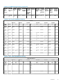
Tabelle 4. DCPMM-Konfigurationen
Anzahl
der
CPUs
im
Server
DCPMM
-
Bestück
ung
DRAM-
Bestück
ung
DRAM-
Kapazitä
t (GB)
DCPMM
-
Kapazitä
t (GB)
Betriebs
systems
peicher
im
Speiche
rmodus
(GB)
Gesamt
speicher
Gesamt
speicher
pro CPU
(GB)
Verhältn
is DRAM
zu
Optane-
Speiche
r
Erforder
t eine
M- oder
L-CPU
Unterst
ützt im
App-
Direct-
Modus
Unterst
ützt im
Speiche
rmodus
1 128 GB x
2
16 GB x
4
64 256 256 320 320 1:4 Nein Ja Ja
1 128 GB x
1
16 GB x
6
96 128 - 224 224 1:1,3 Nein Ja Nein
1 128 GB x
2
16 GB x
6
96 256 - 352 352 1:2,7 Nein Ja Nein
1 128 GB x
4
16 GB x
6
96 512 512 608 608 1:5,3 Nein Ja Ja
1 128 GB x
6
16 GB x
6
96 768 768 864 864 1:8 Nein Ja Ja
1 128 GB x
1
32 GB x
6
192 128 - 320 320 1:0,7 Nein Ja Nein
1 128 GB x
2
32 GB x
6
192 256 - 448 448 1:1,3 Nein Ja Nein
1 128 GB x
4
32 GB x
6
192 512 - 704 704 1:2,7 Nein Ja Nein
1 128 GB x
6
32 GB x
6
192 768 768 960 960 1:4 Nein Ja Ja
1 128 GB x
1
64 GB x
6
384 128 - 512 512 1:0,3 Nein Ja Nein
2 128 GB x
1
16 GB x
12
192 128 - 320 160 1:0,7 Nein Ja Nein
10 Hardware

Tabelle 4. DCPMM-Konfigurationen (fortgesetzt)
Anzahl
der
CPUs
im
Server
DCPMM
-
Bestück
ung
DRAM-
Bestück
ung
DRAM-
Kapazitä
t (GB)
DCPMM
-
Kapazitä
t (GB)
Betriebs
systems
peicher
im
Speiche
rmodus
(GB)
Gesamt
speicher
Gesamt
speicher
pro CPU
(GB)
Verhältn
is DRAM
zu
Optane-
Speiche
r
Erforder
t eine
M- oder
L-CPU
Unterst
ützt im
App-
Direct-
Modus
Unterst
ützt im
Speiche
rmodus
2 128 GB x
2
16 GB x
12
192 256 - 448 224 1:1,3 Nein Ja Nein
2 128 GB x
4
16 GB x
8
128 512 512 640 320 1:4 Nein Ja Ja
2 128 GB x
4
16 GB x
12
192 512 - 704 352 1:2,7 Nein Ja Nein
2 128 GB x
8
16 GB x
12
192 1.024 1.024 1.216 608 1:5,3 Nein Ja Ja
2 128 GB x
12
16 GB x
12
192 1.536 1.536 1.728 864 1:8 Nein Ja Ja
2 128 GB x
1
32 GB x
12
384 128 - 512 256 1:0,3 Nein Ja Nein
2 128 GB x
2
32 GB x
12
384 256 - 640 320 1:0,7 Nein Ja Nein
2 128 GB x
4
32 GB x
12
384 512 - 896 448 1:1,3 Nein Ja Nein
2 128 GB x
8
32 GB x
12
384 1.024 - 1.408 704 1:2,7 Nein Ja Nein
2 128 GB x
12
32 GB x
12
384 1.536 1.536 1.920 960 1:4 Nein Ja Ja
2 128 GB x
4
64 GB x
12
768 512 - 1.280 640 1:0,7 Nein Ja Nein
2 128 GB x
8
64 GB x
12
768 1.024 - 1.792 896 1:1,3 Nein Ja Nein
2 128 GB x
12
64 GB x
12
768 1.536 - 2.304 1.152 1:2 L SKU Ja Nein
2 128 GB x
12
128 GB x
12
1.536 1.536 - 3.072 1.536 1:1 L SKU Ja Nein
2 512 GB x
8
32 GB x
12
384 4.096 4.096 4.480 2.240 1:1,7 L SKU Ja Ja
2 512 GB x
12
32 GB x
12
384 6.144 6.144 6.528 3.264 1:16 L SKU Ja Ja
2 512 GB x
8
64 GB x
12
768 4.096 4.096 4.864 2.432 1:5,3 L SKU Ja Ja
2 512 GB x
12
64 GB x
12
768 6.144 6.144 6.912 3.456 1:8 L SKU Ja Ja
2 512 GB x
12
128 GB x
12
1.536 6.144 6.144 7.680 3.840 1:4 L SKU Ja Ja
2 256 GB x
8
16 GB x
12
192 2.048 2.048 2.240 1.120 1:10,7 L SKU Ja Ja
2 256 GB x
8
32 GB x
12
384 2.048 2.048 2.432 1.216 1:5,3 L SKU Ja Ja
Hardware 11

Tabelle 4. DCPMM-Konfigurationen (fortgesetzt)
Anzahl
der
CPUs
im
Server
DCPMM
-
Bestück
ung
DRAM-
Bestück
ung
DRAM-
Kapazitä
t (GB)
DCPMM
-
Kapazitä
t (GB)
Betriebs
systems
peicher
im
Speiche
rmodus
(GB)
Gesamt
speicher
Gesamt
speicher
pro CPU
(GB)
Verhältn
is DRAM
zu
Optane-
Speiche
r
Erforder
t eine
M- oder
L-CPU
Unterst
ützt im
App-
Direct-
Modus
Unterst
ützt im
Speiche
rmodus
2 256 GB x
12
32 GB x
12
384 3.072 3.072 3.456 1.728 1:8 L SKU Ja Ja
2 256 GB x
8
64 GB x
12
768 2.048 - 2.816 1.408 1:2,7 L SKU Ja Nein
2 256 GB x
12
64 GB x
12
768 3.072 3.072 3.840 1.920 1:4 L SKU Ja Ja
2 256 GB x
12
128 GB x
12
1.536 3.072 - 4.608 2.304 1:2 L SKU Ja Nein
4 128 GB x
16
16 GB x
24
384 2.048 2.048 2.432 608 1:5,3 Nein Ja Ja
4 128 GB x
24
16 GB x
24
384 3.072 3.072 3.456 864 1:8 Nein Ja Ja
4 128 GB x
16
32 GB x
24
768 2.048 - 2.816 704 1:2,7 Nein Ja Nein
4 128 GB x
24
32 GB x
24
768 3.072 3.072 3.840 960 1:4 Nein Ja Ja
4 128 GB x
24
64 GB x
24
1.536 3.072 - 4.608 1.152 1:2 L SKU Ja Nein
4 128 GB x
24
128 GB x
24
3.072 3.072 - 6.144 1.536 1:1 L SKU Ja Nein
4 512 GB x
16
32 GB x
24
768 8.192 8.192 8.960 2.240 1:10,7 L SKU Ja Ja
4 512 GB x
24
32 GB x
24
768 12.288 12.288 13.056 3.264 1:16 L SKU Ja Ja
4 512 GB x
16
64 GB x
24
1.536 8.192 8.192 9.728 2.432 1:5,3 L SKU Ja Ja
4 512 GB x
24
64 GB x
24
1.536 12.288 12.288 13.824 3.456 1:8 L SKU Ja Ja
4 512 GB x
24
128 GB x
24
3.072 12.288 12.288 15.360 3.840 1:4 L SKU Ja Ja
4 256 GB x
16
16 GB x
24
384 4.096 4.096 4.480 1.120 1:10,7 L SKU Ja Ja
4 256 GB x
24
16 GB x
24
384 6.144 6.144 6.528 1.632 1:16 L SKU Ja Ja
4 256 GB x
16
32 GB x
24
768 4.096 4.096 4.864 1.216 1:5,3 L SKU Ja Ja
4 256 GB x
24
32 GB x
24
768 6.144 6.144 6.912 1.728 1:8 L SKU Ja Ja
4 256 GB x
16
64 GB x
24
1.536 4.096 - 5.632 1.408 1:2,7 L SKU Ja Nein
4 256 GB x
24
64 GB x
24
1.536 6.144 6.144 7.680 1.920 1:4 L SKU Ja Ja
12 Hardware

Tabelle 4. DCPMM-Konfigurationen (fortgesetzt)
Anzahl
der
CPUs
im
Server
DCPMM
-
Bestück
ung
DRAM-
Bestück
ung
DRAM-
Kapazitä
t (GB)
DCPMM
-
Kapazitä
t (GB)
Betriebs
systems
peicher
im
Speiche
rmodus
(GB)
Gesamt
speicher
Gesamt
speicher
pro CPU
(GB)
Verhältn
is DRAM
zu
Optane-
Speiche
r
Erforder
t eine
M- oder
L-CPU
Unterst
ützt im
App-
Direct-
Modus
Unterst
ützt im
Speiche
rmodus
4 256 GB x
24
128 GB x
24
3.072 6.144 - 9.216 2.304 1:2 L SKU Ja Nein
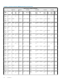
Tabelle 5. Ein-Sockel-DCPMM-Bestückung
CPU 0
Kanal 2 Kanal 1 Kanal 0 Kanal 0 Kanal 1 Kanal 2
DCP
MM
DRAM A3 A9 A2 A8 A1 A7 A10 A4 A11 A5 A12 A6
128
GB x 2
16 GB x
4
DCPM
M
DRAM DRAM DRAM DRAM DCPM
M
128
GB x 1
16 GB x
6
DRAM DRAM DRAM DCP
MM
DRAM DRAM DRAM
128
GB x 2
16 GB x
6
DRAM DRAM DRAM DCP
MM
DCPM
M
DRAM DRAM DRAM
128
GB x 4
16 GB x
6
DRAM DRAM DCPM
M
DRAM DCP
MM
DCPM
M
DRAM DCPM
M
DRAM DRAM
128
GB x 6
16 GB x
6
DRAM DCPM
M
DRAM DCPM
M
DRAM DCP
MM
DCPM
M
DRAM DCPM
M
DRAM DCPM
M
DRAM
128
GB x 1
32 GB x
6
DRAM DRAM DRAM DCP
MM
DRAM DRAM DRAM
128
GB x 2
32 GB x
6
DRAM DRAM DRAM DCP
MM
DCPM
M
DRAM DRAM DRAM
128
GB x 4
32 GB x
6
DRAM DRAM DCPM
M
DRAM DCP
MM
DCPM
M
DRAM DCPM
M
DRAM DRAM
128
GB x 6
32 GB x
6
DRAM DCPM
M
DRAM DCPM
M
DRAM DCP
MM
DCPM
M
DRAM DCPM
M
DRAM DCPM
M
DRAM
128
GB x 1
64 GB x
6
DRAM DRAM DRAM DCP
MM
DRAM DRAM DRAM
Tabelle 6. Zwei-Sockel-DCPMM-Bestückung
CPU 0 und CPU 1
Kanal 2 Kanal 1 Kanal 0 Kanal 0 Kanal 1 Kanal 2
DCP
MM
DRAM A3,
B3
A9,
B9
A2, B2 A8,
B8
A1, B1 A7,
B7
A10,
B10
A4, B4 A11,
B11
A5,
B5
A12,
B12
A6,
B6
128
GB x 1
16 GB x
12
DRAM DRAM DRAM DCP
MM
nur
auf
CPU
0
DRAM DRAM DRAM
128
GB x 2
16 GB x
12
DRAM DRAM DRAM DCP
MM
DRAM DRAM DRAM
Hardware 13

Tabelle 6. Zwei-Sockel-DCPMM-Bestückung (fortgesetzt)
CPU 0 und CPU 1
Kanal 2 Kanal 1 Kanal 0 Kanal 0 Kanal 1 Kanal 2
DCP
MM
DRAM A3,
B3
A9,
B9
A2, B2 A8,
B8
A1, B1 A7,
B7
A10,
B10
A4, B4 A11,
B11
A5,
B5
A12,
B12
A6,
B6
128
GB x 4
16 GB x
8
DCPM
M
DRAM DRAM DRAM DRAM DCPM
M
128
GB x 4
16 GB x
12
DRAM DRAM DRAM DCP
MM
DCPM
M
DRAM DRAM DRAM
128
GB x 8
16 GB x
12
DRAM DRAM DCPM
M
DRAM DCP
MM
DCPM
M
DRAM DCPM
M
DRAM DRAM
128
GB x
12
16 GB x
12
DRAM DCPM
M
DRAM DCPM
M
DRAM DCP
MM
DCPM
M
DRAM DCPM
M
DRAM DCPM
M
DRAM
128
GB x 1
32 GB x
12
DRAM DRAM DRAM DCP
MM
nur
auf
CPU
0
DRAM DRAM DRAM
128
GB x 2
32 GB x
12
DRAM DRAM DRAM DCP
MM
DRAM DRAM DRAM
128
GB x 4
32 GB x
12
DRAM DRAM DRAM DCP
MM
DCPM
M
DRAM DRAM DRAM
128
GB x 8
32 GB x
12
DRAM DRAM DCPM
M
DRAM DCP
MM
DCPM
M
DRAM DCPM
M
DRAM DRAM
128
GB x
12
32 GB x
12
DRAM DCPM
M
DRAM DCPM
M
DRAM DCP
MM
DCPM
M
DRAM DCPM
M
DRAM DCPM
M
DRAM
128
GB x 4
64 GB x
12
DRAM DRAM DRAM DCP
MM
DCPM
M
DRAM DRAM DRAM
128
GB x 8
64 GB x
12
DRAM DRAM DCPM
M
DRAM DCP
MM
DCPM
M
DRAM DCPM
M
DRAM DRAM
128
GB x
12
64 GB x
12
DRAM DCPM
M
DRAM DCPM
M
DRAM DCP
MM
DCPM
M
DRAM DCPM
M
DRAM DCPM
M
DRAM
128
GB x
12
128 GB
x 12
DRAM DCPM
M
DRAM DCPM
M
DRAM DCP
MM
DCPM
M
DRAM DCPM
M
DRAM DCPM
M
DRAM
512
GB x 8
32 GB x
12
DRAM DRAM DCPM
M
DRAM DCP
MM
DCPM
M
DRAM DCPM
M
DRAM DRAM
512
GB x
12
32 GB x
12
DRAM DCPM
M
DRAM DCPM
M
DRAM DCP
MM
DCPM
M
DRAM DCPM
M
DRAM DCPM
M
DRAM
512
GB x 8
64 GB x
12
DRAM DRAM DCPM
M
DRAM DCP
MM
DCPM
M
DRAM DCPM
M
DRAM DRAM
512
GB x
12
64 GB x
12
DRAM DCPM
M
DRAM DCPM
M
DRAM DCP
MM
DCPM
M
DRAM DCPM
M
DRAM DCPM
M
DRAM
14 Hardware

Tabelle 6. Zwei-Sockel-DCPMM-Bestückung (fortgesetzt)
CPU 0 und CPU 1
Kanal 2 Kanal 1 Kanal 0 Kanal 0 Kanal 1 Kanal 2
DCP
MM
DRAM A3,
B3
A9,
B9
A2, B2 A8,
B8
A1, B1 A7,
B7
A10,
B10
A4, B4 A11,
B11
A5,
B5
A12,
B12
A6,
B6
512
GB x
12
128 GB
x 12
DRAM DCPM
M
DRAM DCPM
M
DRAM DCP
MM
DCPM
M
DRAM DCPM
M
DRAM DCPM
M
DRAM
256
GB x 8
16 GB x
12
DRAM DRAM DCPM
M
DRAM DCP
MM
DCPM
M
DRAM DCPM
M
DRAM DRAM
256
GB x 8
32 GB x
12
DRAM DRAM DCPM
M
DRAM DCP
MM
DCPM
M
DRAM DCPM
M
DRAM DRAM
256
GB x
12
32 GB x
12
DRAM DCPM
M
DRAM DCPM
M
DRAM DCP
MM
DCPM
M
DRAM DCPM
M
DRAM DCPM
M
DRAM
256
GB x 8
64 GB x
12
DRAM DRAM DCPM
M
DRAM DCP
MM
DCPM
M
DRAM DCPM
M
DRAM DRAM
256
GB x
12
64 GB x
12
DRAM DCPM
M
DRAM DCPM
M
DRAM DCP
MM
DCPM
M
DRAM DCPM
M
DRAM DCPM
M
DRAM
256
GB x
12
128 GB
x 12
DRAM DCPM
M
DRAM DCPM
M
DRAM DCP
MM
DCPM
M
DRAM DCPM
M
DRAM DCPM
M
DRAM
Tabelle 7. Vierfachsockel-DCPMM-Bestückung
CPU 0, CPU 1, CPU 2 und CPU 3
Kanal 2 Kanal 1 Kanal 0 Kanal 0 Kanal 1 Kanal 2
DCP
MM
DRAM A3,
B3,
C3
A9,
B9,
C9
A2, B2,
C2
A8,
B8,
C8
A1,
B1, C1
A7,
B7,
C7
A10,
B10,
C10
A4, B4,
C4
A11,
B11,
C11
A5,
B5,
C5
A12,
B12,
C12
A6,
B6,
C6
128
GB x
16
16 GB x
24
DRAM DRAM DCPM
M
DRAM DCP
MM
DCPM
M
DRAM DCPM
M
DRAM DRAM
128
GB x
24
16 GB x
24
DRAM DCPM
M
DRAM DCPM
M
DRAM DCP
MM
DCPM
M
DRAM DCPM
M
DRAM DCPM
M
DRAM
128
GB x
16
32 GB x
24
DRAM DRAM DCPM
M
DRAM DCP
MM
DCPM
M
DRAM DCPM
M
DRAM DRAM
128
GB x
24
32 GB x
24
DRAM DCPM
M
DRAM DCPM
M
DRAM DCP
MM
DCPM
M
DRAM DCPM
M
DRAM DCPM
M
DRAM
128
GB x
24
64 GB x
24
DRAM DCPM
M
DRAM DCPM
M
DRAM DCP
MM
DCPM
M
DRAM DCPM
M
DRAM DCPM
M
DRAM
128
GB x
24
128 GB
x 24
DRAM DCPM
M
DRAM DCPM
M
DRAM DCP
MM
DCPM
M
DRAM DCPM
M
DRAM DCPM
M
DRAM
512
GB x
16
32 GB x
24
DRAM DRAM DCPM
M
DRAM DCP
MM
DCPM
M
DRAM DCPM
M
DRAM DRAM
Hardware 15

Tabelle 7. Vierfachsockel-DCPMM-Bestückung (fortgesetzt)
CPU 0, CPU 1, CPU 2 und CPU 3
Kanal 2 Kanal 1 Kanal 0 Kanal 0 Kanal 1 Kanal 2
DCP
MM
DRAM A3,
B3,
C3
A9,
B9,
C9
A2, B2,
C2
A8,
B8,
C8
A1,
B1, C1
A7,
B7,
C7
A10,
B10,
C10
A4, B4,
C4
A11,
B11,
C11
A5,
B5,
C5
A12,
B12,
C12
A6,
B6,
C6
512
GB x
24
32 GB x
24
DRAM DCPM
M
DRAM DCPM
M
DRAM DCP
MM
DCPM
M
DRAM DCPM
M
DRAM DCPM
M
DRAM
512
GB x
16
64 GB x
24
DRAM DRAM DCPM
M
DRAM DCP
MM
DCPM
M
DRAM DCPM
M
DRAM DRAM
512
GB x
24
64 GB x
24
DRAM DCPM
M
DRAM DCPM
M
DRAM DCP
MM
DCPM
M
DRAM DCPM
M
DRAM DCPM
M
DRAM
512
GB x
24
128 GB
x 24
DRAM DCPM
M
DRAM DCPM
M
DRAM DCP
MM
DCPM
M
DRAM DCPM
M
DRAM DCPM
M
DRAM
256
GB x
16
16 GB x
24
DRAM DRAM DCPM
M
DRAM DCP
MM
DCPM
M
DRAM DCPM
M
DRAM DRAM
256
GB x
24
16 GB x
24
DRAM DCPM
M
DRAM DCPM
M
DRAM DCP
MM
DCPM
M
DRAM DCPM
M
DRAM DCPM
M
DRAM
256
GB x
16
32 GB x
24
DRAM DRAM DCPM
M
DRAM DCP
MM
DCPM
M
DRAM DCPM
M
DRAM DRAM
256
GB x
24
32 GB x
24
DRAM DCPM
M
DRAM DCPM
M
DRAM DCP
MM
DCPM
M
DRAM DCPM
M
DRAM DCPM
M
DRAM
256
GB x
16
64 GB x
24
DRAM DRAM DCPM
M
DRAM DCP
MM
DCPM
M
DRAM DCPM
M
DRAM DRAM
256
GB x
24
64 GB x
24
DRAM DCPM
M
DRAM DCPM
M
DRAM DCP
MM
DCPM
M
DRAM DCPM
M
DRAM DCPM
M
DRAM
256
GB x
24
128 GB
x 24
DRAM DCPM
M
DRAM DCPM
M
DRAM DCP
MM
DCPM
M
DRAM DCPM
M
DRAM DCPM
M
DRAM
512
GB x
12
64 GB x
12
DRAM DCPM
M
DRAM DCPM
M
DRAM DCP
MM
DCPM
M
DRAM DCPM
M
DRAM DCPM
M
DRAM
512
GB x
12
128 GB
x 12
DRAM DCPM
M
DRAM DCPM
M
DRAM DCP
MM
DCPM
M
DRAM DCPM
M
DRAM DCPM
M
DRAM
256
GB x 8
16 GB x
12
DRAM DRAM DCPM
M
DRAM DCP
MM
DCPM
M
DRAM DCPM
M
DRAM DRAM
256
GB x 8
32 GB x
12
DRAM DRAM DCPM
M
DRAM DCP
MM
DCPM
M
DRAM DCPM
M
DRAM DRAM
256
GB x
12
32 GB x
12
DRAM DCPM
M
DRAM DCPM
M
DRAM DCP
MM
DCPM
M
DRAM DCPM
M
DRAM DCPM
M
DRAM
16 Hardware

Tabelle 7. Vierfachsockel-DCPMM-Bestückung (fortgesetzt)
CPU 0, CPU 1, CPU 2 und CPU 3
Kanal 2 Kanal 1 Kanal 0 Kanal 0 Kanal 1 Kanal 2
DCP
MM
DRAM A3,
B3,
C3
A9,
B9,
C9
A2, B2,
C2
A8,
B8,
C8
A1,
B1, C1
A7,
B7,
C7
A10,
B10,
C10
A4, B4,
C4
A11,
B11,
C11
A5,
B5,
C5
A12,
B12,
C12
A6,
B6,
C6
256
GB x 8
64 GB x
12
DRAM DRAM DCPM
M
DRAM DCP
MM
DCPM
M
DRAM DCPM
M
DRAM DRAM
256
GB x
12
64 GB x
12
DRAM DCPM
M
DRAM DCPM
M
DRAM DCP
MM
DCPM
M
DRAM DCPM
M
DRAM DCPM
M
DRAM
256
GB x
12
128 GB
x 12
DRAM DCPM
M
DRAM DCPM
M
DRAM DCP
MM
DCPM
M
DRAM DCPM
M
DRAM DCPM
M
DRAM
CPU-Typ und Beschränkungen für die maximale
Speicherkapazität
Tabelle 8. CPU-Typ und Beschränkungen für die maximale Speicherkapazität
CPU-Typ Maximal unterstützte Speicherkapazität
(Einschließlich der Kapazität für flüchtigen und
persistenten Speicher)
Alle CPU-SKUs 1 TB pro CPU-Sockel
M-SKUs 2 TB pro CPU-Sockel
L-SKUs 4,5 TB pro CPU-Sockel
DCPMM-Kombinierungs- und Bestückungsregeln
In diesem Abschnitt finden Sie allgemeine Regeln zum Kombinieren und Bestücken von DIMM-Speicher.
Jedes System darf nur eine Kapazität von DCPMM enthalten. Wenn Sie verschiedene DCPMM-Kapazitäten miteinander kombinieren,
wird eine F1/F2-Warnmeldung angezeigt. Dies ist keine unterstützte Konfiguration und darf nicht bestückt werden. Die Tabelle „DCPMM-
Konfigurationen“ ersetzt die folgenden Regeln:
Regeln zum Kombinieren
• DCPMMs können mit RDIMMs, LRDIMMs und 3DS-LRDIMMs kombiniert werden.
• Die Kombination von DDR4-DIMM-Typen (RDIMM, LRDIMM, 3DS-LRDIMM) in einem Kanal, iMC, Sockel oder über mehrere Sockeln
hinweg wird nicht unterstützt.
• x4- und x8-DDR4-DIMMs können in einem Kanal kombiniert werden.
• Die Kombination von DCPMM-Betriebsmodi (App Direct, Speichermodus) wird nicht unterstützt.
Bestückungsregeln
• Maximal ein DCPMM pro Kanal.
• Wenn nur ein DIMM in einem Kanal bestückt wird, sollte es immer in den ersten Steckplatz in diesem Kanal eingesetzt werden (weißer
Steckplatz).
• Wenn ein DCPMM und ein DDR4-DIMM im selben Kanal bestückt werden, muss das DCPMM immer in den zweiten Steckplatz
(schwarzer Steckplatz) eingesetzt werden.
• Wenn das DCPMM im Speichermodus konfiguriert ist, beträgt die empfohlene DDR4-zu-DCPMM-Kapazitätsrate 1:4 bis 1:16 pro iMC.
Hardware
17

BIOS
Themen:
• BIOS-Konfigurationseinstellung für Intel DCPMM
• App-Direct-Modus-Konfiguration
• Speichermoduskonfiguration
BIOS-Konfigurationseinstellung für Intel DCPMM
DIMM-Erkennung
Alle installierten DCPMMs, die das BIOS während der Systembestandsaufnahme erkannt hat, werden auf der Registerkarte „Intel
Persistent Memory“ im BIOS angezeigt:
Memory Settings > Persistent Memory > Intel Persistent Memory > Persistent Memory DIMM Configuration.
Abbildung 2. Bildschirm „Persistent Memory“
ANMERKUNG: DCPMMs werden als DIMMs angezeigt.
Es gibt einen Eintrag für jedes installierte DCPMM und die aktuellen Funktionszustands- und Statusinformationen für jedes DCPMM
werden wie folgt angezeigt:
4
18 BIOS

Abbildung 3. Memory Info
ANMERKUNG:
Die Daten sind immer in MiB/GiB/TiB-Einheiten zu betrachten, auch wenn die Bezeichnungen
MB/GB/TB verwendet werden. Der Overhead für die Benutzerkapazität beträgt bis zu 2 % der Kapazität (GiB).
Möglicherweise ist ein weiterer Overhead für Regionen, Namespaces und Dateisysteme erforderlich.
App-Direct-Modus-Konfiguration
Ziel erstellen
Ein Ziel wird im BIOS erstellt.
Um ein Ziel im BIOS zu erstellen, navigieren Sie zu: Memory Settings (Speichereinstellungen)Persistent Memory (Persistenter
Speicher)Intel Persistent Memory (Persistenter Intel Speicher)Region Configuration (Regionskonfiguration)Create Goal
Config (Zielkonfiguration erstellen).
BIOS
19

Abbildung 4. Zielkonfiguration
Die BIOS-Optionen legen fest, wie das Ziel erstellt und die DCPMMs konfiguriert werden:
Persistent [%]:
• No Change (Keine Änderung): Es werden keine Änderungen auf das aktuelle Ziel angewendet.
• 100: Ein Ziel von 100 % persistentem Speicher für die ausgewählten DCPMMs wird erstellt.
• 0 – Ein Ziel von 0 % persistentem Speicher für die ausgewählten DCPMMs wird erstellt. Dieser Vorgang konfiguriert alle DCPMMs als
Speichermodus.
Typ des persistenten Speichers:
• App-Direct Interleaved: Interleaving im persistenten Modus wird für alle DCPMMs in einem Sockel. Die DCPMMs werden für ein
PMEM-Gerät pro Sockel im Betriebssystem angezeigt.
• App-Direct Not Interleaved: Der persistente Modus wird für jedes DCPMM einzeln angewendet. Jedes DCPMM wird als einzelnes
PMEM-Gerät im Betriebssystem angezeigt.
Nachdem das Ziel konfiguriert und das BIOS verlassen wurde, wird das Ziel für die DCPMMs mit den vom Benutzer festgelegten
Einstellungen während des nächsten Starts erstellt.
Regionsinformationen
Informationen über jede Region, die während des Vorgangs Create Goal Config erstellt wird, können nach einem System-Reset auf der
Registerkarte Regions Configuration im BIOS aufgerufen werden:
Memory Settings > Persistent Memory > Intel Persistent Memory > Region Configuration.
20
BIOS
Seite laden ...
Seite laden ...
Seite laden ...
Seite laden ...
Seite laden ...
Seite laden ...
Seite laden ...
Seite laden ...
Seite laden ...
Seite laden ...
Seite laden ...
Seite laden ...
Seite laden ...
Seite laden ...
Seite laden ...
Seite laden ...
Seite laden ...
Seite laden ...
Seite laden ...
Seite laden ...
Seite laden ...
Seite laden ...
Seite laden ...
Seite laden ...
Seite laden ...
Seite laden ...
Seite laden ...
Seite laden ...
-
 1
1
-
 2
2
-
 3
3
-
 4
4
-
 5
5
-
 6
6
-
 7
7
-
 8
8
-
 9
9
-
 10
10
-
 11
11
-
 12
12
-
 13
13
-
 14
14
-
 15
15
-
 16
16
-
 17
17
-
 18
18
-
 19
19
-
 20
20
-
 21
21
-
 22
22
-
 23
23
-
 24
24
-
 25
25
-
 26
26
-
 27
27
-
 28
28
-
 29
29
-
 30
30
-
 31
31
-
 32
32
-
 33
33
-
 34
34
-
 35
35
-
 36
36
-
 37
37
-
 38
38
-
 39
39
-
 40
40
-
 41
41
-
 42
42
-
 43
43
-
 44
44
-
 45
45
-
 46
46
-
 47
47
-
 48
48


Dell PowerEdge R740xd Benutzerhandbuch
- Typ
- Benutzerhandbuch
- Dieses Handbuch ist auch geeignet für
Verwandte Papiere
-
Dell PowerEdge R740xd Benutzerhandbuch
-
-
-
-
Dell PowerEdge R940 Bedienungsanleitung
-
Dell PowerEdge MX7000 Bedienungsanleitung
-
-
Dell PowerEdge R940xa Bedienungsanleitung
-
Dell PowerEdge R840 Bedienungsanleitung
-