Seite wird geladen ...

Advanced Contact Technology
1 / 4
green-yellow
black
red
blue
yellow
green
violet
brown
grey
white
transparent
2021 22 23 24 25 26 27 28 29 33
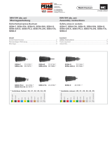
Available colours: 21-29
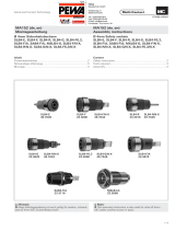
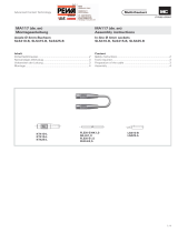
SAB4-G
23.3050-*
SAB4-G/N-X
49.7042-* SAB4-GT/N
49.4010-20
SPK4
23.0410-*
Available colours: 21-29
Available colours: 21-22
MA153 (de_en)
Montageanleitung
MA153 (de_en)
Assembly instructions
Sicherheitsbuchsen SAB4-G,
SAB4-G/N-X, SAB4-GT/N, SPK4
Safety sockets SAB4-G,
SAB4-G/N-X, SAB4-GT/N, SPK4
Inhalt
Sicherheitshinweise....................................................................2
Notwendiges Werkzeug ............................................................3
Montage ....................................................................................3
Content
Safety Instructions ......................................................................2
Tools required ............................................................................3
Assembly ................................................................................... 3
grün-gelb
schwarz
rot
blau
gelb
grün
violett
braun
grau
weiss
transparent
2021 22 23 24 25 26 27 28 29 33
Lieferbare Farben: 21-29 Lieferbare Farben: 21-29
Lieferbare Farben: 21-22
Hinweis:
Diese Montageanleitung ist auch gültig für andere, schraub-
bare Ø 4mm MC Sicherheitsbuchsen.
Note:
This assembly instruction is also valid for other Ø 4mm
MC safety sockets (screw-in type).

Advanced Contact Technology
2 / 4
Erklärung der Symbole Explanation of the symbols
Warnung vor gefährlicher elektrischer Spannung Warning of dangerous voltages
Warnung vor einer Gefahrenstelle Warning of a hazard area
Nützlicher Hinweis oder Tipp Useful hint or tip
Sicherheitshinweise Safety instructions
Die Montage und Installation der Produkte darf ausschliess-
lich durch qualifi ziertes und erfahrenes Fachpersonal unter
Berücksichtigung aller anwendbaren gesetzlichen Sicher-
heitsbestimmungen und Regelungen erfolgen.
Multi-Contact (MC) lehnt jegliche Haftung infolge Nichteinhal-
tung dieser Warnhinweise ab.
The products may be assembled and installed exclusively by
suitably qualifi ed and trained specialists duly observing all ap-
plicable safety regulations.
Multi-Contact (MC) does not accept any liability in the event of
failure to observe these warnings.
Benutzen Sie nur die von MC angegebenen Einzelteile und
Werkzeuge. Weichen Sie nicht von den hier beschriebenen
Vorgängen zur Vorbereitung und Montage ab, da sonst bei der
Selbstkonfektionierung weder die Sicherheit noch die Einhal-
tung der technischen Daten gewährleistet ist. Ändern Sie das
Produkt nicht in irgend einer Weise ab.
Use only the components and tools specifi ed by MC. In case
of self-assembly, do not deviate from the preparation and as-
sembly instructions as stated herein, otherwise MC cannot
give any guarantee as to safety or conformity with the techni-
cal data. Do not modify the product in any way.
Der Schutz vor einem elektrischen Schlag müssen
bei Installation und Montage/Demontage immer
alle Bauteile spannungsfrei sein.
For protection against electric shock, parts must
be isolated from the power supply while being as-
sembled or disassembled.
Die Steckverbindungen dürfen nicht unter Last
getrennt werden. Das Stecken und Trennen unter
Spannung ist zulässig.
The plug connections must not be disconnected
under load. Plugging and unplugging when live is
permitted.
Vor jedem Gebrauch ist durch Besichtigen (im be-
sonderen die Isolation) zu prüfen, ob keine äusseren
Mängel vorhanden sind. Wenn Zweifel bezüglich der
Sicherheit bestehen, muss ein Fachmann hinzuge-
zogen werden oder der Steckverbinder muss ausge-
tauscht werden.
Each time the connector is used, it should previously
be inspected for external defects (particularly in the
insulation). If there are any doubts as to its safety, a
specialist must be consulted or the connector must
be replaced.
Weitere technische Daten entnehmen Sie bitte dem
Produktkatalog.
For further technical data please see the product
catalogue.

Advanced Contact Technology
3 / 4
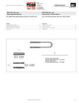
3
1
4
2
5
6
Notwendiges Werkzeug Tools required
(ill. 1)
Bohrer Ø 8.2mm für SAB4-G,
SAB4-G/N-X und SAB4-GT/N.
Bohrer Ø 10mm für SPK4.
(ill. 1)
Drill Ø 8.2mm for SAB4-G,
SAB4-G/N-X and SAB4-GT/N.
Drill Ø 10mm for SPK4.
(ill. 2)
Drehmomentschlüssel 7mm für SAB4-G,
SAB4-G/N-X und SAB4-GT/N.
Drehmomentschlüssel 8mm für SPK4.
(ill. 2)
Torque spanner 7mm for SAB4-G,
SAB4-G/N-X and SAB4-GT/N.
Torque spanner 8mm for SPK4.
(ill. 3)
Spezialschlüssel SS2
(Bestell-Nr. 25.0022) für SAB4-G,
SAB4-G/N-X und SAB4-GT/N.
(ill. 3)
Special tube spanner SS2
(Order No. 25.0022) for SAB4-G,
SAB4-G/N-X and SAB4-GT/N.
Montage Assembly
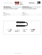
(ill. 4)
Fronttafel bohren.
Bohrung für SAB4-G, SAB4-G/N-X
und SAB4-GT/N: 8,2mm.
Bohrung für SPK4: 10mm.
Plattenstärke: für SAB4-G, SAB4-G/N-X,
SAB4-GT/N: max. 3mm.
Für SPK4: max. 4mm
Als Aufl age der Fronttafel wird
vorzugsweise ein Kunststoffrohr
verwendet. Der Durchmesser des
Aufl agerohres richtet sich nach den
gewählten Lochabständen.
(ill. 4)
Drill hole in the front panel.
For SAB4-G, SAB4-G/N-X and
SAB4-GT/N: 8.2mm.
For SPK4: 10mm.
Panel thickness: for SAB4-G,
SAB4-G/N-X, SAB4-GT/N: max. 3mm.
For SPK4: max. 4mm
As an assembly support for the front
panel, a plastic tube can be used.
The tube diameter depends upon
the desire d spacings between the
sockets.
(ill. 5)
Sicherheitsbuchse in Fronttafel
stecke n.
(ill. 5)
Place safety socket into the front
panel.
(ill. 6)
Von der Rückseite her Gegenstück (G),
Unterlegscheiben und Muttern in der
gezeigten Reihenfolge aufstecken
bzw. aufschrauben.
(ill. 6)
From the back, in the order shown,
assemble the insulator (G), the wash-
ers and nuts.

Advanced Contact Technology
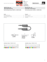
10
9
8
7
© by Multi-Contact AG, Switzerland – MA153 – 04.2013, Index d, Global Communications – Änderungen vorbehalten / Subject to alterations
(ill. 7)
Mutter von Hand leicht anziehen.
(ill. 7)
Lightly tighten the nut by hand.
(ill. 8)
(gilt nur für SAB4-G, SAB4-G/N-X
und SAB4-GT/N):
Mit dem Drehmomentschlüssel (7mm)
die Befestigungsmutter (a) anziehen
und gleichzeitig den Spezialschlüs-
sel SS2 zum Kontern in die Buchse
stecken, bis er in den dafür vorgese-
henen Vertiefungen einrastet.
Anzugsdrehmoment: max. 70Ncm.
(gilt nur für SPK4):
Mit dem Gabelschlüssel (8mm) die
Befestigungsmutter (a) anziehen und
dabei die Sicherheitsbuchse mit der
Hand festhalten.
Anzugsdrehmoment: max. 70Ncm.
(ill. 8)
(applies only to SAB4-G, SAB4-
G/N-X and SAB4-GT/N):
Using the torque spanner (7mm),
tighten the fi xing nut (a) and at the
same time, in order to counter-tighten,
insert the special wrench SS2 into the
socket until it engages in the recess
provided.
Tightening torque: max. 70Ncm.
(applies only to SPK 4):
Using an open-ended spanner (8mm),
screw down the fi xing nut (a) while
holding the safety socket fi rm in the
hand.
Tightening torque: max. 70Ncm.
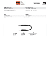
(ill. 9)
Zum Anschliessen der Leitung die
Spannscheiben und die Mutter in der
gezeigten Reihenfolge aufstecken
bzw. aufschrauben.
(ill. 9)
To connect the cable, fi t the spring
washers and screw on the nut in the
order shown.
(ill. 10)
Wichtig:
Beim Anziehen der Mutter (b) muss
mit der Mutter (a) gekontert werden!
(ill. 10)
Important:
When tightening nut (b), nut (a) must
be used to counter.
/