
User and Maintenance
Instructions
Grill
(Gas)
Handleiding Voor
Bediening En Onderhoud
Grillen
(Gas)
Betriebs- und
Wartungsanleitung
Grill
(Gasbetrieb)
Manuel d’Utilisation et
de Maintenance
Gril
(A Gaz)

2
Table of Contents / Inhoudsopgave /
Inhaltsverzeichnis / Table des Matières
I. ENGLISH ………………………………………………………………. 3
A. Description
B. Products
C. Mounting Instructions
D. Operator Instructions and Attention Points
E. Figures
F. Product Drawings
II. NEDERLANS ………………………………………………………… 17
A. Beschrijving
B. Producten
C. Montage-Instructies
D. Instructies van de bediener en aandachtspunten
E. Figuur
F. Producttekeningen
III. DEUTSCH ……………………………………………………………. 31
A. Beschreibung
B. Produkte
C. Installationsanleitung
D. Benutzerhinweise und zu Beachtende Punkte
E. Abbildung
F. Produktzeichnungen
IV. FRANÇAIS …………………………………………………………… 45
A. Explications
B. Des Produits
C. Instructions de Montage
D. Instructions a L’utilisateur et Points a Considérer
E. Les Figures
F. Dessins des Produits

3
User and Maintenance
Instructions
Grill (Gas)

4
A. DESCRIPTION
Our dear customer,
Your preferred COMBISTEEL is nature and technology friendly. We thank you for your
choice.
COMBISTEEL has been produced with the understanding of "Total Quality" in modern
production facilities.
Important Safety Information
Carefully read this guide and keep it for future review.
WARNING: Installation of the devices must be done by an authorized service person.
WARNING: Equipment must be grounded.
Indicates that there is a risk of personal injury or property damage.
Explosion / fire hazard
B. PRODUCTS
CODE
DESCRIPTION
SERIE
7178.0025
7178.0055
Gas griddle plate, tabletop model, smooth plate / Gas griddle
plate, tabletop model, smooth chromed plate
600
7178.0030
7178.0060
Gas griddle plate, tabletop model, smooth plate / Gas griddle
plate, tabletop model, smooth chromed plate
600
7178.0445
7178.0475
Gas griddle plate, smooth plate / Gas griddle plate, smooth
chromed plate
700
7178.0450
7178.0480
Gas griddle plate, smooth plate / Gas griddle plate, smooth
chromed plate
700
7178.0225
7178.0255
Gas griddle plate, tabletop model, smooth plate / Gas griddle
plate, tabletop model, smooth chromed plate
700S
7178.0230
7178.0260
Gas griddle plate, tabletop model, smooth plate / Gas griddle
plate, tabletop model, smooth chromed plate
700S
7178.0262
Gas griddle plate, tabletop model, 1/2 chrome ribbed plate
700S
7178.3150
7178.3185
Gas griddle plate, smooth plate / Gas griddle plate, smooth
chromed plate
900
7178.3155
7178.3190
Gas griddle plate, smooth plate / Gas griddle plate, smooth
chromed plate
900

5
C. MOUNTING INSTRUCTION
Placement
Installation and adjustment of the device should be carried out by technical staff of the
Authorized Service.
Place the device beneath a filtered exhaust hood in order to eliminate smell and fume
that may be emitted during cooking.
Place the device at a place min. 10cm away from the side or back wall to prevent
excessive temperature rises.
Device should be placed on a flat surface by suitably balancing on the four adjustable
legs. (Figure A)
Remove the protective nylon on the device. Clean the adhesive particles left on the
device with a suitable cleaner.
Never leave flammable material near the device.
Gas Connection
Device should be connected in accordance with the national and local gas standards of
the relevant country.
Gas inlets of the device are indicated with a label “GAS” on device body.
Connection to the gas installation should be made with flex pipe and ball valve. Fix the
said ball valve to a place that is away from heat and easily accessible in case of a
danger.After gas inlet connection is completed, check for possible gas leakages.
Feed the device with the gas and pressure as specified on device information plate and
adjusted. If the gas type to which the device was adjusted for is not suitable to the gas
type at the mounted place, follow the instructions written below.
ATTENTION: All adjustments and modifications to be performed on the gas installation and
connection of the device should be performed by authorized people. Gas pressure may never
exceed 21mbar for Natural gas and 30mbar for LPG.

6
ADJUSTMENT ACCORDING TO DIFFERENT GAS TYPES
If the device is connected to gas installation, close main gas inlet valve.
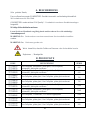
Replacement of burner nozzles (Figure B)
1. Dissemble front panel of the grill. Unscrew the nozzle at the burner inlet using a
suitable wrench (1).
2. Replace nozzle (2) with a nozzle suitable for the gas type to be used
3. Replace the flame nozzles of pilot burner (4) with a nozzle suitable for the gas type.
For this purpose, it is enough to dismantle coupling (3) and pull the gas pipe down.
4. The venturi (Gas/Air tube) adjust part gap should be should be full open LPG & NG
gas type.
5. After adjust of venturi tube gap, tight to the bolt with a suitable wrench.
6. The air/gas venturi adjust part gap should full opened and fixed, the gap will be 45 mm
for the accurate burning.

7
D. OPERATOR INSTRUCTIONS AND ATTENTION POINTS
Before cooking with the grill, operate it with no load for a while. Thus, the protection
oil on it will disappear and it will become ready to use.
When you do not cook, keep the adjustment button on half flame " " or pilot position.
It will provide a more economical usage for you.
Clean the grill platina using suitable scraper every day. In this way, you prevent the
accumulation of burned and carbonized foods, and accordingly any decrease in the
cooking efficiency.
Clean the oil drawer inside the cabinet after each use.
If you will not use the grill for a long time, cover the grill platina with suitable liquid oil
and keep away from moisture.
Do not operate the grill with its back funnel mouldings removed or closed.
Never leave any uncovered food in the cabinet section of the devices.
START-UP
Turn the main gas valve to open position.
Turn the grill gas button (5) to lighter position " " by pushing it gently. In this
position, ignite (6) the pilot burner with lighter.
After the pilot is ignited, keep the button pressed for a few seconds (min. 10) to heat the
safety thermocouple end.
Later, you can adjust it to the desired position by turning to high flame " " or low
flame " " marks indicated on button.
If the device is operated for the first time, keep the button pressed at pilot burner flame
position for a while before ignition to discharge the air in the gas installation.
TURNING OFF
Turn the gas button to lighter position " ". In this position, only pilot burn occurs.
Turn to position “0” to turn off completely.
MAINTENANCE
Never perform maintenance without closing the main gas valve of the device.
Before it cools down completely, wipe the device with a cloth immersed in warm soapy
water.
Do not use cleaning substances and tools that may cause scratches on device surface.
If required, use chemical cleaners.
Do not clean the device with pressurized water or vapour.
If the device will not be used for a long time, coat the surfaces with a thin layer of
Vaseline.

8
ATTENTION: Any part replacement that may affect safety must be carried out by the authorized people.
During maintenance and repair, keep the main gas valve closed and keep away fire. Always perform
leakage check after repair or part replacement; use foam or gas detector for this aim. In case of any
dangerous condition with the device, notify to the authorized service. Do not allow unauthorized people
to interfere in the device.
DANGEROUS: Never allow leakage check to be performed with flame
Compatibility Information
This device is designed and manufactured in accordance with the following directives and
standards.
marking directive, 93/68/EEC
TS EN 203-1 / Gas Powered Cooking Appliances – Part 1:General Safety Appliances
TS EN 203-2-1 Gas Fired Catering Equipments - Part 2-1: Specifications – Open-tops
TS EN 203-2-2 Gas Burning Devices – Part 2-2: Special Rules – Ovens
Limitation of Liability: All technical information contained in this manual, operating
instructions, operation and maintenance of the device, contains the latest information on
your device. The manufacturer accepts no responsibility for damage or injury which may
result from failure to follow the instructions in this manual, use outside of the intended
use, unauthorized repair, unauthorized modifications to the device, or use of spare parts
not approved by the manufacturer.

9
E. FIGURES
Figure A
Figure B

10
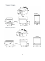
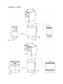
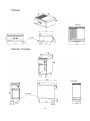
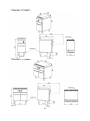
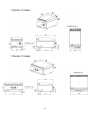
F. PRODUCT DRAWINGS
Product
Width
(W)
Depth
(D)
Height
(H)
Gas
Inlet
Power
Working Gas
Pressure
Weight
Volume
7178.0025
7178.0055
400 mm
600 mm
300 mm
1/2"
5,8 kW
NG-G20-20mBar
LPG-G30-30mBar
35 kg
0.18 m3
7178.0030
7178.0060
600 mm
600 mm
300 mm
1/2"
7,16 kW
NG-G20-20mBar
LPG-G30-30mBar
50 kg
0.28 m3
7178.0445
7178.0475
400 mm
700 mm
900 mm
1/2"
6,5 kW
NG-G20-20mBar
LPG-G30-30mBar
83 kg
0.45 m3
7178.0450
7178.0480
800 mm
700 mm
900 mm
1/2"
13 kW
NG-G20-20mBar
LPG-G30-30mBar
126 kg
0.84 m3
7178.0225
7178.0255
400 mm
700 mm
300 mm
1/2"
6,5 kW
NG-G20-20mBar
LPG-G30-30mBar
70 kg
0.21 m3
7178.0230
7178.0260
800 mm
700 mm
300 mm
1/2"
13 kW
NG-G20-20mBar
LPG-G30-30mBar
115 kg
0.36 m3
7178.0262
800 mm
700 mm
300 mm
1/2"
13 kW
NG-G20-20mBar
LPG-G30-30mBar
120 kg
0.36 m³
7178.3150
7178.3185
400 mm
900 mm
900 mm
1/2"
9 kW
NG-G20-20mBar
LPG-G30-30mBar
87 kg
0.55 m³
7178.3155
7178.3190
800 mm
900 mm
900 mm
1/2"
18 kW
NG-G20-20mBar
LPG-G30-30mBar
152 kg
1.05 m³

11
7178.0025 / 7178.0055
7178.0030 / 7178.0060

12
7178.0445 / 7178.0475
7178.0450 / 7178.0480

13
7178.0225 / 7178.0255
7178.0230 / 7178.0260

14
7178.0262
7178.3150 / 7178.3185

15
7178.3155 / 7178.3190

16
SERIE 700 / 900 Fixation
600 / 700-S series equipment fixation scheme

17
Handleiding Voor Bediening
En Onderhoud
Grillen (Gas)

18
A. BESCHRIJVING
Beste klanten,
Uw gewenste COMBISTEEL-product is natuur- en technologievriendelijk. Wij danken
u voor uw keuze.
COMBISTEEL is vervaardigd met het begrip '' Volledige Kwaliteit ''in zijn moderne
productiefaciliteiten.
Belangrijke veiligheidsinformatie
Lees deze handleiding aandachtig door en bewaar deze voor toekomstige
beoordelingen.
WAARSCHUWING: De apparaten moeten worden geïnstalleerd door een
gekwalificeerdeonderhoudsmonteur.
WAARSCHUWING: De apparatuur moet worden geaard.
Geeft aan dat er een risico bestaat op persoonlijk letsel of materiële schade.
Explosie / brandgevaar.
CODE
BESCHRIJVING
SERIE
7178.0025
7178.0055
Gasbakplaat, tafelmodel, gladde plaat / Gasbakplaat plaat,
tafelmodel, glad verchroomde plaat
600
7178.0030
7178.0060
Gasbakplaat, tafelmodel, gladde plaat / Gasbakplaat plaat,
tafelmodel, glad verchroomde plaat
600
7178.0445
7178.0475
Gasbakplaat, gladde plaat / Gasbakplaat plaat, glad verchroomde
plaat
700
7178.0450
7178.0480
Gasbakplaat, gladde plaat / Gasbakplaat plaat, glad verchroomde
plaat
700
7178.0225
7178.0255
Gasbakplaat, tafelmodel, gladde plaat / Gasbakplaat plaat,
tafelmodel, glad verchroomde plaat
700S
7178.0230
7178.0260
Gasbakplaat, tafelmodel, gladde plaat / Gasbakplaat plaat,
tafelmodel, glad verchroomde plaat
700S
7178.0262
Gasbakplaat, tafelmodel, 1/2 chromen geribbelde plaat
700S
7178.3150
7178.3185
Gasbakplaat, gladde plaat / Gasbakplaat plaat, glad verchroomde
plaat
900
7178.3155
7178.3190
Gasbakplaat, gladde plaat / Gasbakplaat plaat, glad verchroomde
plaat
900

19
B. PRODUCTEN
C. MONTAGE-INSTRUCTIES
INSTALLATIE INSTRUCTIES
Installatie en afstelling van het apparaat moet worden uitgevoerd door de technische
dienst van de erkende servicedienst.
Plaats het apparaat onder een gefilterde afzuigkap om alle geuren en dampen te
verwijderen die vrijkomen tijdens het koken.
Plaats het apparaat op minstens 10 centimeter afstand van de zijwand of achterwand
om overmatige temperatuurstijging te voorkomen.
Het apparaat moet op een vlak oppervlak worden geplaatst, op de juiste manier
afgesteld op de vier verstelbare poten. (Zie figuur A)
Verwijder de beschermende nylonlaag op het apparaat. Verwijder eventuele
plakkerige deeltjes op het apparaat met een geschikte reiniger.
Laat nooit ontvlambaar materiaal achter rond het apparaat.
GAASANSLUITING
Het apparaat moet worden aangesloten in overeenstemming met de nationale en
lokale gasnormen van het betreffende land.
De gaspoorten van het apparaat worden aangegeven met de label "GAS" op de
behuizing van het apparaat.
De verbinding met de gasinstallatie moet worden gemaakt met een flexibele buis en
kogelklep.
Bevestig de kogelkraan op een plaats uit de buurt van hitte en gemakkelijk
toegankelijk in geval van gevaar.
Nadat de gasinlaataansluitingen zijn voltooid, controleer mogelijke gaslekken.
Voorzie het apparaat van gas en druk zoals aangegeven op het typeplaatje van het
apparaat. Als het type gas waarop het apparaat is ingesteld niet overeenkomt met het
geïnstalleerde type gas, volg dan de onderstaande instructies.
WAARSCHUWING: Alle aanpassingen en aanpassingen aan de gasinstallatie en
apparaataansluiting moeten worden uitgevoerd door bevoegde personen. Gasdruk kan nooit
hoger zijn dan 21 millibar voor aardgas en 30 millibar voor LPG.

20
AANPASSING AAN VERSCHILLENDE GAS TYPES
Als het apparaat op de gasinstallatie is aangesloten, sluit dan de hoofdgasinlaatklep.
Installatie van de branderuitlaat (Zie figuur B)
1. Het verwijderen van het voorpaneel van het rooster. Gebruik een geschikte sleutel (1)
om de brandbare opening te openen.
2. Vervang het mondstuk (2) door een mondstuk dat geschikt is voor het type gas.
3. Vervang de waakvlam (4) door een vlam die geschikt is voor het type gas. Voor dit
doel is het voldoende om de koppeling (3) te verwijderen en aan de gaspijp te trekken.
4. De opening van de venturi (gas/luchtbuis) moet volledig open zijn van het LPG- en
NG-gastype.
5. Draai na het afstellen van de opening van de venturibuis de bout vast met een geschikte
sleutel.
6. De opening van het lucht/gasventuri-afstelgedeelte moet volledig worden geopend en
gefixeerd, de opening is 45 mm voor een nauwkeurige verbranding.
Seite wird geladen ...
Seite wird geladen ...
Seite wird geladen ...
Seite wird geladen ...
Seite wird geladen ...
Seite wird geladen ...
Seite wird geladen ...
Seite wird geladen ...
Seite wird geladen ...
Seite wird geladen ...
Seite wird geladen ...
Seite wird geladen ...
Seite wird geladen ...
Seite wird geladen ...
Seite wird geladen ...
Seite wird geladen ...
Seite wird geladen ...
Seite wird geladen ...
Seite wird geladen ...
Seite wird geladen ...
Seite wird geladen ...
Seite wird geladen ...
Seite wird geladen ...
Seite wird geladen ...
Seite wird geladen ...
Seite wird geladen ...
Seite wird geladen ...
Seite wird geladen ...
Seite wird geladen ...
Seite wird geladen ...
Seite wird geladen ...
Seite wird geladen ...
Seite wird geladen ...
Seite wird geladen ...
Seite wird geladen ...
Seite wird geladen ...
Seite wird geladen ...
Seite wird geladen ...
Seite wird geladen ...
-
 1
1
-
 2
2
-
 3
3
-
 4
4
-
 5
5
-
 6
6
-
 7
7
-
 8
8
-
 9
9
-
 10
10
-
 11
11
-
 12
12
-
 13
13
-
 14
14
-
 15
15
-
 16
16
-
 17
17
-
 18
18
-
 19
19
-
 20
20
-
 21
21
-
 22
22
-
 23
23
-
 24
24
-
 25
25
-
 26
26
-
 27
27
-
 28
28
-
 29
29
-
 30
30
-
 31
31
-
 32
32
-
 33
33
-
 34
34
-
 35
35
-
 36
36
-
 37
37
-
 38
38
-
 39
39
-
 40
40
-
 41
41
-
 42
42
-
 43
43
-
 44
44
-
 45
45
-
 46
46
-
 47
47
-
 48
48
-
 49
49
-
 50
50
-
 51
51
-
 52
52
-
 53
53
-
 54
54
-
 55
55
-
 56
56
-
 57
57
-
 58
58
-
 59
59


CombiSteel 7178.0055 Benutzerhandbuch
- Typ
- Benutzerhandbuch
in anderen Sprachen
- English: CombiSteel 7178.0055 User manual
- français: CombiSteel 7178.0055 Manuel utilisateur
- Nederlands: CombiSteel 7178.0055 Handleiding