CARLO GAVAZZI PD30ETBI20BPA2IO Bedienungsanleitung
- Kategorie
- Komfortbeleuchtung
- Typ
- Bedienungsanleitung
Dieses Handbuch eignet sich auch für

IO-Link
photoelectric sensor
Carlo Gavazzi Industri Over Hadstenvej 40, 8370 Hadsten, Denmark
Instruction manual
Manuel d’instructions
Manuale d’istruzione
Betriebsanleitung
Manual de instrucciones
Brugervejledning
使用手册
PD30ETBxxxBPxxIO


Rev.00 - 06 .2021 | MAN PD30ETB IO-Link EN | © 2021 | CARLO GAVAZZI Industri
3
EN
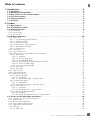
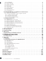
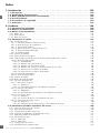
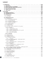
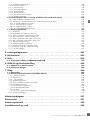
Table of contents
1. Introduction ...................................................5
1.1. Description ............................................................. 5
1.2. Validity of documentation ................................................. 5
1.3. Who should use this documentation .......................................... 5
1.4. Use of the product ....................................................... 5
1.5. Safety precautions ....................................................... 5
1.7. Acronyms ............................................................. 6
2. Product ......................................................7
2.1. Main features .......................................................... 7
2.2. Identification number ..................................................... 7
2.3. Operating modes ........................................................ 8
2.3.1. SIO mode ....................................................................8
2.3.2. IO-Link mode .................................................................. 8
2.3.3. Process data ..................................................................9
2.4. Output Parameters ..................................................... 10
2.4.1. Sensor front .................................................................11
2.4.1.1. SSC (Switching Signal Channel) ................................................11
2.4.1.2. Switchpoint mode: ..........................................................11
2.4.1.3. Hysteresis Settings ..........................................................13
2.4.1.4. Dust alarm 1 and Dust alarm 2 .................................................13
2.4.1.5. Temperature alarm (TA) ....................................................... 13
2.4.1.6. External input .............................................................13
2.4.2. Input selector ................................................................. 13
2.4.3. Logic function block ............................................................13
2.4.4. Timer (Can be set individually for Out1 and Out2) .......................................15
2.4.4.1. Timer mode ...............................................................15
2.4.4.1.1. Disabled .............................................................15
2.4.4.1.2. Turn On delay (T-on) .....................................................15
2.4.4.1.3. Turn Off delay (T-off) .....................................................16
2.4.4.1.4. Turn ON and Turn Off delay (T-on and T-off) .....................................16
2.4.4.1.5. One shot leading edge ...................................................16
2.4.4.1.6. One shot trailing edge ....................................................17
2.4.4.2. Timer scale ...............................................................17
2.4.4.3. Timer Value ...............................................................17
2.4.5. Output Inverter ...............................................................17
2.4.6. Output stage mode ............................................................17
2.4.7. Application functions ...........................................................18
2.4.7.1. Speed and Length ..........................................................18
2.4.7.1.1. Conditions ............................................................18
2.4.7.1.2. Speed and Length – Setup procedure ..........................................18
2.4.7.2. Pattern Recognition .........................................................19
2.4.7.2.1. Conditions ......................................................19
2.4.7.2.2. Pattern recognition – Setup procedure .........................................19
2.4.7.3. Divider function ............................................................21
2.4.7.3.1. Conditions ............................................................21
2.4.7.3.2. Divider function – Setup procedure ...........................................21
2.4.7.4. Object and Gap Monitoring ...................................................22
2.4.7.4.1. Conditions ............................................................22
2.4.7.4.2. Object and Gap Monitoring – Setup procedure ..................................22
2.5. Sensor Specific adjustable parameters ....................................... 24
2.5.1. Selection of local or remote adjustment ...............................................24
2.5.2. Trimmer data .................................................................24
2.5.3. Process data configuration .......................................................24
2.5.4. Sensor Measurement Selection ....................................................24
2.5.5. Temperature alarm threshold ......................................................24
2.5.6. Safe limits ...................................................................24
2.5.6.1. Stable ON ...............................................................24
ENGLISH

Rev.00 - 06.2021 | MAN PD30ETB IO-Link EN | © 2021 | CARLO GAVAZZI Industr6
4
EN
2.5.6.2. Stable OFF ............................................................... 24
2.5.7. Event configuration ............................................................25
2.5.8. Quality of run QoR ............................................................25
2.5.9. Quality of Teach QoT ...........................................................26
2.5.10. Excess Gain ................................................................26
2.5.11. Filter Scaler ................................................................. 26
2.5.12. Mutual interference ...........................................................26
2.5.13. LED indication ...............................................................27
2.5.14. Hysteresis mode .............................................................27
2.5.15. Auto hysteresis value ..........................................................27
2.5.16. Cutoff distance ..............................................................27
2.6. Teach procedure by use of SCTL55 or an IO-Link master .......................... 28
2.6.1. External Teach (Teach-by-wire) .....................................................28
2.6.2. Teach from IO-Link Master or Smart configurator (SCTL55) .................................28
2.6.2.1. Single point mode procedure ..................................................28
2.6.2.2. Two point mode procedure ....................................................30
2.6.2.3. Windows mode procedure ....................................................31
2.6.2.4. Foreground suppression mode ..................................................32
2.7. Diagnostic parameters ................................................... 33
2.7.1. Operating hours ..............................................................33
2.7.2. Number of power cycles [cycles] ...................................................33
2.7.3. Maximum temperature – all time high [°C] ............................................33
2.7.4. Minimum temperature – all time low [°C] .............................................33
2.7.5. Maximum temperature since last power-up [°C] .........................................33
2.7.6. Minimum temperature since last power-up [°C] .........................................33
2.7.7. Current temperature [°C] ........................................................33
2.7.8. Detection counter [cycles] ........................................................33
2.7.9. Minutes above maximum temperature [min] ...........................................33
2.7.10. Minutes below minimum temperature [min] ...........................................33
2.7.11. Download counter ............................................................33
3. Wiring diagrams ..............................................34
4. Commissioning . . . . . . . . . . . . . . . . . . . . . . . . . . . . . . . . . . . . . . . . . . . . . . . .34
5. Operation ...................................................35
5.1. User interface of PD30ETBxxxBPxxIO ....................................... 35
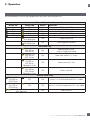
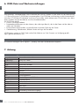
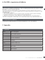
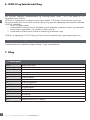
6. IODD file and factory setting .....................................36
6.1. IODD file of an IO-Link device ............................................. 36
6.2. Factory settings ........................................................ 36
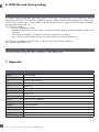
7. Appendix ....................................................36
7.1. Acronyms ............................................................ 36
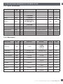
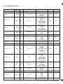
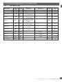
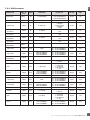
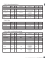
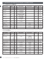
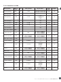
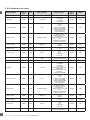
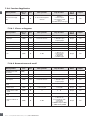
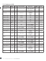
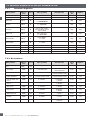
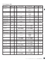
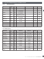
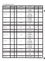
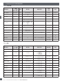
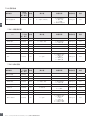
7.2. IO-Link Device Parameters for PD30ETB IO-Link ................................ 37
7.2.1. Device Identification ............................................................ 37
7.2.2. Observation .................................................................37
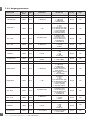
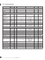
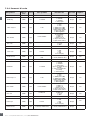
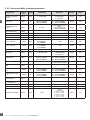
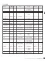
7.2.3. SSC parameters ..............................................................38
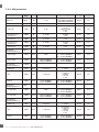
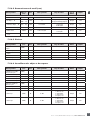
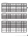
7.2.4. Output Parameters .............................................................39
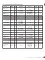
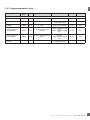
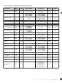
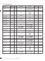
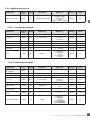
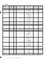
7.2.5. Sensor specific adjustable parameters ...............................................40
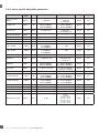
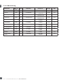
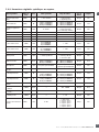
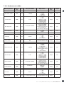
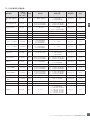
7.2.6. Application Function ...........................................................41
7.2.6.1. Speed and Length ..........................................................41
7.2.6.2. Pattern Recognition .........................................................41
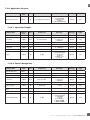
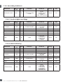
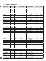
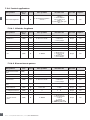
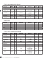
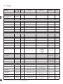
7.2.6.3. Divider ..................................................................42
7.2.6.4. Object and Gap Monitoring ...................................................42
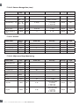
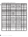
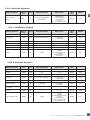
7.2.7. Diagnostic parameters ..........................................................43
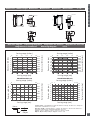
Dimensions ....................................................291
Detection diagram. . . . . . . . . . . . . . . . . . . . . . . . . . . . . . . . . . . . . . . . . . . . . . .291
Sensing Condition ...............................................292
Installation Hints ................................................293

Rev.00 - 06 .2021 | MAN PD30ETB IO-Link EN | © 2021 | CARLO GAVAZZI Industri
5
EN
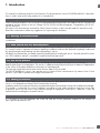
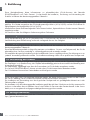
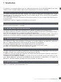
1. Introduction
This manual is a reference guide for Carlo Gavazzi IO-Link photoelectric sensors PD30ETBxxxBPxxIO. It describes
how to install, setup and use the product for its intended use.
1.2. Validity of documentation
This manual is valid only for PD30ETBxxxBPxxIO photoelectric sensors with IO-Link and until new documentation
is published.
1.3. Who should use this documentation
This instruction manual describes the function, operation and installation of the product for its intended use.
This manual contains important information regarding installation and must be read and completely understood
by specialized personnel dealing with these photoelectric sensors.
We highly recommend that you read the manual carefully before installing the sensor. Save the manual for future
use. The Installation manual is intended for qualified technical personnel.
1.4. Use of the product
These photoelectric diffuse reflective sensors are designed with Background Suppression, meaning it is
detecting the object via triangulation. The reciver is a detector array that performs precise detection independent
of the colour of the object and allows elimination of a background.
The received signal level can be read via the Process data in IO-Link mode.
The PD30ETBxxxBPxxIO sensors can operate with or without IO-Link communication. By means of an IO-Link
master it is possible to operate and configure these devices.
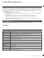
1.6. Other documents
It is possible to find the datasheet, the IODD file and the IO-Link parameter manual on the Internet at
http://gavazziautomation.com
1.5. Safety precautions
This sensor must not be used in applications where personal safety depends on the function of the sensor (The
sensor is not designed according to the EU Machinery Directive).
Installation and use must be carried out by trained technical personnel with basic electrical installation knowledge.
The installer is responsible for correct installation according to local safety regulations and must ensure that
a defective sensor will not result in any hazard to people or equipment. If the sensor is defective, it must be
replaced and secured against unauthorised use.
1.1. Description
Carlo Gavazzi photoelectric sensors are devices designed and manufactured in accordance with IEC international
standards and are subject to the Low Voltage (2014/35/EU) and Electromagnetic Compatibility (2014/30/
EU) EC directives.
All rights to this document are reserved by Carlo Gavazzi Industri, copies may be made for internal use only.
Please do not hesitate to make any suggestions for improving this document.

Rev.00 - 06.2021 | MAN PD30ETB IO-Link EN | © 2021 | CARLO GAVAZZI Industr6
6
EN
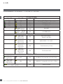
1.7. Acronyms
I/O Input/Output
PD Process Data
PLC Programmable Logic Controller
SIO Standard Input Output
SP Setpoints
IODD I/O Device Description
IEC International Electrotechnical Commission
NO Normally Open contact
NC Normally Closed contact
NPN Pull load to ground
PNP Pull load to V+
Push-Pull Pull load to ground or V+
QoR Quality of Run
QoT Quality of Teach
UART Universal Asynchronous Receiver-Transmitter
SO Switching Output
SSC Switching Signal Channel
DA Dust alarm
AFO Application function output
TA Temperatur alarm
BGS Background Suppression
FGS Foreground Suppression

Rev.00 - 06 .2021 | MAN PD30ETB IO-Link EN | © 2021 | CARLO GAVAZZI Industri
7
EN
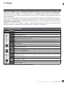
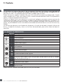
2. Product
2.1. Main features
IO-Link Carlo Gavazzi 4-wire DC photoelectric Background Suppression sensors, built to the highest quality
standards, is available in Stainless Steel housing AISI316L for harsh environment. IP69K and ECOLAB approved.
They can operate in standard I/O mode (SIO), which is the default operation mode. When connected to
an SCTL55 or an IO-Link master, they automatically switch to IO-Link mode and can be operated and easily
configured remotely.
Thanks to their IO-Link interface, these devices are much more intelligent and feature many additional configuration
options, such as the settable sensing distance and hysteresis, also timer functions of the output. Advanced
functionalities such as the Logic function block and the possibility to convert one output into an external input
makes the sensor highly flexible.
Application functions such as; Pattern recognition, Speed and Length monitoring, Divider function and Object
and Gap detection are de-central functions dedicated to solve specific sensing tasks.
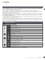
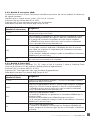
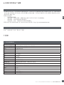
2.2. Identification number
Additional characters can be used for customized versions.
Code Option Description
P-Photoelectric Sensor
D-Rectangular housing
30 -Housing size
E-Stainless Steel housing - AISI316L
T-Top trimmer
B-Background Suppression
IInfrared light
RRed light
SPointSpot light source
20 200 mm sensing distance
25 250 mm sensing distance
35 350 mm sensing distance
B-Selectable functions: NPN, PNP, Push-Pull, External Input (only pin 2), External teach
input (only pin 2)
P-Selectable: NO or NC
A2 2 metre PVC cable
M5 M8, 4-pole connector
IO -IO-Link version

Rev.00 - 06.2021 | MAN PD30ETB IO-Link EN | © 2021 | CARLO GAVAZZI Industr6
8
EN
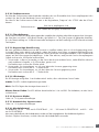
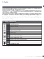
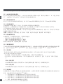
2.3. Operating modes
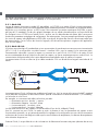
IO-Link photoelectric sensors are provided with two switching outputs (SO) and can operate in two different
modes: SIO mode (standard I/O mode) or IO-Link mode (pin 4).
2.3.1. SIO mode
When the sensor operates in SIO mode (default), a SCTL55 or an O-Link master is not required. The device
works as a standard photoelectric sensor, and it can be operated via a fieldbus device or a controller (e.g. a
PLC) when connected to its PNP, NPN or push-pull digital inputs (standard I/O port). One of the greatest benefits
of these photoelectric sensors is the possibility to configure them via a SCTL55 or an O-Link master and then,
once disconnected from the master, they will keep the last parameter and configuration settings. In this way
it is possible, for example, to configure the outputs of the sensor individually as a PNP, NPN or push-pull, or
to add timer functions such as T-on and T-off delays or logic functions and thereby satisfy several application
requirements with the same sensor.
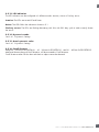
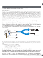
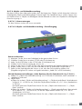
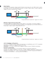
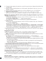
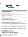
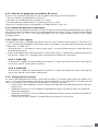
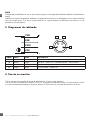
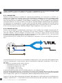
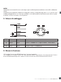
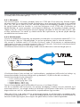
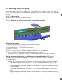
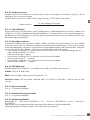
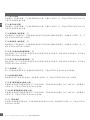
2.3.2. IO-Link mode
IO-Link is a standardized IO technology that is recognized worldwide as an international standard (IEC 61131-9).
It is today considered to be the “USB interface” for sensors and actuators in the industrial automation environment.
When the sensor is connected to one IO-Link port, the SCTL55 or IO-Link master sends a wakeup request (wake up
pulse) to the sensor, which automatically switches to IO-Link mode: point-to-point bidirectional communication then
starts automatically between the master and the sensor.
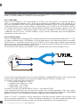
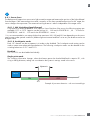
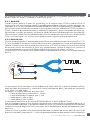
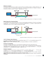
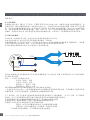
IO-Link communication requires only standard 3-wire unshielded cable with a maximum length of 20 m.
1
2 4
3
L+
C/Q
L-
IO-Link
SIO
IO-Link communication takes place with a 24 V pulse modulation, standard UART protocol via the switching and
communication cable (combined switching status and data channel C/Q) PIN 4 or black wire.
For instance, an M8 4-pin male connector has:
• Positive power supply: pin 1, brown
• Negative power supply: pin 3, blue
• Digital output 1: pin 4, black
• Digital output 2: pin 2, white
The transmission rate of PD30ETBxxxBPxxIO sensors is 38.4 kBaud (COM2).
Once connected to the IO-Link port, the master has remote access to all the parameters of the sensor and to
advanced functionalities, allowing the settings and configuration to be changed during operation, and enabling
diagnostic functions, such as temperature warnings, temperature alarms and process data.
Thanks to IO-Link it is possible to see the manufacturer information and part number (Service Data) of the
device connected, starting from V1.1. Thanks to the data storage feature it is possible to replace the device and
automatically have all the information stored in the old device transferred into the replacement unit.

Rev.00 - 06 .2021 | MAN PD30ETB IO-Link EN | © 2021 | CARLO GAVAZZI Industri
9
EN
Access to internal parameters allows the user to see how the sensor is performing, for example by reading the
internal temperature.
Event Data allows the user to get diagnostic information such as an error, an alarm, a warning or a communication
problem.
There are two different communication types between the sensor and the master and they are independent of
each other:
• Cyclical for process data and value status – this data is exchanged cyclically.
• Acyclical for parameter configuration, identification data, diagnostic information and events
(e.g. error messages or warnings) – this data can be exchanged on request.
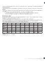
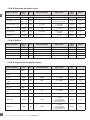
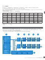
2.3.3. Process data
By default the process data shows the following parameters as active: 16 bit Analogue value, Switching
Output1 (SO1) and Switching Output 2 (SO2).
The following parameters are set as Inactive: SSC1, SSC2, TA, SC, DA1, DA2, AFO1.
However by changing the Process Data Configuration parameter, the user can decide to also enable the status
of the inactive parameters. This way several states can be observed in the sensor at the same time.
Process data can be configured. See 2.5.3. Process data configuration.
Byte 0 31 30 29 28 27 26 25 24
MSB
Byte 1 23 22 21 20 19 18 17 16
LSB
Byte 2 15 14 13 12 11 10 9 8
SC TA DA2 DA1 SSC2 SSC1
Byte 3 76543210
AFO1 SO2 SO1
4 Bytes
Analogue value 16 … 31 (16 BIT)

Rev.00 - 06.2021 | MAN PD30ETB IO-Link EN | © 2021 | CARLO GAVAZZI Industr6
10
EN
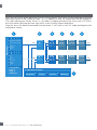
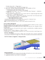
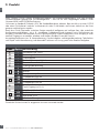
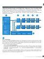
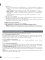
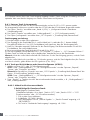
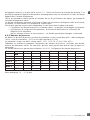
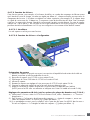
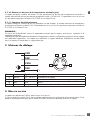
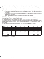
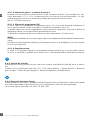
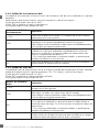
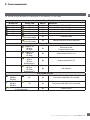
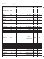
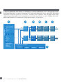
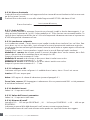
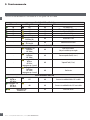
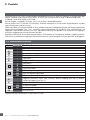
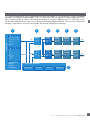
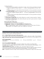
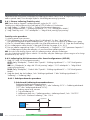
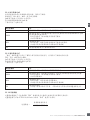
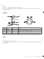
2.4. Output Parameters
Seven sensing functions and 4 application functions can be selected. These values can be independently adjusted
and used as source for the Switching Output 1 or 2; in addition to those, an external input can be selected for
SO2. After selecting one of these sources, it is possible to configure the output of the sensor with a SCTL55 or
an IO-Link master, following the seven steps shown in the Switching Output setup below.
Once the sensor has been disconnected from the master, it will switch to the SIO mode and keep the last
configuration setting.
S.P.1 (trimmer/IO-Link)
S.P.2
Hysteresis (man./auto)
Logic
Single point
Two point
Windows
FGS
S.P.1
S.P.2
Hysteresis
Logic
Single point
Two point
Windows
FGS
3. Temperature
4. Dust 1
5. Dust 2
6. EXT-Input
Selector
ALogic
A - B Time
delay Output
inverter Sensor
output
One of
1 to 7 AND, OR,
XOR, S-R ON, OFF
One-shot N.O., N.C. NPN, PNP,
Push-Pull
Selector
BLogic
A - B Time
delay Output
inverter Sensor
output
One of
1 to 7 AND, OR,
XOR, S-R ON, OFF
One-shot N.O., N.C. NPN, PNP,
Push-Pull
EXT-Input
A
B
A
B
SO1
SO2
EXT-
Input
1. SSC1
2. SSC2
Sensor front
SSC1
SSC2
Pattern
Recognition Object & Gap
Monitoring
Speed &
Length Divider
function
or or
or
7. Aplication functions
1 2 3 4 5
7
6

Rev.00 - 06 .2021 | MAN PD30ETB IO-Link EN | © 2021 | CARLO GAVAZZI Industri
11
EN
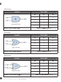
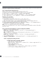
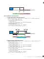
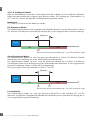
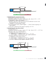
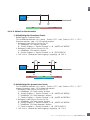
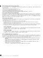
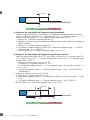
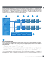
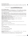
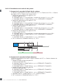
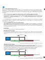
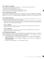
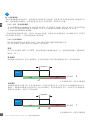
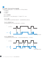
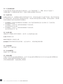
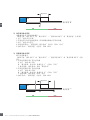
2.4.1.2. Switchpoint mode:
Each SSC channel can be set operate in 4 modes or be disabled. The Switchpoint mode setting can be
used to create more advanced output behaviour. The following switchpoint modes can be selected for the
switching behaviour of SSC1 and SSC2
Disabled
SSC1 or SSC2 can be disabled individually.
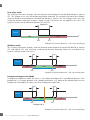
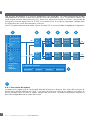
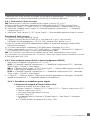
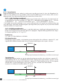
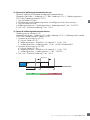
Single point mode
The switching information changes, when the distance passes the threshold defined in setpoint SP1, with
rising or falling distances, taking into consideration the hysteresis settings stored in the sensor.
Sensor
Sensing distance
ON OFF
SP1
Hysteresis
Example of presence detection - with non-inverted logic
2.4.1. Sensor front
The Background Suppression sensor emits light towards a target and measure the position of the light reflected
from the target. If the measured position value is equal to or less than a predefined position for the target, the
sensor changes the output state. The measured sensing distance is almost independent of the target colour.
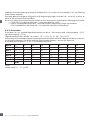
2.4.1.1. SSC (Switching Signal Channel)
For presence (or absence) detection of an object in front of the face of the sensor, the following settings are
available: SSC1 or SSC2. Setpoints can be set from 20 ... 225 mm for PD30ETB.20..., 20 ... 275 mm for
PD30ETBS25... and 20 ... 375 mm for the PD30ETBR35... sensor *.
1
* It is not recommended to use settings higher than maximum 200, 250 and 350 mm depending on the sensor
type however under optimal conditions (ambient light environment and EMC noise etc.) the distance can be set
at higher value.

Rev.00 - 06.2021 | MAN PD30ETB IO-Link EN | © 2021 | CARLO GAVAZZI Industr6
12
EN
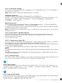
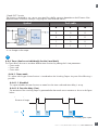
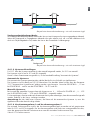
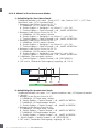
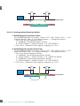
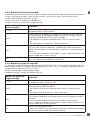
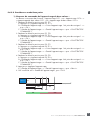
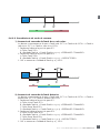
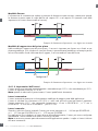
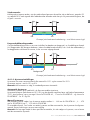
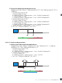
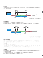
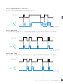
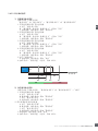
Window mode
The switching information changes, when the distance measured passes the thresholds defined in setpoint
SP1 and setpoint SP2, with increasing or decreasing distance measured, taking into consideration the
hysteresis settings stored in the sensor.
Sensor
Sensing distance
SP2
Hyst
OFF OFF
ON
SP1
Hyst
window
Example of presence detection - with non-inverted logic
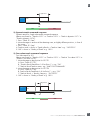
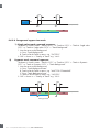
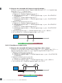
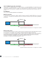
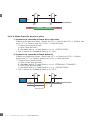
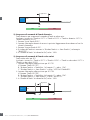
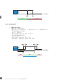
Two point mode
The switching information changes when the distance measured passes the threshold defined in setpoint
SP1. This change occurs only with decreasing distance measured. The switching information also changes
when the distance measured passes the threshold defined in setpoint SP2. This change occurs only with
increasing distance measured. Hysteresis settings stored in the sensor are not applied in this case. The
hysteresis results from the difference between SP1 and SP2.
Sensor
Sensing distance
ON OFF
SP2
Hysteresis
SP1
Example of presence detection - with non-inverted logic
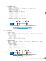
Sensor
Sensing distance
SP2
Hyst
ON ON
OFF
SP1
Hyst
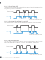
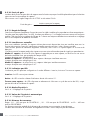
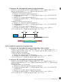
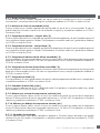
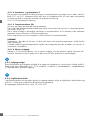
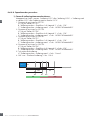
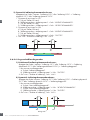
FGS
Background
Foreground suppression Mode
In foreground suppression mode, the sensor is set to detect a background in a predefined distance. If the
background is no longer detected in this predefined distance, e.g. because the reflected light from the
background is blocked by an object, the sensor changes the output state.
Example of presence detection - with non-inverted logic

Rev.00 - 06 .2021 | MAN PD30ETB IO-Link EN | © 2021 | CARLO GAVAZZI Industri
13
EN
2
2.4.2. Input selector
This function block allows the user to select any of the signals from the “sensor front” to the Channel A or B.
Channels A and B: can select from SSC1, SSC2, Dust alarm 1, Dust alarm 2, Water drop alarm 1, Water drop
alarm 2, Temperature alarm and External input.
3
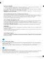
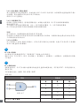
2.4.3. Logic function block
In the logic function block a logic function can be added directly to the selected signals from the input selector
without using a PLC – making decentralised decisions possible.
The logic functions available are: AND, OR, XOR, SR-FF.
2.4.1.6. External input
The output 2 (SO2) can be configured as an external input allowing external signals to be fed into the
sensor, e.g. from a second sensor or from a PLC or directly from machine output.
2.4.1.4. Dust alarm 1 and Dust alarm 2
Minimum Excess Gain is used for dust alarm levels and is set as a common value for both SSC1
and SSC2. The dust alarm will be active after a preset time, if the measured Excess Gain value is
below the Minimum Excess gain.
See 2.5.10 Excess Gain.
2.4.1.5. Temperature alarm (TA)
The sensor monitors constantly the internal temperature. Using the temperature alarm setting it is possible to
get an alarm from the sensor if temperature thresholds are exceeded. See §2.5.5.
Two independent temperature alarm settings can be set. One for the maximum temperature alarm and one
for the minimum temperature alarm.
It is possible to read the temperature of the sensor via the acyclic IO-Link parameter data.
NOTE!
The temperature measured by the sensor will always be higher than the ambient temperature, due to internal
heating.
The difference between ambient temperature and internal temperature is influenced by how the sensor is
installed in the application.
2.4.1.3. Hysteresis Settings
The hysteresis can be set automatically or manually for SSC1 and manually only for SSC2. The hysteresis is
set in mm for SP1 and SP2.
Note: When trimmer is selected, the default hysteresis is Automatic.
Automatic hysteresis:
Automatic hysteresis will guarantee stable operation for most applications.
Hysteresis is calculated with reference to SP1/SP2 and the actual values can be read via parameter “SSC1
Auto hysteresis”, typically 14 mm for PD30ETB.20.., 17 mm for PD30ETBS25... and 24 mm for
PD30ETBR35... for SP1 and SP2.
Manual hysteresis:
When manual hysteresis is selected the hysteresis can be changed between 2 ... 225 mm for PD30ETB.20...,
2 ... 275 mm for PD30ETBS25 and 2 ... 375 mm for PD30ETBR...
For application that require a hysteresis other than the automatic, the hysteresis can be configured manually.
This feature makes the sensor more versatile.
Note: Special attention to the application must be considered when choosing a hysteresis lower than the
automatic hysteresis.

Rev.00 - 06.2021 | MAN PD30ETB IO-Link EN | © 2021 | CARLO GAVAZZI Industr6
14
EN
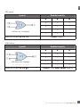
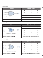
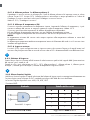
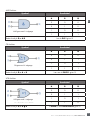
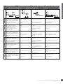
OR function
Symbol Truth table
A B Q
0 0 0
0 1 1
1 0 1
1 1 1
Boolean Expression Q = A + B Read as A OR B gives Q
2-input OR Gate
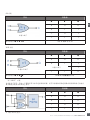
XOR function
Symbol Truth table
A B Q
0 0 0
0 1 1
1 0 1
1 1 0
Boolean Expression Q = A + B A OR B but NOT BOTH gives Q
2-input XOR Gate
+
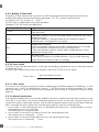
AND function
Symbol Truth table
A B Q
0 0 0
0 1 0
1 0 0
1 1 1
Boolean Expression Q = A.B Read as A AND B gives Q
2-input AND Gate

Rev.00 - 06 .2021 | MAN PD30ETB IO-Link EN | © 2021 | CARLO GAVAZZI Industri
15
EN
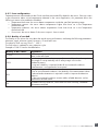
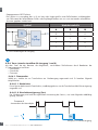
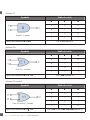
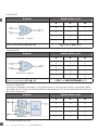
“Gated SR-FF” function
The function is designed to: e.g. start or stop signal for a buffer conveyor dependent on the fill status of the
adjacent feeder or receiver conveyor using only two interconnected sensors.
Symbol Truth table
A B Q
0 0 0
0 1 X
1 0 X
1 1 1
X – no changes to the output.
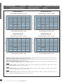
2.4.4. Timer (Can be set individually for Out1 and Out2)
The Timer allows the user to introduce different timer functions by editing the 3 timer parameters:
• Timer mode
• Timer scale
• Timer value
4
2.4.4.1. Timer mode
This selects which type of timer function is introduced on the Switching Output. Any one of the following is
possible:
2.4.4.1.1. Disabled
This option disables the timer function no matter how the timer scale and timer delay is set up.
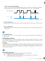
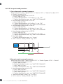
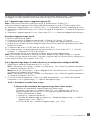
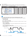
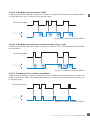
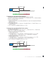
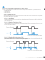
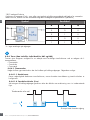
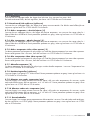
2.4.4.1.2. Turn On delay (T-on)
The activation of the switching output is generated after the actual sensor actuation as shown in the figure
below.
Presence of
target
N.O. Ton Ton Ton
Presence of target
Example with normally open output

Rev.00 - 06.2021 | MAN PD30ETB IO-Link EN | © 2021 | CARLO GAVAZZI Industr6
16
EN
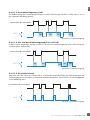
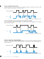
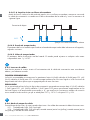
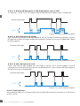
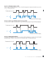
2.4.4.1.5. One shot leading edge
Each time a target is detected in front of the sensor the switching output generates a pulse of constant
length on the leading edge of the detection. This function is not retriggerable. See figure below.
N.O. ∆t ∆t ∆t∆t
Presence of target
Example with normally open output
Example with normally open output
2.4.4.1.3. Turn Off delay (T-off)
The deactivation of the switching output is delayed until after to the time of removal of the target in the front
of the sensor, as like shown in the figure below.
Presence of
target
N.O. Toff Toff Toff Toff
Presence of target
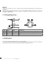
2.4.4.1.4. Turn ON and Turn Off delay (T-on and T-off)
When selected, both the Ton and the Toff delays are applied to the generation of the switching output.
N.O. Ton Ton Ton
Toff Toff
Presence of target
Example with normally open output

Rev.00 - 06 .2021 | MAN PD30ETB IO-Link EN | © 2021 | CARLO GAVAZZI Industri
17
EN
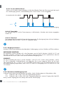
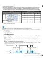
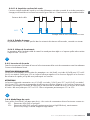
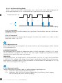
2.4.4.1.6. One shot trailing edge
Similar in function to the one shot leading edge mode, but in this mode the switching output is changed on
the trailing edge of the activation as shown in the figure below. This function is not retriggerable.
N.O. ∆t ∆t ∆t∆t
Presence of target
Example with normally open output
2.4.4.2. Timer scale
The parameter defines if the delay specified in the Timer delay should be in milliseconds, seconds or minutes
2.4.4.3. Timer Value
The parameter defines the actual duration of the delay. The delay can be set to any integer value between
1 and 32 767.
2.4.5. Output Inverter
This function allows the user to invert the operation of the switching output between Normally Open and
Normally Closed.
5
RECOMMENDED FUNCTION
The recommended function is found in the parameters under 64 (0x40) sub index 8 (0x08) for SO1 and 65
(0x41) sub index 8 (0x08) for SO2. It has no negative influence on the Logic functions or the timer functions of
the sensor as it is added after those functions.
CAUTION!
The Switching logic function found under 61 (0x3D) sub index 1 (0x01) for SSC1 and 63 (0x3F) sub index
1 (0x01) for SSC2 are not recommended for use as they will have a negative influence on the logic or timer
functions. Using this function will turn an ON delay into an Off delay if it is added for the SSC1 and SSC2. It
is only for the SO1 and SO2.
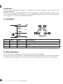
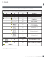
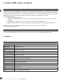
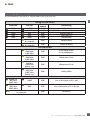
2.4.6. Output stage mode
In this function block the user can select if the switching outputs should operate as:
SO1: Disabled, NPN, PNP or Push-Pull configuration.
SO2: Disabled, NPN, PNP, Push-Pull , External input (Active high/Pull-down), External input
(Active low/pull up) or External Teach input.
6

Rev.00 - 06.2021 | MAN PD30ETB IO-Link EN | © 2021 | CARLO GAVAZZI Industr6
18
EN
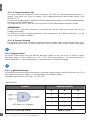
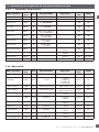
2.4.7. Application functions
4 unique application functions can be selected via IO-Link only.
• Speed and Length.
• Pattern Recognition.
• Divider.
• Object and Gap Monitoring.
All application functions are disabled as factory setting.
7
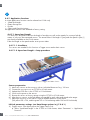
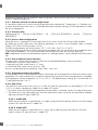
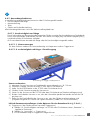
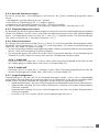
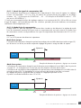
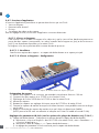
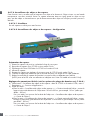
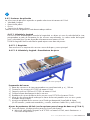
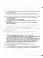
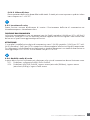
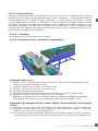
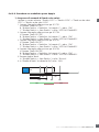
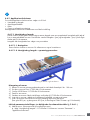
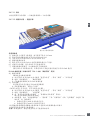
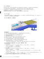
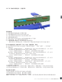
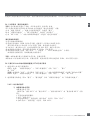
2.4.7.1. Speed and Length
This function is designed to monitor the length of an object as well as the speed of a conveyor belt by
means of only two interconnected sensors. The actual value if the length in [mm] and the speed in [mm/s]
are directly available on the IO-Link master.
Either the length or the speed can be set as process data.
2.4.7.1.1. Conditions
Two sensors are needed for this function: a Trigger sensor and a Main sensor.
2.4.7.1.2. Speed and Length – Setup procedure
Sensor preparation
1) Mount two sensors at the conveyor with an individual distance of e.g. 100 mm
2) Connect the two sensors to an SCTL55 or IO-Link master
3) Upload the IODD files in the SCTL55 or IO-Link Master
4) Switch on the power to the sensors
5) Restore the sensors to factory settings using the SCTL55 or IO-Link master.
6) Align the two sensors so the light beams are parallel to each other and aimed at the target.
7) Adjust the sensitivity on the sensors to get a reliable detection on the object.
(The yellow LED is ON, and the green LED is ON indicating stable ON and IO-Link Mode)
IO-Link parameter settings (see Data Range options in § 7.2.6.1.)
8) Trigger sensor: (The object passes the Trigger Sensor first)
a) Select “Speed and Length” in the SCTL55 or IO-Link master; Menu “Parameter” -> “Application
Functions”
Alignment of Trigger and Main Sensor

Rev.00 - 06 .2021 | MAN PD30ETB IO-Link EN | © 2021 | CARLO GAVAZZI Industri
19
EN
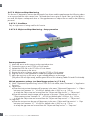
b) Select “Sensor role” -> “Trigger Sensor”
c) IO-Link Parameter Set-up is finished for the Trigger Sensor
9) Main sensor: (calculates Speed and Length and makes data available via IO-Link)
a) Reset the sensor using “Restore factory Settings”
(if already performed in point 5 then this can be skipped).
b) Select “Speed and Length” in the SCTL55 or IO-Link master; Menu “Parameter” -> “Application
Functions”
c) Select “Sensor role” -> “Main Sensor”.
d) Enter the distance in between the two sensors in [mm] in the menu “Speed and Length Measurement
Main Sensor” -> “Distance between sensors”
e) Select “Object Length” or “Object Speed” if required in “Process Data” in the “Observation menu”
under “Process data configuration” -> “Analogue value”
i. Object Length will be shown in [mm]
ii. Object Speed will be shown in [mm/s]
10) Connect sensor output Pin 2 of the Trigger Sensor to Input Pin 2 of the Main Sensor
11) The Speed and length function is now ready for use.
NB! During the measurement variations in the conveyor speed may impact the result.
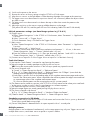
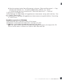
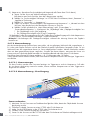
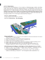
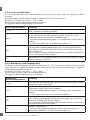
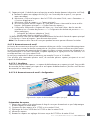
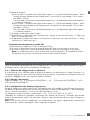
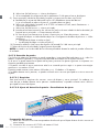
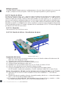
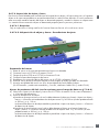
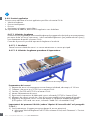
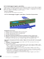
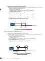
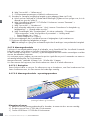
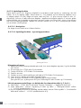
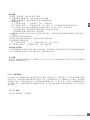
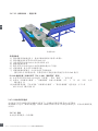
2.4.7.2. Pattern Recognition
The pattern recognition function is used to verify if a manufactured part has all the e.g. holes or taps as
expected and that the parts are made according to the specification.
A pattern of a part can be recorded into the sensor and the following parts then compared to the pre-
recorded pattern.
If pattern match, the sensor will respond with a positive signal or command either as standalone operation
or via an IO-Link master
The pattern can max. contain 20 edges eg. 10 holes or 10 taps.
If multiple pattern are to be detected then several Main sensors can be connected to a single Trigger sensor.
2.4.7.2.1. Conditions
Two sensors are needed for this function a Trigger Sensor and a Main Sensor, however several Main
sensors can be connected to the Trigger Sensor if more than one pattern must be examined simultaneously.
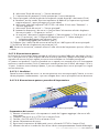
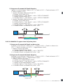
2.4.7.2.2. Pattern recognition – Setup procedure
Sensor preparation
1) Mount two sensors at the conveyor in line so the object will reach the two sensors at the same time.
2) Connect the two sensors to an SCTL55 or IO-Link master
3) Upload the IODD files in the SCTL55 or IO-Link Master
Alignment of Trigger and Main Sensor

Rev.00 - 06.2021 | MAN PD30ETB IO-Link EN | © 2021 | CARLO GAVAZZI Industr6
20
EN
4) Switch on the power to the sensors
5) Restore the sensors to factory settings using the SCTL55 or IO-Link master.
6) Align the two sensors so the light beams will be detecting the edge of the target at the same time.
7) The trigger sensor must be mounted in a position where it will continuously detect the object without
any holes or taps.
8) The Main sensor must be mounted so it detects the taps or holes that contain the pattern to be
examined
9) Adjust the sensitivity on the sensors to get a reliable detection on the target.
(The yellow LED are ON, and the green LED are ON indicating Stable ON and IO-Link Mode)
IO-Link parameter settings (see Data Range options in § 7.2.6.2.)
10) Trigger sensor:
a) Select “Pattern Recognition” in the SCTL55 or IO-Link master; Menu “Parameter” -> “Application
Functions”
b) Select “Sensor role” -> “Trigger Sensor”
c) IO-Link Parameter Set-up is finished for the Trigger Sensor
11) Main sensor:
a) Select “Pattern Recognition” in the SCTL55 or IO-Link master; Menu “Parameter” -> “Application
Functions”
b) Select “Sensor role” -> “Main Sensor”.
c) Enter the Timeout value used for maximum evaluation time between 1 … 60 sec, in the menu
“Pattern Recognition Setup” -> “Timeout” (default value is 60 sec.)
d) Enter the Tolerance of the Pattern in ‰ (Parts per thousand), between 1 and 200 ‰ in the menu
“Pattern Recognition Setup” -> “Tolerance”, default value is 50 ‰
12) Connect sensor output Pin 2 of the Trigger Sensor to Input Pin 2 of the Main Sensor(s)
Teach the Pattern
13) Activate the “Teach Pattern” command to start learning the pattern
14) Move the target at a steady speed passing fully by the two sensors
NB! During the measurement variations in the conveyor speed may impact the result.
15) The sensor responds with:
a) “Saved” in “Pattern Recognition Result” -> “Reference Pattern”
b) “E.g. 12” in “Pattern Recognition Result” -> “Reference Pattern No Of Edges” (counts both the
leading and trailing edges of the measurement targets).
c) Each edge is saved in ms from the leading edge of the complete measurement target and can be
found in the Observation menu. When compared to the reference pattern the edges are normalized
as a percentage value of the complete measurement target.
This ensures that the pattern can be recognized at various constant speeds.
16) The Pattern can be saved as a project in the SCTL55 or IO-Link master and at a later point send back
to the sensor in order to use this specific saved pattern as a reference pattern.
17) The Pattern Recognition function is now ready for use.
18) Move the target again at a steady speed passing fully by the two sensors
19) The Sensor responds with the text
a) “E.g. 12” in “Pattern Recognition Result” -> “Number of Edges Last Pattern”
20) “Patterns Match” in “Pattern Recognition Result” -> “Pattern Recognition Status”
Standalone operation in SIO Mode
21) Disconnect the sensor from the SCTL55 or IO-Link master and connect the Pin 4 to your e.g. decentral
Tower light or good/bad conveyor belt
22) Once a valid pattern is detected the Pin 4 output responds with a 1 second pulse.
Multiple patterns
Multiple patterns can be detected simultaneously on the same target using only one Trigger sensor and
multiple Main sensors, each Main sensor responds to a specific Pattern.
Seite wird geladen ...
Seite wird geladen ...
Seite wird geladen ...
Seite wird geladen ...
Seite wird geladen ...
Seite wird geladen ...
Seite wird geladen ...
Seite wird geladen ...
Seite wird geladen ...
Seite wird geladen ...
Seite wird geladen ...
Seite wird geladen ...
Seite wird geladen ...
Seite wird geladen ...
Seite wird geladen ...
Seite wird geladen ...
Seite wird geladen ...
Seite wird geladen ...
Seite wird geladen ...
Seite wird geladen ...
Seite wird geladen ...
Seite wird geladen ...
Seite wird geladen ...
Seite wird geladen ...
Seite wird geladen ...
Seite wird geladen ...
Seite wird geladen ...
Seite wird geladen ...
Seite wird geladen ...
Seite wird geladen ...
Seite wird geladen ...
Seite wird geladen ...
Seite wird geladen ...
Seite wird geladen ...
Seite wird geladen ...
Seite wird geladen ...
Seite wird geladen ...
Seite wird geladen ...
Seite wird geladen ...
Seite wird geladen ...
Seite wird geladen ...
Seite wird geladen ...
Seite wird geladen ...
Seite wird geladen ...
Seite wird geladen ...
Seite wird geladen ...
Seite wird geladen ...
Seite wird geladen ...
Seite wird geladen ...
Seite wird geladen ...
Seite wird geladen ...
Seite wird geladen ...
Seite wird geladen ...
Seite wird geladen ...
Seite wird geladen ...
Seite wird geladen ...
Seite wird geladen ...
Seite wird geladen ...
Seite wird geladen ...
Seite wird geladen ...
Seite wird geladen ...
Seite wird geladen ...
Seite wird geladen ...
Seite wird geladen ...
Seite wird geladen ...
Seite wird geladen ...
Seite wird geladen ...
Seite wird geladen ...
Seite wird geladen ...
Seite wird geladen ...
Seite wird geladen ...
Seite wird geladen ...
Seite wird geladen ...
Seite wird geladen ...
Seite wird geladen ...
Seite wird geladen ...
Seite wird geladen ...
Seite wird geladen ...
Seite wird geladen ...
Seite wird geladen ...
Seite wird geladen ...
Seite wird geladen ...
Seite wird geladen ...
Seite wird geladen ...
Seite wird geladen ...
Seite wird geladen ...
Seite wird geladen ...
Seite wird geladen ...
Seite wird geladen ...
Seite wird geladen ...
Seite wird geladen ...
Seite wird geladen ...
Seite wird geladen ...
Seite wird geladen ...
Seite wird geladen ...
Seite wird geladen ...
Seite wird geladen ...
Seite wird geladen ...
Seite wird geladen ...
Seite wird geladen ...
Seite wird geladen ...
Seite wird geladen ...
Seite wird geladen ...
Seite wird geladen ...
Seite wird geladen ...
Seite wird geladen ...
Seite wird geladen ...
Seite wird geladen ...
Seite wird geladen ...
Seite wird geladen ...
Seite wird geladen ...
Seite wird geladen ...
Seite wird geladen ...
Seite wird geladen ...
Seite wird geladen ...
Seite wird geladen ...
Seite wird geladen ...
Seite wird geladen ...
Seite wird geladen ...
Seite wird geladen ...
Seite wird geladen ...
Seite wird geladen ...
Seite wird geladen ...
Seite wird geladen ...
Seite wird geladen ...
Seite wird geladen ...
Seite wird geladen ...
Seite wird geladen ...
Seite wird geladen ...
Seite wird geladen ...
Seite wird geladen ...
Seite wird geladen ...
Seite wird geladen ...
Seite wird geladen ...
Seite wird geladen ...
Seite wird geladen ...
Seite wird geladen ...
Seite wird geladen ...
Seite wird geladen ...
Seite wird geladen ...
Seite wird geladen ...
Seite wird geladen ...
Seite wird geladen ...
Seite wird geladen ...
Seite wird geladen ...
Seite wird geladen ...
Seite wird geladen ...
Seite wird geladen ...
Seite wird geladen ...
Seite wird geladen ...
Seite wird geladen ...
Seite wird geladen ...
Seite wird geladen ...
Seite wird geladen ...
Seite wird geladen ...
Seite wird geladen ...
Seite wird geladen ...
Seite wird geladen ...
Seite wird geladen ...
Seite wird geladen ...
Seite wird geladen ...
Seite wird geladen ...
Seite wird geladen ...
Seite wird geladen ...
Seite wird geladen ...
Seite wird geladen ...
Seite wird geladen ...
Seite wird geladen ...
Seite wird geladen ...
Seite wird geladen ...
Seite wird geladen ...
Seite wird geladen ...
Seite wird geladen ...
Seite wird geladen ...
Seite wird geladen ...
Seite wird geladen ...
Seite wird geladen ...
Seite wird geladen ...
Seite wird geladen ...
Seite wird geladen ...
Seite wird geladen ...
Seite wird geladen ...
Seite wird geladen ...
Seite wird geladen ...
Seite wird geladen ...
Seite wird geladen ...
Seite wird geladen ...
Seite wird geladen ...
Seite wird geladen ...
Seite wird geladen ...
Seite wird geladen ...
Seite wird geladen ...
Seite wird geladen ...
Seite wird geladen ...
Seite wird geladen ...
Seite wird geladen ...
Seite wird geladen ...
Seite wird geladen ...
Seite wird geladen ...
Seite wird geladen ...
Seite wird geladen ...
Seite wird geladen ...
Seite wird geladen ...
Seite wird geladen ...
Seite wird geladen ...
Seite wird geladen ...
Seite wird geladen ...
Seite wird geladen ...
Seite wird geladen ...
Seite wird geladen ...
Seite wird geladen ...
Seite wird geladen ...
Seite wird geladen ...
Seite wird geladen ...
Seite wird geladen ...
Seite wird geladen ...
Seite wird geladen ...
Seite wird geladen ...
Seite wird geladen ...
Seite wird geladen ...
Seite wird geladen ...
Seite wird geladen ...
Seite wird geladen ...
Seite wird geladen ...
Seite wird geladen ...
Seite wird geladen ...
Seite wird geladen ...
Seite wird geladen ...
Seite wird geladen ...
Seite wird geladen ...
Seite wird geladen ...
Seite wird geladen ...
Seite wird geladen ...
Seite wird geladen ...
Seite wird geladen ...
Seite wird geladen ...
Seite wird geladen ...
Seite wird geladen ...
Seite wird geladen ...
Seite wird geladen ...
Seite wird geladen ...
Seite wird geladen ...
Seite wird geladen ...
Seite wird geladen ...
Seite wird geladen ...
Seite wird geladen ...
Seite wird geladen ...
Seite wird geladen ...
Seite wird geladen ...
Seite wird geladen ...
Seite wird geladen ...
Seite wird geladen ...
Seite wird geladen ...
Seite wird geladen ...
Seite wird geladen ...
Seite wird geladen ...
Seite wird geladen ...
Seite wird geladen ...
Seite wird geladen ...
Seite wird geladen ...
Seite wird geladen ...
Seite wird geladen ...
Seite wird geladen ...
Seite wird geladen ...
Seite wird geladen ...
Seite wird geladen ...
Seite wird geladen ...
Seite wird geladen ...
Seite wird geladen ...
Seite wird geladen ...
Seite wird geladen ...
Seite wird geladen ...
Seite wird geladen ...
Seite wird geladen ...
-
 1
1
-
 2
2
-
 3
3
-
 4
4
-
 5
5
-
 6
6
-
 7
7
-
 8
8
-
 9
9
-
 10
10
-
 11
11
-
 12
12
-
 13
13
-
 14
14
-
 15
15
-
 16
16
-
 17
17
-
 18
18
-
 19
19
-
 20
20
-
 21
21
-
 22
22
-
 23
23
-
 24
24
-
 25
25
-
 26
26
-
 27
27
-
 28
28
-
 29
29
-
 30
30
-
 31
31
-
 32
32
-
 33
33
-
 34
34
-
 35
35
-
 36
36
-
 37
37
-
 38
38
-
 39
39
-
 40
40
-
 41
41
-
 42
42
-
 43
43
-
 44
44
-
 45
45
-
 46
46
-
 47
47
-
 48
48
-
 49
49
-
 50
50
-
 51
51
-
 52
52
-
 53
53
-
 54
54
-
 55
55
-
 56
56
-
 57
57
-
 58
58
-
 59
59
-
 60
60
-
 61
61
-
 62
62
-
 63
63
-
 64
64
-
 65
65
-
 66
66
-
 67
67
-
 68
68
-
 69
69
-
 70
70
-
 71
71
-
 72
72
-
 73
73
-
 74
74
-
 75
75
-
 76
76
-
 77
77
-
 78
78
-
 79
79
-
 80
80
-
 81
81
-
 82
82
-
 83
83
-
 84
84
-
 85
85
-
 86
86
-
 87
87
-
 88
88
-
 89
89
-
 90
90
-
 91
91
-
 92
92
-
 93
93
-
 94
94
-
 95
95
-
 96
96
-
 97
97
-
 98
98
-
 99
99
-
 100
100
-
 101
101
-
 102
102
-
 103
103
-
 104
104
-
 105
105
-
 106
106
-
 107
107
-
 108
108
-
 109
109
-
 110
110
-
 111
111
-
 112
112
-
 113
113
-
 114
114
-
 115
115
-
 116
116
-
 117
117
-
 118
118
-
 119
119
-
 120
120
-
 121
121
-
 122
122
-
 123
123
-
 124
124
-
 125
125
-
 126
126
-
 127
127
-
 128
128
-
 129
129
-
 130
130
-
 131
131
-
 132
132
-
 133
133
-
 134
134
-
 135
135
-
 136
136
-
 137
137
-
 138
138
-
 139
139
-
 140
140
-
 141
141
-
 142
142
-
 143
143
-
 144
144
-
 145
145
-
 146
146
-
 147
147
-
 148
148
-
 149
149
-
 150
150
-
 151
151
-
 152
152
-
 153
153
-
 154
154
-
 155
155
-
 156
156
-
 157
157
-
 158
158
-
 159
159
-
 160
160
-
 161
161
-
 162
162
-
 163
163
-
 164
164
-
 165
165
-
 166
166
-
 167
167
-
 168
168
-
 169
169
-
 170
170
-
 171
171
-
 172
172
-
 173
173
-
 174
174
-
 175
175
-
 176
176
-
 177
177
-
 178
178
-
 179
179
-
 180
180
-
 181
181
-
 182
182
-
 183
183
-
 184
184
-
 185
185
-
 186
186
-
 187
187
-
 188
188
-
 189
189
-
 190
190
-
 191
191
-
 192
192
-
 193
193
-
 194
194
-
 195
195
-
 196
196
-
 197
197
-
 198
198
-
 199
199
-
 200
200
-
 201
201
-
 202
202
-
 203
203
-
 204
204
-
 205
205
-
 206
206
-
 207
207
-
 208
208
-
 209
209
-
 210
210
-
 211
211
-
 212
212
-
 213
213
-
 214
214
-
 215
215
-
 216
216
-
 217
217
-
 218
218
-
 219
219
-
 220
220
-
 221
221
-
 222
222
-
 223
223
-
 224
224
-
 225
225
-
 226
226
-
 227
227
-
 228
228
-
 229
229
-
 230
230
-
 231
231
-
 232
232
-
 233
233
-
 234
234
-
 235
235
-
 236
236
-
 237
237
-
 238
238
-
 239
239
-
 240
240
-
 241
241
-
 242
242
-
 243
243
-
 244
244
-
 245
245
-
 246
246
-
 247
247
-
 248
248
-
 249
249
-
 250
250
-
 251
251
-
 252
252
-
 253
253
-
 254
254
-
 255
255
-
 256
256
-
 257
257
-
 258
258
-
 259
259
-
 260
260
-
 261
261
-
 262
262
-
 263
263
-
 264
264
-
 265
265
-
 266
266
-
 267
267
-
 268
268
-
 269
269
-
 270
270
-
 271
271
-
 272
272
-
 273
273
-
 274
274
-
 275
275
-
 276
276
-
 277
277
-
 278
278
-
 279
279
-
 280
280
-
 281
281
-
 282
282
-
 283
283
-
 284
284
-
 285
285
-
 286
286
-
 287
287
-
 288
288
-
 289
289
-
 290
290
-
 291
291
-
 292
292
-
 293
293
-
 294
294


CARLO GAVAZZI PD30ETBI20BPA2IO Bedienungsanleitung
- Kategorie
- Komfortbeleuchtung
- Typ
- Bedienungsanleitung
- Dieses Handbuch eignet sich auch für
in anderen Sprachen
Verwandte Artikel
-
CARLO GAVAZZI PD30ETDI10BPM5IO Bedienungsanleitung
-
-
-
-
-
CARLO GAVAZZI CA18FAF08BPA2IO Benutzerhandbuch
-
-
-
-
CARLO GAVAZZI ICS08L45N40M5IO Bedienungsanleitung
Andere Dokumente
-
IFM O8H272 Short Instructions
-
IFM O8P202 Short Instructions
-
Datalogic S5N-MR RADIAL Benutzerhandbuch
-
-
Baumer IF250.D12L-N52.GP1I.71CV Bedienungsanleitung
-
Balluff BMP0010 Benutzerhandbuch
-
IFM O8H200 Bedienungsanleitung
-
turck DRXXX-M30E Benutzerhandbuch
-
Microsonic cube-130/F Benutzerhandbuch
-
Di-soric di-soric OGWSD-300G3-T3 Frame Light Barrier Benutzerhandbuch