CARLO GAVAZZI SBP2MCG324 Bedienungsanleitung
- Typ
- Bedienungsanleitung

Lire attentivement le manuel de
l’utilisateur. Si l’appareil est utilisé
dans des conditions différentes de
celles spécifiées par le fabricant,
le niveau de protection prévu par
l’instrument peut être compromis. Entretien:
s’assurer que les connexions sont réalisées
correctement dans le but d’éviter toutes fautes
ou endommagements de l’appareil. Pour net-
toyer l’instrument, utiliser un chiffon humide;
ne pas utiliser d’abrasifs ou de solvants. Il faut
déconnecter le dispositif avant de procéder au
nettoyage.
ATTENTION: assembler ou dissocier les
modules UNIQUEMENT s’ils ne sont pas ali-
mentés.
CARACTÉRISTIQUES D’ALIMENTATION
TTension nominale de fonctionnement
28 VCC (±20%), 2,6A (à charge maximale),
CL.2. Tension nominale d’impulsion 500 V
(1,2/50µs) (IEC 60664-1, tab. F.1). Puissance
nominale de fonctionnement 3 W. Protec-
tion contre les inversions de polarité Oui.
Connexion A1 (+) et A2 (-). Délai de mise sous
tension typique 4 s. Temps de mise hors ten-
sion 1 s. Sortie tension Sortie courant (POW)
28 Vcc nominal ±20%.Nota : Pas de sépara-
tion galvanique entre l’alimentation A1 + A2
et la sortie courant. Utiliser systématiquement
des alimentations séparées pour chaque MCG
SBP2MCG324.
n SPÉCIFICATIONS DUPLINE®
Tension nominale Dupline® 8,2 V. Tension
maximale Dupline® 10 V. Mini Tension crête
Dupline® 5,5 V. Courant maximal Dupline®
130 mA. Courant maxi sur POW 2,6 A. Borne
D+, D- et pow out. Nota : Le bus Dupline® est
localisé sur le connecteur supérieur et égale-
ment, sur le connecteur bus local, côté droit du
module.
n CARACTÉRISTIQUES DU BUS GV
Type de bus Bus GV RS-485. Protocole Pro-
tocole interne propriétaire. Connexion Par le
bus local (connecteurs gauche et droit) ou les
bornes de masse GND, A(-), B(+).T1, T2: en-
trées des terminaisons. Mettre impérativement
ces bornes en court-circuit sur le dernier mo-
dule du réseau. Voir Schémas de câblage.
n CARACTÉRISTIQUES GÉNÉRALES
LED de signalisation : LED vert État de l’ali-
mentation: Allumé: Alimentation active. Éteint:
alimentation INACTIVE. LED jaune Bus Du-
pline®: ALLUMÉE : bus Dupline® opérationnel.
Clignotante : bus Dupline® en défaut. ÉTEINTE
: bus Dupline® INACTIF ou déconnecté. Bus
ÉTEINTE : pas de communication sur le bus
GV. Clignotante : erreur de communication sur
le bus GV. ALLUMÉE : communication opéra-
tionnelle sur le bus GV.
Environnement : Température de fonction-
nement -20°C à +50°C, Température de
stockage -50 à +85°C. Indice de protection
Avant IP50, Borne à vis IP20. Degré de pollu-
tion 2 (IEC 60664-1, par. 4.6.2). Humidité (sans
SBP2MCG324
Instruction
Manual
ENGLISH DEUTSCH
Read carefully the instruction
manual. If the instrument is used
in a manner not specified by the
producer, the protection provided
by the instrument may be impaired.
Maintenance: make sure that the connections
are correctly carried out in order to avoid any
malfunctioning or damage to the instrument. To
keep the instrument clean, use a slightly damp
cloth; do not use any abrasives or solvents.
We recommend to disconnect the instrument
before cleaning it.
WARNING: join or divide the modules ONLY
when they’re NOT power supplied.
SUPPLY SPECIFICATIONS
Rated operational voltage 28 VDC (±20%),
2.6 A (with max. load), CL.2. Rated impulse
voltage 500 V (1.2/50µs) (IEC 60664-1, tab.
F.1). Rated operational power 3 W. Rever-
se-polarity protection Yes. Connection A1
(+) and A2 (-). Power-ON delay Typical 4 s.
Power-OFF delay 1 s. Voltage output POW
out Nominal: 28 VDC ±20% Note: No galvanic
separation between power supply A1 + A2 and
power out. Always use separate power sup-
plies for each MCG SBP2MCG324.
n DUPLINE® SPECIFICATIONS
Dupline® voltage rated 8.2 V. Maximum Du-
pline® voltage 10 V. Min. Dupline® peak vol-
tage 4.5 V. Maximum Dupline® current 130
mA, CL.2. Maximum current on pow 2.6 A.
Terminal D+, D- and pow out. Note: The Du-
pline® bus is located on the upper connector
and also on the local bus connector on the right
side of the module.
n HS BUS SPECIFICATIONS
Bus type RS485 high speed bus. Protocol In-
ternal proprietary protocol. Connection By lo-
cal bus (left and right connectors) or terminals
GND, A(-), B(+). T1, T2: termination inputs. They
have to be short-circuited on the last module of
the network. See wiring diagram.
n GENERAL SPECIFICATIONS
LED indication: Green LED Power status:
ON: supply ON. OFF: supply OFF. Yellow LED
Dupline® bus: ON: the Dupline® bus is work-
ing properly. Flashing: there is a fault on the
Dupline® bus. OFF: the Dupline® bus is OFF or
not connected. Bus: OFF: no communication
is present on the HS bus. Flashing: commu-
nication error on HS bus. ON: communication
OK on HS bus. Environmental: Operating
temperature -20°... +50°C (-4°... +122°F),
Storage temperature --50° ... +85°C (-58°
... +185°F). Degree of protection Front IP50.
Screw terminal IP20. Pollution degree 2. IEC
60664-1, par. 4.6.2 Humidity (not condensing)
20 ... 80% RH. EMC: Immunity EN61000-6-2.
Emission EN61000-6-3. Fail safe condition If
the SBP2MCG324 looses communication with
the SBP2WEB24, the Dupline® output will be
switched off. In this situation all the modules
connected to the bus will go into the fail-safe
output status. Housing: Dimensions (HxWxD)
35 x 90 x 63.5 mm (2 DIN module). Housing
material Noryl, Weight 150 g. Connection
Terminal 12 screw-type. Cable cross-section
area Max. 1.5 mm2. Tightening torque 0.4 Nm
/ 0.8 Nm. Approvals: CE-marking. cULus. UL
notes: This product is intended to be supplied
by a Listed Information Technology Equipment
AC Adaptor marked NEC Class 2 or LPS. Max
ambient temperature: 50°C.
n MODE OF OPERATION
The SBP2MCG324 Carpark master generator
is part of the Dupline® Carpark system and it
is always used in conjunction with the Carpark
controller SBP2WEB24. The unit generates the
Dupline® 3-wire carrier signal with power and
communication for up to 90 Carpark sensors.
Up to 7 SBP2MCG324’s can be connected to
one SBP2WEB24 either locally via the side con-
nector or RS485 over longer distances.
Information regarding installa tion, program-
ming and hand ling the SBP2MCG324 can be
found in the manual for the configuration tool
SBP2WEB24 or installation manual located on
website: HTTP://productselection.net
Die Betriebsanleitung aufmerksam
lesen. Sollte das Gerät nicht gemäss
der Herstellerangaben verwendet
werden, könnte der vom Gerät vor-
gesehene Schutz beeinträchtigt wer-
den. Wartung: Sicherstellen, dass der Einbau
der ausziehbaren Module sowie die vorgese-
henen Anschlüsse richtig ausgeführt wurden,
um schlechte Funktion oder Beschädigung
des Gerätes zu vermeiden. Das Gerät mit
einem feuchten Tuch reinigen; keine Scheuer-
oder Lösemittel verwenden. Das Gerät vor der
Reinigung abschalten.
WARNUNG: Die Modules dürfen nur vonein-
ander getrennt oder aneinandergereiht werden,
wenn diese nicht an die Spannungsversorgung
angeschlossen sind.
TECHNISCHE DATEN DER STROM-
VERSORGUNG
Nenn-Betriebsspannung 28 VDC (±20%), 2,6A
(mit max. Last), CL.2. Nennstoßspannung 500
V (1,2/50µs) (IEC 60664-1, tab. F.1). Nennbe-
triebsleistung 3 W. Verpolungsschutz Ja.
Anschluss A1 (+) und A2 (-). Einschaltverzö-
gerung typisch 4 s. Ausschaltverzögerung 1
s. Ausgangsspannung POW Ausgang. Nenn-
leistung: 28 VDC ± 20 %. Hinweis: Keine galva-
nische Trennung zwischen Stromversorgung A1
+ A2 und Spannungsausgang. Verwenden Sie
für jedes MCG SBP2MCG324 stets getrennte
Stromversorgungseinheiten.
n TECHNISCHE DATEN DUPLINE®
Dupline®-Nennspannung 8,2 V. Maximale
Dupline®-Spannung 10 V. Min Dupline®-
Spitzenspannung 4,5 V. Maximaler Dupline®-
Strom 130 mA. Max. Strom auf POW 2,6 A.
Anschlussleiste D+, D- und pow out Hinweis:
Der Dupline®-Bus ist am oberen Steckverbinder
sowie am lokalen Bus am Steckverbinder auf
der rechten Seite des Moduls ausgeführt.
n TECHNISCHE DATEN DES
HOCHGESCHWINDIGKEITSBUSSES
Bustyp RS485-Hochgeschwindigkeitsbus. Pro-
tokoll Internes proprietäres Protokoll. Anschluss
Über lokalen Bus (Stecker links und rechts) oder
die Klemmanschlüsse GND (Masse), A(-), B(+).
T1, T2: Terminierungseingänge. Diese Eingänge
müssen am letzten Modul im Netzwerk kurzge-
schlossen werden. Siehe Schaltpläne.
n ALLGEMEINE TECHNISCHE DATEN
LED-Anzeigen LED grün Stromversorgung:
ON: Betriebsspannung EIN. OFF: ausge-
schaltet. LED gelb Dupline®-Bus: EIN: Der
Dupline®-Bus arbeitet ordnungsgemäß.
Blinken: Im Dupline®-Bus liegt ein Fehler vor.
AUS: Der Dupline®-Bus ist ausgeschaltet
oder nicht angeschlossen. Bus. AUS: Keine
Kommunikation auf dem HS-Bus. Blinken:
Kommunikationsfehler auf dem HS-Bus. EIN:
Kommunikation auf dem HS-Bus in Ordnung.
Klima: Betriebstemperatur -20°... +50°C (-4°...
+122°F), Lagerungsstemperatur-50° ... +85°C
(-58° ... +185°F). Schutzart Vorderseite IP50,
Schraubklemme IP20. Verschmutzungsgrad
2 IEC 60664-1, par. 4.6.2. Luftfeuchtigkeit
(nicht kondensierend) 20 ... 80% RL.
Durchschlagsfestigkeit Stromversorgung
gegen Dupline® und Dupline® gegen Ausgang
500 VAC für 1 Minute. 500 V Impuls 1.2/50
μs (IEC60664-1, OVC II). EMV: Störfestigkeit
EN61000-6-2. Störaussendung EN61000-6-3.
Fehlerzustand Wenn der SBP2MCG324 den
Kontakt zum SBP2WEB24 verliert, wird der
Dupline®-Ausgang ausgeschaltet. In diesem
Zustand wechseln alle mit dem Bus verbunde-
nen Module zum Sicherheitsausgangsstatus.
Gehäuse: Abmessungen (H × B × T) 35 x 90 x 63.5
mm (2 DIN-Module). Gehäusematerial Noryl,
Gewicht 150 g. Anschluss: Anschlussleiste
12 Schrauben. Kabelquerschnitt Max. 1,5
mm2. Anzugsdrehmoment 0,4 Nm / 0,8
Nm. Zulassungen und Kennzeichnungen
CE, cULus. UL-Hinweise Dieses Gerät
darf nur mit einem als ITE-Ausstattung
(Information Technology Equipment) gelis-
teten Wechselstromnetzteil betrieben wer-
den, das über eine NEC-Zertifizierung Klasse
2 oder eine LPS-Zertifizierung verfügt. Max.
Umgebungstemperatur: 50 °C.
MANUAL SBP2MCG324 V2 code 15-029-719 / 270818 http://www.carlogavazzi.com/ CARLO GAVAZZI
FRANÇAIS
n BETRIEBSMODUS
Der Carpark-Master-Generator SBP2MCG324
ist Bestandteil des Dupline®-Carpark-Systems
und wird stets in Verbindung mit dem Carpark-
Controller SBP2WEB24 eingesetzt.
Das Modul erzeugt das Trägersignal für den
3-Leiter-Dupline®-Bus zur Stromversorgung
von bis zu 90 Carpark-Sensoren und zur
Kommunikation mit diesen.
Bis zu sieben SBP2MCG324 können mit einem
SBP2WEB24 verbunden werden, entweder lokal
über den seitlichen Anschluss oder via RS485
über größere Entfernungen.
Informationen zur Installation, Programmierung
und Nutzung des SBP2MCG324 finden Sie
im Handbuch zum Konfigurationstool des
SBP2WEB24 oder dem Installationshandbuch
auf der Website: HTTP://productselection.net
condensation) 20 - 80% HR. Résistance dié-
lectrique Entre l’alimentation et le bus Dupline®
et entre le bus Dupline® et la sortie, 500 VCA
pendant 1 minute, 500 V impulsion 1.2/50 μs
(IEC60664-1, OVC II). CEM Immunité: EN61000-
6-2, Émission: EN61000-6-3. Sécurité par
défaut En cas de perte de communication entre
le SBP2MCG324 et le SBP2WEB24, la sortie
Dupline® est déconnectée. Dans ce cas, la sortie
de tous les modules connectés au bus passe à
l’état sécurité par défaut.
Boîtier : Dimensions 35 x 90 x 63.5 mm
(Module 2-DIN). Matériau Noryl. Poids 150 g.
Connexion : Borne 12 type à vis. Section de
câble Max. 1,5 mm2. Force de serrage 0,4
Nm / 0,8 Nm. Homologation CE, Approbation
cULus. Notes UL Ce produit est prévu pour être
alimenté par un adaptateur CA listé pour maté-
riel informatique repéré NEC Classe 2 ou LPS.
Température ambiante : 50°C maxi
n MODE DE FONCTIONNEMENT
Le Générateur Maître Carpark SBP2MCG324
fait partie du système Dupline® Carpark et fonc-
tionne toujours en association avec le contrôleur
Carpark SBP2WEB24.
Ce module génère le signal de la porteuse
Dupline® sur 3-fils, l’alimentation et la communi-
cation pour jusqu’à 90 capteurs Carpark.
On peut connecter jusqu’à sept généra-
teurs maîtres SBP2MCG324 à un contrôleur
SBP2WEB24, soit localement par le connecteur
latéral soit par une liaison RS485 pour de très
longues distances.
Pour plus amples informations concernant l’ins-
tallation, la programmation et la manutention du
SBP2MCG324, consulter le manuel de l’outil de
configuration SBP2WEB24 ou le manuel d’ins-
tallation localisé à l’adresse suivante : HTTP://
productselection.net
ESPAÑOL
Lea atentamente este manual de
instrucciones. Si el equipo se uti-
liza de forma no especificada por
el fabricante, la protección dotada
al equipo puede resultar dañada.
Mantenimiento: Asegúrese de que el montaje
de los módulos extraibles y de las conexiones
relevantes se ha llevado a cabo correctamente,
con el fin de evitar un funcionamiento incorrec-
to o que el equipo resulte dañado. Para mante-
nerlo limpio, use un trapo humedecido, no uti-
lice abrasivos ni disolventes. Recomendamos
desconectar el equipo antes de limpiarlo.
ATENCIÓN: unir o separar los módulos SÓLO
cuando NO estén alimentados.
ESPECIFICACIONES DE ALIMENTACIÓN
Tensión de alimentación nominal 28 VCC
(±20%), 2,6A (con carga máx. ), CL.2. Tensión
nominal de pulso 500 V (1,2/50µs) (IEC 60664-
1, tab. F.1). Potencia nominal 3 W. Protección
contra inversión de polaridad Sí. Conexión
A1 (+) y A2 (-). Retardo a la conexión típico
4 s. Retardo a la desconexión 1 s. Tensión
de salida Salida de potencia. Nominal: 28
VCC ± 20% Nota: Sin separación galvánica
entre la fuente de alimentación A1 + A2 y la
salida de potencia. Utilice siempre fuentes de
alimentación independientes para cada MCG
SBP2MCG324.
n ESPECIFICACIONES DEL DUPLINE®
Tensión nominal Dupline® 8,2 V. Maximum
Dupline® voltage 10 V. Pico de tensión mín.
Dupline® 4,5 V. Maximum Dupline® current
130 mA. Intensidad máx. en POW 2,6 A.
Terminal D+, D- y pow out. Nota: El bus
Dupline® está ubicado en el conector superior
y también en el bus local del conector del lado
derecho del módulo.
n ESPECIFICACIONES DEL BUS SH
Tipo de bus Bus RS485 de alta velocidad. Pro-
tocolo Protocolo propietario interno. Conexión
Con bus local (conectores derecho e izquierdo)
o terminales GND, A(-), B(+). T1, T2: entradas
de migración. Deben cortocircuitarse en el úl-
timo módulo de la red. Véanse los diagramas
de conexión.
n ESPECIFICACIONES GENERALES
LED verde Estado de alimentación: ON: Ali-
mentación. OFF: alimentación desconectada.
LED amarillo. Bus Dupline®: Encendido: el bus
Dupline® funciona correctamente. Parpadeo:
existe un fallo en el bus Dupline®. Apagado: el
bus Dupline® está desactivado o no está conec-
tado. Bus: Apagado: no hay comunicación en
el bus SH. Parpadeo: error de comunicación en
el bus SH. Encendido: comunicación OK en el
bus SH.
Ambiental: Temperatura de funcionamiento
-20°... +50°C Temperatura de almacenamien-
to -50° ... +85°C. Humedad (sin condensa-
ción) 20 ... 80% RH. Grado de protección
Frontal IP50. Terminal a tornillo IP20. Grado
de contaminación 2 (IEC 60664-1, par. 4.6.2.
Rigidez dieléctrica Alimentación a Dupline® y
Dupline® a salida: 500 VCA durante 1 minuto,
500 V de impulso 1.2/50 μs (IEC60664-1, OVC
II). EMC (Compatibilidad Electromagnética):
Inmunidad EN61000-6-2. Emisión EN61000-
6-3. Caja: Dimensiones (Al. x An. x Pr.) 35 x
90 x 63.5 mm (Módulos 2-DIN). Material Noryl.
Peso 150 g. Conexión: Terminal 12 tornillos.
Sección del cable Máx. 1,5 mm2. Par de
apriete 0,4 Nm / 0,8 Nm. Homologaciones:
Marca CE, cULus. Notas UL Este producto
está concebido para su alimentación a través
de un adaptador de CA para equipos informá-
ticos indicados con marca NEC Clase 2 o LPS.
Temperatura ambiente máx.: 50°C
n MODO DE FUNCIONAMIENTO
El generador maestro de parking SBP2MCG324
forma parte del sistema de guía de estacio-
namiento Dupline® y se utiliza siempre en
combinación con el controlador de parking
SBP2WEB24.
Esta unidad suministra a la señal portadora de
3 cables Dupline® alimentación y comunicación
para hasta 90 sensores de parking.
Se pueden conectar hasta 7 SBP2MCG324 a
un SBP2WEB24, ya sea localmente a través del
conector lateral o a través del RS485 a larga
distancia.
Encontrará información sobre la instalación, la
programación y la gestión del SBP2MCG324
en el manual de la herramienta de configuración
SBP2WEB24 o en el manual de instalación ubi-
cado en el sitio web: HTTP://productselection.
net

MANUAL SBP2MCG324 V2 code 15-029-719 / 270818 http://www.carlogavazzi.com/ CARLO GAVAZZI
SBP2MCG324
Instruction
Manual
简体中文
仔细阅读说明手册。
如果以生产商未指定的方式使用仪
器,可能会损害仪器所提供的保护。
维护:确保正确执行连接,以避免仪
器出现任何故障或损坏。 为保持仪
器清洁,请使用略微蘸湿的布清洁;不要使用任
何研磨剂或溶剂。 建议在清洁之前断开仪器连
接。
警告:请务必在断开电源的情况下连接或拆分模
块。
供电规格
额定工作电压 28 VDC (±20%), 2.6A (最大负
荷), CL.2 额定脉冲电压 500 V (1.2/50µs) (IEC
60664-1, tab. F.1) 额定工作功率 3 W 反向极性
保护 有 连接 A1 (+) 和 A2 (-) 开机延迟 典型 4
s 断电延时 1 s 电压输出 电源输出 标称值:
28 VDC ±20% 注:在电源供应 A1 + A2 和
电源输出之间没有电隔离。针对每个 MCG
SBP2MCG324 始终使用单独的电源供应。
Dupline® 规格
Dupline® 额定电压 8.2 V
最大 Dupline® 电压 10 V
最小 Dupline® 峰值电压 4.5 V
最大 Dupline® 电流 130 mA
POW 上的最大电流 2.6 A
端子 D+, D- 和 pow out注: Dupline® 总线位于
上部连接器以及模块右侧的本地总线连接器上。
n HS 总线规格
总线类型 RS485 高速总线. 协议 内部专用协议.
连接 通过本地总线(左右连接器)或端子 GN-
D、A(-)、B(+)。T1、T2:端接输入。 在网络的
最后一个模块中它们必须短接。参见接线图。
通用规格
绿色 LED 电源状态. 开: 电源开 关: 电源关闭.
黄色 LED Dupline® 总线 点亮:Dupline® 总线
正在正常工作 闪烁:Dupline® 总线发生故障
熄灭:Dupline® 总线关闭或未连接 总线. 熄
灭:HS 总线上无通信 闪烁:HS 总线通信错误
点亮:HS 总线通信正常。
环境特性: 常温 -20°... +50°C (-4°... +122°F) 运
行, -50° ... +85°C (-58° ... +185°F) 保存. 防护等
级 最低: 正面 IP50. 螺丝端子 IP20. 污染等级 2
IEC 60664-1, par. 4.6.2. 湿度 (非冷凝) 20 ...
80% RH.
EMC: 抗扰度 EN61000-6-2. 发射 EN61000-
6-3.故障保护状态 如果 SBP2MCG324 失去与
SBP2WEB24 的通信,Dupline® 输出将关闭。
在这种情况下,连接至总线的所有模块都将进入
故障保护输出状态。
外壳: 尺寸 (HxWxD) 35 x 90 x 63.5 mm (2 DIN
模块). 外壳材料 性塑. 重量 150 g.
接头 端子 12 螺钉型. 电缆横截面积 最大. 1.5
mm2. 拧紧扭矩 0.4 Nm / 0.8 Nm
认证和标记: CE 标志. cULus 认证 UL 备注:
该产品须使用带有 NEC 2 类标识或 LPS 标识且
已登记的信息技术设备电源适配器
最高环境温度:40°C
工作模式
SBP2MCG324 停车场主发生器是 Dupline®
停车场系统的一部分,必须与停车场控制器
SBP2WEB24 配合使用。
该设备为最多 90 个停车场传感器生成带有电源
和通信功能的 Dupline® 3 线载波信号。
可以本地方式通过侧面连接器或通过 RS485 在
更长距离上将最多 7 个 SBP2MCG324 连接至一
个 SBP2WEB24。
有关 SBP2MCG324 的安装、编程和操作的信
息,请参阅网站上的配置工具 SBP2WEB24 的
手册或安装手册。HTTP://productselection.net
D+ D- Pow
out
A1
(+)
A2
(-)
D+
D-
Pow
GND A(-) B(+)
T
GND
A(-)
B(+)
D
B
A
C
B
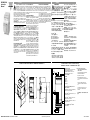
n WIRING DIAGRAM / SCHALTBILD / SCHÉMA DE CÂBLAGE /
DIAGRAMA DE CONEXIONES / COLLEGAMENTI ELETTRICI / 接线
A: 28 VDC supply IN
Eingang Spannungsversorgung 28 VDC
Entrée (IN) alimentation 28 Vcc
Entrada de alimentación de 28 VCC
Alimentazione ingresso 28 V CC
28 VDC 电源输入
B: HS Bus
HS-Bus
Bus GV
BUS SH
BUS SH
HS 总线
C: Dupline® Bus and 28 VDC power for
3-wire modules
Dupline®-Bus und Versorgungsspannung
28 VDC für 3-Leiter-Module
Bus Dupline® et alimentation 28 Vcc pour
modules sur 3-fils
Bus Dupline® y alimentación de 28 VCC
para módulos de 3 cables
Bus Dupline® e alimentazione da 28 V CC
per moduli a 3 fili
用于 3 线模块的 Dupline® 总线和
28 VDC 电源
Leggere attentamente il manuale
di istruzioni. Qualora l’apparecchio
venisse usato in un modo non spe-
cificato dal costruttore, la protezio-
ne prevista dall’apparecchio potreb-
be essere compromessa. Manutenzione:
Assicurarsi che il montaggio dei moduli estrai-
bili e le connessioni previste siano eseguiti cor-
rettamente al fine di evitare qualsiasi malfunzio-
namento o danneggiamento dello strumento.
Per mantenere pulito lo strumento usare un
panno inumidito; non usare abrasivi o solventi.
E’ necessario scollegare lo strumento prima di
eseguire la pulizia.
ATTENZIONE: unire o separare i vari moduli
SOLO quando questi NON sono alimentati.
SPECIFICHE DI ALIMENTAZIONE
Tensione di alimentazione 28 VCC (±20%),
2,6A (con massimo carico), CL.2. Tensione
d’impulso stimata 500 V (1,2/50µs) (IEC 60664-
1, tab. F.1). Assorbimento 3 W. Protezione da
inversione di polarità sì. Connessione A1 (+)
e A2 (-). Ritardo all’accensione tipico 4 s. Ri-
tardo di spegnimento 1 s. Tensione di uscita
Uscita di potenza, Nominale: 28 V c.c. ± 20%.
Nota: Nessuna separazione galvanica tra l’ali-
mentazione A1 + A2 e l’uscita di potenza. Utiliz-
zare sempre alimentazioni separate per ciascun
MCG SBP2MCG324.
n SPECIFICHE DEL DUPLINE®
Tensione nominale Dupline® 8,2 V. Tensione
massima Dupline® 10 V. Tensione di picco
min. Dupline® 4,5 V. Corrente massima
Dupline® 130 mA. Corrente massima su POW
2,6 A. Morsetto D+, D- e pow out. Nota: il
bus Dupline® è posto sul connettore superiore
e anche sul connettore del bus locale, sul lato
destro del modulo.
ITALIANO
n SPECIFICHE BUS HS
Tipo bus Bus ad alta velocità RS485. Protocollo
Protocollo proprietario interno. Connessione
Con bus locale (connettore sinistro e destro)
o morsetti GND, A(-), B(+). T1, T2: ingressi di
terminalizzazione. Devono essere messi in corto
sull’ultimo modulo della rete. Vedere gli schemi
di cablaggio.
n SPECIFICHE GENERALI
LED verde Stato di alimentazione: Acceso: Ali-
mentazione. Spento: alimentazione disattivata.
LED giallo Bus Dupline®: Acceso: il bus Dupli-
ne® funziona correttamente. Lampeggiante: c’è
un guasto sul bus Dupline®. Spento: il bus Du-
pline® è spento o non collegato. Bus: Spento:
nessuna comunicazione è presente sul bus HS.
Lampeggiante: errore di comunicazione sul bus
HS. Acceso: comunicazione OK sul bus HS.
Ambiente: Temp. di funzionamento: da -20 a
+50°C, Temp. di immagazzinaggio: da -50 a
+85°C. Umidità (non condensante) 20 - 80%
Umidità relativa. Grado di protezione Anteriore:
IP50, Terminale a vite: IP20. Grado di inquina-
mento: 2 (IEC 60664-1, par. 4.6.2). Rigidità
dielettrica Alimentazione di Dupline® e Dupline®
in uscita, 500 VCA per 1 minuto, 500 V impul-
so 1.2/50 μs (IEC60664-1, OVC II). Materiale
custodia Noryl. Dimensioni (HxLxP) 35 x 90
x 63.5 mm (Modulo 2-DIN). Peso 150 g. EMC
Immunità generale: EN61000-6-2, Emissione:
EN61000-6-3. Condizioni in caso di guasto
Se cessa la comunicazione tra SBP2MCG324 e
SBP2WEB24, l’uscita Dupline® verrà disattivata.
In questa circostanza tutti i moduli connessi al
bus entreranno in stato di uscita a prova di gua-
sto. Connessione Morsetto 12 a vite. Sezione
trasversale del cavo Massimo 1,5 mm2. Coppia
torcente 0,4 Nm / 0,8 Nm. Omologazioni CE,
cULus. Note UL Questo prodotto deve essere
alimentato da un adattatore CA nell’elenco delle
apparecchiature per le tecnologie dell’informa-
zione. Massima temperatura ambiente: 50 °C
D: These two terminals must be
short-circuited in the last module
of the network
Diese beiden Anschlüsse müssen am
letzten Modul im Netzwerk
kurzgeschlossen werden
Mettre impérativement ces bornes
en court-circuit sur le dernier module du
réseau.
Estos dos terminales deben corto
circuitarse en el último módulo de la
red
Questi due morsetti devono essere
messi in corto sull’ultimo modulo
della rete
在网络的最后一个模块中这两个端子必须
短接
35.0
5.0
44.0
45.0
14.5
90.0
90.0
35.0 44.0 14.5
45.0
5.0
n DIMENSIONS / ABMESSUNGEN / DIMENSIONS / DIMENSIONES / DIMENSIONI / 尺寸
n MODALITÀ DI FUNZIONAMENTO
Il generatore master Carpark SBP2MCG324 è
parte del sistema Carpark Dupline® e viene sem-
pre usato con il controller Carpark SBP2WEB24.
L’unità genera il segnale portante Dupline® a 3
fili con alimentazione e comunicazione per un
massimo di 90 sensori Carpark.
Fino a 7 SBP2MCG324 possono essere collega-
ti a un SBP2WEB24 localmente o tramite il con-
nettore laterale o RS485 per le lunghe distanze.
Le informazioni relative all’installazione, alla pro-
grammazione e all’uso di SBP2MCG324 si pos-
sono consultare nel manuale per lo strumento
di configurazione di SBP2WEB24 oppure nel
manuale d’installazione disponibile sul sito web:
HTTP://productselection.net
-
 1
1
-
 2
2


CARLO GAVAZZI SBP2MCG324 Bedienungsanleitung
- Typ
- Bedienungsanleitung
Verwandte Artikel
-
CARLO GAVAZZI SH2D10V424 Bedienungsanleitung
-
-
CARLO GAVAZZI CPTDINAV51HS2BX Installationsanleitung
-
-
-
-
-
-
-